Apparatus And Methods For Use In Establishing And/or Maintaining Controlled Flow Of Hydrocarbons During Subsea Operations
Beynet; Pierre Albert ; et al.
U.S. patent application number 13/457062 was filed with the patent office on 2012-12-27 for apparatus and methods for use in establishing and/or maintaining controlled flow of hydrocarbons during subsea operations. This patent application is currently assigned to BP CORPORATION NORTH AMERICA INC.. Invention is credited to Pierre Albert Beynet, Douglas Paul Blalock, Kevin James Devers.
| Application Number | 20120325489 13/457062 |
| Document ID | / |
| Family ID | 46026982 |
| Filed Date | 2012-12-27 |

| United States Patent Application | 20120325489 |
| Kind Code | A1 |
| Beynet; Pierre Albert ; et al. | December 27, 2012 |
APPARATUS AND METHODS FOR USE IN ESTABLISHING AND/OR MAINTAINING CONTROLLED FLOW OF HYDROCARBONS DURING SUBSEA OPERATIONS
Abstract
Apparatus includes a seal head having first and second ends and a sidewall having an internal diameter. The first end of the seal head is open to the environment, and the second end is closed to the environment by an end cap. The seal head includes an aperture configured to accommodate a subsea source. A tubular seal head extension is fluidly connected to the seal head end cap. The seal head extension has an external diameter, an external surface, and a length. A movable element having first and second ends and a sidewall structure having an internal diameter sufficiently larger than the external diameter of the extension forms an annulus between the movable element and the extension. The movable element first end opens to the environment, while its second end is closed by an end cap defining an exit fluidly connectable to a subsea collection system.
| Inventors: | Beynet; Pierre Albert; (Houston, TX) ; Blalock; Douglas Paul; (Katy, TX) ; Devers; Kevin James; (Katy, TX) |
| Assignee: | BP CORPORATION NORTH AMERICA
INC. Houston TX |
| Family ID: | 46026982 |
| Appl. No.: | 13/457062 |
| Filed: | April 26, 2012 |
Related U.S. Patent Documents
| Application Number | Filing Date | Patent Number | ||
|---|---|---|---|---|
| 61479769 | Apr 27, 2011 | |||
| Current U.S. Class: | 166/353 ; 166/367; 166/368 |
| Current CPC Class: | E21B 43/0122 20130101; E21B 37/06 20130101 |
| Class at Publication: | 166/353 ; 166/368; 166/367 |
| International Class: | E21B 43/013 20060101 E21B043/013; E21B 17/01 20060101 E21B017/01; E21B 33/038 20060101 E21B033/038 |
Claims
1. An apparatus comprising: a seal head comprising first and second ends and a seal head sidewall structure having an internal diameter, the sidewall structure connecting the first and second ends, the seal head first end open to the environment, the seal head second end closed to the environment by an end cap, the seal head further comprising at least one aperture configured to accommodate a subsea source of hydrocarbons; a tubular seal head extension fluidly connected to the end cap of the seal head, the tubular seal head extension having an internal diameter less than the internal diameter of the seal head, an external diameter, an external surface, and a length; and a movable element comprising first and second ends and a sidewall structure having an internal diameter sufficiently larger than the external diameter of the tubular seal head extension to form an annulus there between, the movable element sidewall structure connecting the movable element first and second ends, the movable element first end open to the environment, and the movable element second end closed to the environment by a movable element end cap defining an exit fluidly connectable to a subsea collection system.
2. The apparatus of claim 1 wherein the movable element comprises a first end opening configured to slidingly engage the external surface of the tubular seal head extension along its length.
3. The apparatus of claim 1 wherein the seal head comprises a second tubular member.
4. The apparatus of claim 3 wherein the movable element comprises a third tubular member.
5. The apparatus of claim 1 wherein the at least one aperture is in a seal head sidewall structure and is selected from curve-shaped apertures and non-curve-shaped apertures.
6. The apparatus of claim 5 wherein the curve-shaped apertures are selected from U-shaped apertures, parabolic apertures, and circular apertures.
7. The apparatus of claim 5 wherein the non-curve-shaped apertures are selected from square apertures, triangular apertures, and trapezoidal apertures.
8. The apparatus of claim 5 wherein the at least one apertures comprise one or more flexible sealing members.
9. The apparatus of claim 2 wherein the external surface of the tubular seal head extension is polished.
10. The apparatus of claim 9 wherein the opening of the movable element first end comprises a polished internal surface configured to engage the polished external surface of the tubular seal head extension.
11. The apparatus of claim 4 wherein the third tubular is connectable to a drill string.
12. The apparatus of claim 2 wherein the movable element first end further comprises a second opening configured to allow material to escape.
13. The apparatus of claim 1 further comprising one or more ROV handles attached to the seal head.
14. The apparatus of claim 1 further comprising one or more ROV handles attached to the movable element.
15. The apparatus of claim 1 wherein the seal head further comprises one or more access points for a functional fluid.
16. The apparatus of claim 1 wherein the movable element further comprises one or more access points for a functional fluid.
17. An apparatus comprising: a first tubular comprising first and second ends and a first tubular sidewall structure having an internal diameter, the sidewall structure connecting the first and second ends, the first end of the first tubular open to the environment, the first tubular second end closed to the environment by an end cap, the first tubular comprising at least one aperture in the first tubular sidewall structure configured to accommodate a subsea source of hydrocarbons; a second tubular fluidly connected to the end cap of the first tubular, the second tubular having an internal [diameter less than the internal diameter of the first tubular, an external diameter, an external surface, and a length; and a third tubular comprising first and second ends and a sidewall structure having an internal diameter sufficiently larger than the external diameter of the second tubular to form an annulus there between, the third tubular sidewall structure connecting the third tubular first and second ends, the third tubular first end open to the environment, and the third tubular second end closed to the environment by a third tubular end cap defining an exit fluidly connectable to a subsea collection system.
18. A method comprising: deploying a fluid collection apparatus from a surface vessel subsea near a subsea source of hydrocarbons, the apparatus comprising: a seal head comprising first and second ends and a seal head sidewall structure having an internal diameter, the sidewall structure connecting the first and second ends, the seal head first end open to the environment, the seal head second end closed to the environment by an end cap, the seal head comprising at least one aperture configured to accommodate a subsea source; a tubular seal head extension fluidly connected to the end cap of the seal head, the tubular seal head extension having an internal diameter less than the internal diameter of the seal head, an external diameter, an external surface, and a length; and a movable element comprising first and second ends and a sidewall structure having an internal diameter sufficiently larger than the external diameter of the tubular seal head extension to form an annulus there between, the movable element sidewall structure connecting the movable element first and second ends, the movable element first end open to the environment, and the movable element second end closed to the environment by a movable element end cap defining an exit fluidly connected to the vessel by a subsea collection system; positioning the apparatus to collect hydrocarbons from the source of hydrocarbons; and collecting hydrocarbons using the apparatus and the subsea collection system.
19. A method comprising: deploying a subsea collection system and a fluid collection apparatus from a surface vessel subsea near a subsea source of hydrocarbons, the apparatus comprising: a seal head comprising first and second ends and a seal head sidewall structure having an internal diameter, the sidewall structure connecting the first and second ends, the seal head first end open to the environment, the seal head second end closed to the environment by an end cap, the seal head comprising at least one aperture configured to accommodate a subsea source of hydrocarbons; a tubular seal head extension fluidly connected to the end cap of the seal head, the tubular seal head extension having an internal diameter less than the internal diameter of the seal head, an external diameter, an external surface, and a length; and a movable element comprising first and second ends and a sidewall structure having an internal diameter sufficiently larger than the external diameter of the tubular seal head extension to form an annulus there between, the movable element sidewall structure connecting the movable element first and second ends, the movable element first end open to the environment, and the movable element second end closed to the environment by a movable element end cap defining an exit fluidly connected to the vessel by the subsea collection system; positioning the apparatus to collect hydrocarbons from the source of hydrocarbons; displacing seawater from the subsea collection system and the fluid collection apparatus by forcing a low-density gas down the subsea collection system at least during the positioning of the apparatus until the gas bubbles out of a first end of the fluid collection apparatus, limiting ingress of seawater or hydrocarbon gas hydrates into the subsea collection system and apparatus thus limiting plugging of the subsea collection system and apparatus; moving the surface vessel so that the apparatus is a few meters above the subsea source, with the apparatus in the hydrocarbon plume; landing the seal head of the fluid collection apparatus on the subsea source, while the apparatus remains filled with low-density gas; gradually reducing flow of the gas and gradually opening a choke to establish and maintain flow of collected hydrocarbons up the apparatus and subsea collection system.
20. The method of claim 19 further comprising pumping a functional fluid into the apparatus through one or more valves on the apparatus during at least the collecting step, limiting hydrocarbon gas hydrate formation during the collecting of hydrocarbons.
21. The method of claim 19 further comprising monitoring flow into and out of the first end of the movable element.
22. The method of claim 19 further comprising allowing the movable element and attached subsea collection system to move up and down with heave of the surface vessel.
23. The method of claim 19 further comprising guiding positioning of the apparatus using one or more ROVs.
Description
CROSS-REFERENCE TO RELATED APPLICATIONS
[0001] This application is related to and claims priority under 35 U.S.C. .sctn.119(e) to assignee's U.S. provisional patent application Ser. No. 61/479,769, filed Apr. 27, 2011, incorporated herein by reference.
BACKGROUND INFORMATION
[0002] 1. Technical Field
[0003] The present disclosure relates in general to tools (apparatus) and methods useful in the subsea marine hydrocarbon exploration, production, well drilling, well completion, well intervention, and containment and disposal fields.
[0004] 2. Background Art
[0005] Assignee's U.S. provisional patent application Ser. No. 61/479,769, filed Apr. 27, 2011, describes broadly methods of using nitrogen or other low-density fluid to establish and/or maintain hydrocarbon flow in a riser from a subsea source to one or more surface vessels during subsea marine operations such as hydrocarbon containment and disposal operations, hydrocarbon exploration, production, well drilling, well completion, and well intervention.
SUMMARY
[0006] Apparatus of the present disclosure may be used to establish and/or maintain hydrocarbon flow in a riser extending from one or more subsea sources to one or more surface vessels.
[0007] A first aspect of the disclosure is an apparatus comprising: [0008] a seal head comprising first and second ends and a seal head sidewall structure having an internal diameter, the sidewall structure connecting the first and second ends, the seal head first end open to the environment, the seal head second end closed to the environment by an end cap, the seal head comprising at least one aperture configured to accommodate a subsea source; [0009] a tubular seal head extension fluidly connected to the end cap of the seal head, the tubular seal head extension having an internal diameter less than the internal diameter of the seal head, an external diameter, an external surface, and a length; and [0010] a movable element comprising first and second ends and a sidewall structure having an internal diameter sufficiently larger than the external diameter of the tubular seal head extension to form an annulus there between, the movable element sidewall structure connecting the movable element first and second ends, the movable element first end open to the environment, and the movable element second end closed to the environment by a movable element end cap defining an exit fluidly connectable to a subsea collection system.
[0011] In certain embodiments, the seal head, tubular seal head extension, and movable element may each comprise a tubular member. In other embodiments the movable element may have a diameter sufficiently large to serve as a gas/liquid separator, and in certain embodiments as a gas/first liquid/second liquid and solids separator. In certain embodiments the apparatus may comprise more than one seal head fluidly connected to the movable element.
[0012] A second aspect of the disclosure are methods of using an apparatus of this disclosure, comprising:
[0013] deploying a fluid collection apparatus from a surface vessel subsea near a subsea source of hydrocarbons, the apparatus comprising: [0014] a seal head comprising first and second ends and a seal head sidewall structure having an internal diameter, the sidewall structure connecting the first and second ends, the seal head first end open to the environment, the seal head second end closed to the environment by an end cap, the seal head comprising at least one aperture configured to accommodate a subsea source; [0015] a tubular seal head extension fluidly connected to the end cap of the seal head, the tubular seal head extension having an internal diameter less than the internal diameter of the seal head, an external diameter, an external surface, and a length; and [0016] a movable element comprising first and second ends and a sidewall structure having an internal diameter sufficiently larger than the external diameter of the tubular seal head extension to form an annulus there between, the movable element sidewall structure connecting the movable element first and second ends, the movable element first end open to the environment, and the movable element second end closed to the environment by a movable element end cap defining an exit fluidly connected to the vessel by a subsea collection system; positioning the apparatus to collect hydrocarbons from the source of hydrocarbons; and [0017] collecting hydrocarbons using the apparatus and subsea collection system.
[0018] Certain method embodiments may comprise: [0019] displacing seawater from the subsea collection system and apparatus by forcing a low-density gas down the subsea collection system at least during the positioning of the apparatus until the gas bubbles out of the first end of the seal head, limiting ingress of seawater or hydrocarbon gas hydrates into the subsea collection system and apparatus thus limiting plugging of the subsea collection system and apparatus; [0020] moving the surface vessel so that the apparatus is a few meters above the subsea source, with the apparatus in the hydrocarbon plume; [0021] landing the seal head of the fluid collection apparatus on the subsea source, while the apparatus remains filled with low-density gas; and [0022] gradually reducing flow of the gas and gradually opening a choke to establish and maintain flow of collected hydrocarbons through the apparatus and subsea collection system.
[0023] These and other features of apparatus and methods of the disclosure will become more apparent upon review of the brief description of the drawings, the detailed description, and the claims that follow.
BRIEF DESCRIPTION OF THE DRAWINGS
[0024] The manner in which the objectives of this disclosure and other desirable characteristics may be obtained is explained in the following description and attached drawings in which:
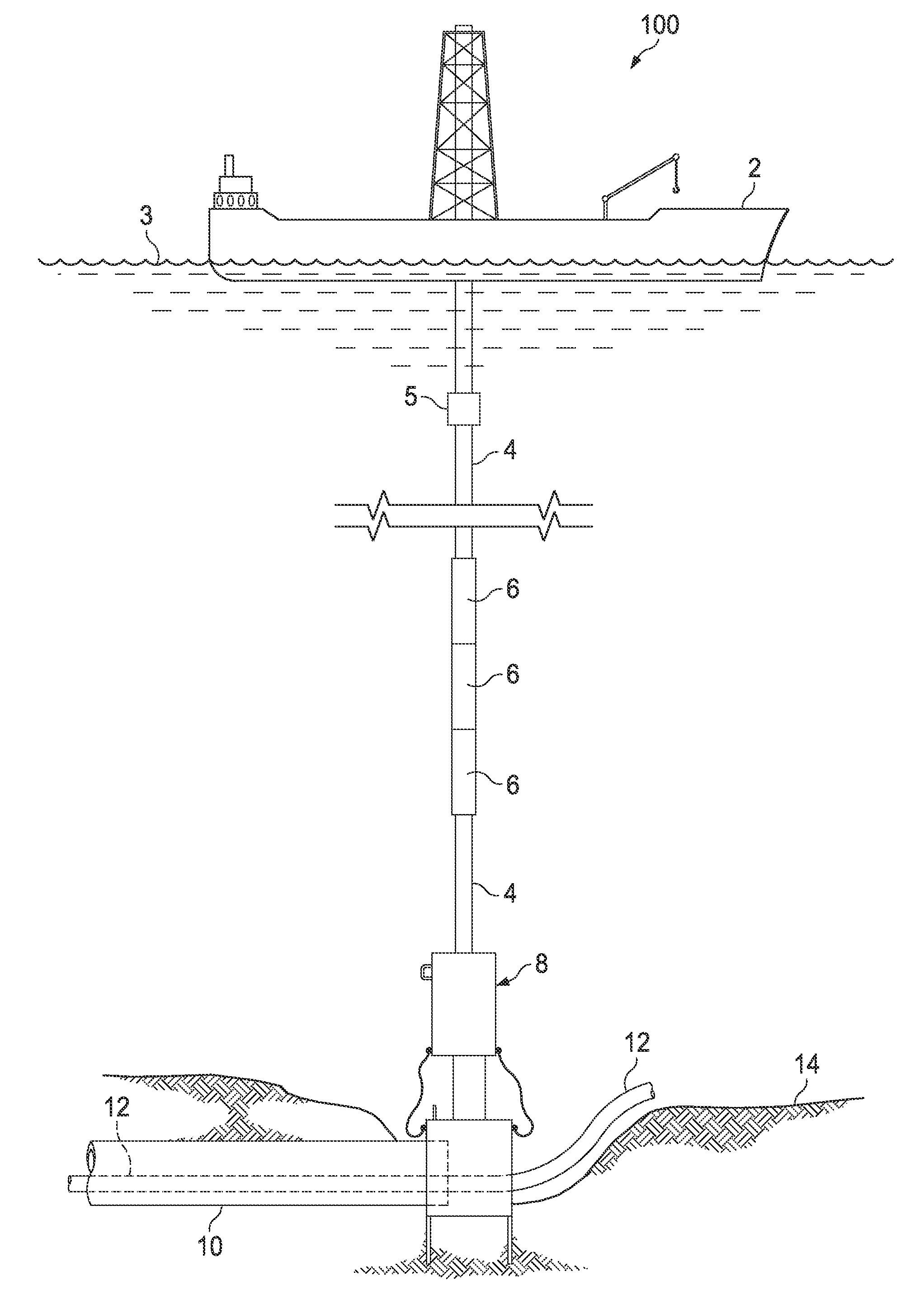
[0025] FIG. 1 is a schematic side view of a subsea collection system employing an apparatus and method in accordance with the present disclosure;
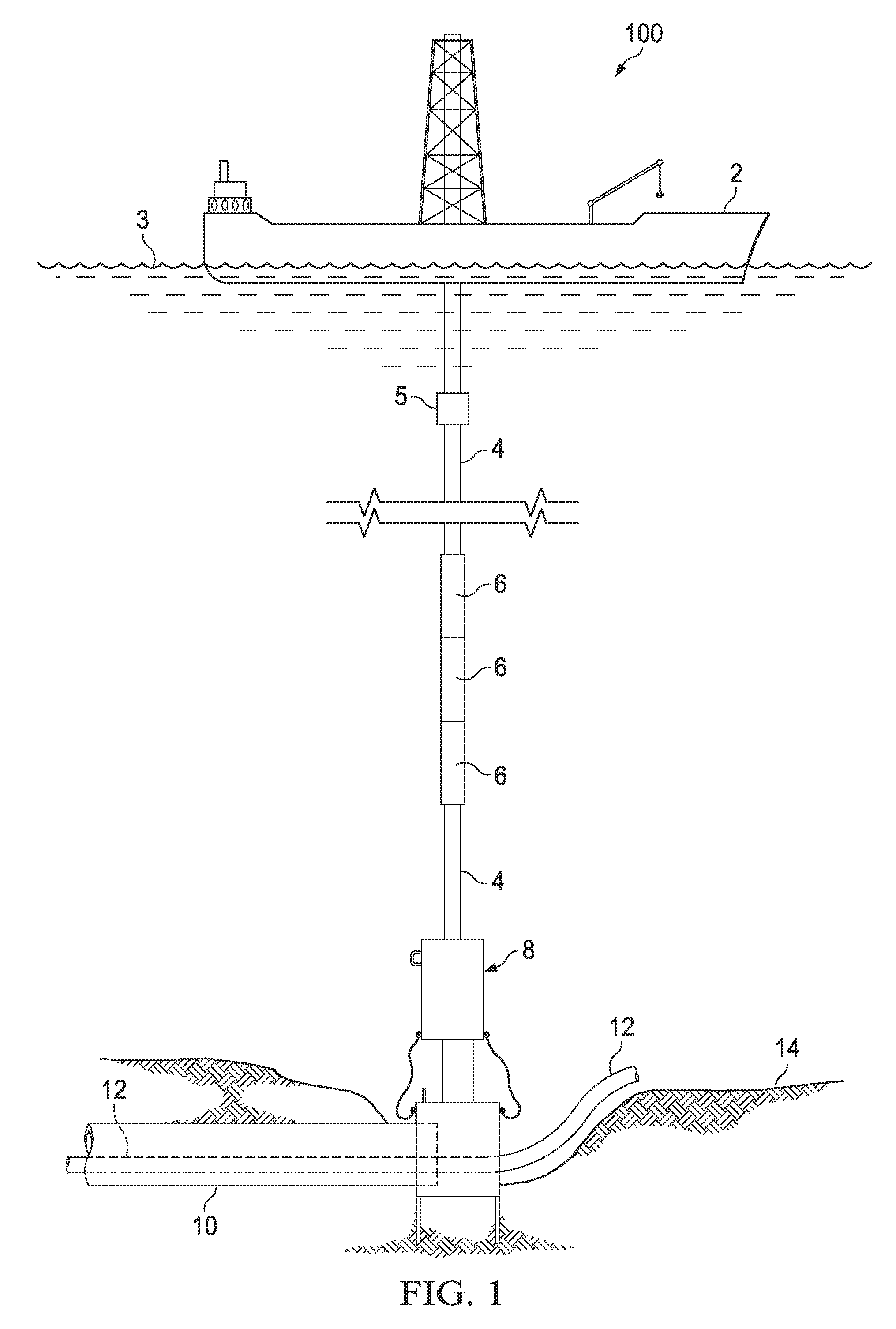
[0026] FIG. 2 is a more detailed schematic cross-sectional view of the apparatus illustrated in FIG. 1;
[0027] FIGS. 3, 4, and 5 are detailed schematic perspective views, with portions cut away, of three apparatus embodiments in accordance with the present disclosure;
[0028] FIGS. 6 and 7 are schematic side elevation views of two other seal head embodiments, with FIG. 7A illustrating a schematic plan view of the embodiment illustrated in FIG. 7; and
[0029] FIGS. 8 and 9 are logic diagrams of two method embodiments in accordance with the present disclosure.
[0030] It is to be noted, however, that the appended drawings are not necessarily to scale and illustrate only typical embodiments of this disclosure, and are therefore not to be considered limiting of its scope, for the disclosure may admit to other equally effective embodiments.
DETAILED DESCRIPTION
[0031] In the following description, numerous details are set forth to provide an understanding of the disclosed methods. However, it will be understood by those skilled in the art that the methods covered by the claims may be practiced without these details and that numerous variations or modifications from the specifically described embodiments may be possible and are deemed within the claims. All U.S. published patent applications and U.S. patents referenced herein are hereby explicitly incorporated herein by reference. In the event definitions of terms in the referenced patents and applications conflict with how those terms are defined in the present application, the definitions for those terms that are provided in the present application shall be deemed controlling.
[0032] Apparatus and methods of this disclosure may be employed for deepwater subsea containment, disposal, production, and well intervention. While many of the methods described herein may be used in the context of containment and disposal, it is explicitly noted that the methods described herein are not restricted to containment and disposal operations, but may be used in conjunction with any "subsea source", as that term is defined herein. As used herein, the term "collection system" includes any facility, component, assembly, and the like, such as a subsea riser and fluid transfer system that may fluidly connect an apparatus of the present disclosure to a surface vessel. As used herein the term "upstream" when used to describe deployment of a collection system, riser and/or collection tool means the collection system, riser and/or collection tool is/are not in the plume of hydrocarbons emanating from a subsea source. As used herein the term "hydrocarbon gas hydrates" means hydrates formed from hydrocarbon gases selected from the group consisting of methane, ethane, propane, butane, isobutane, isobutene and mixtures thereof. The methods of the present disclosure may be fully or partially implemented before, during, and after a collection system and apparatus of the present disclosure are deployed to collect hydrocarbons from a subsea component that has been compromised (for example, but not limited to, a subsea well blowout, damaged subsea blow out preventer (BOP), damaged subsea riser or other subsea conduit, damaged subsea manifold, and the like), and/or other subsea source(s), such as seeps from the seafloor, and may be used in any marine environment, but are particularly useful in deep and ultra-deep subsea marine environments. The methods may also be used to control and/or totally prevent hydrocarbon gas hydrate formation during deployment of a subsea riser prior to and during a subsea operation to collect hydrocarbons producing naturally. Methods of the disclosure may also be used to start the flow or enhance the flow rate of source fluids using gas lift principles by injecting nitrogen or other gas, with or without produced gas, near the lower end of the riser.
[0033] In the containment and disposal context, in certain embodiments the methods described herein may be used in subsea marine environments to establish and/or maintain flow of material (hydrocarbons, or fluids comprising hydrocarbons) in a riser from a subsea source to one or more surface vessels. As used herein, the phrases "maintain flow" and "maintaining flow" mean controlling and/or totally preventing hydrocarbon gas hydrate formation during deployment of a subsea collection system and apparatus. The terms "establishing flow" and "maintaining flow" may also comprise using gas lift or subsea pumping methods. Both the establishment and maintenance of flow may involve preventing, managing, mitigating, and/or controlling hydrocarbon gas hydrate formation directly in the collection system and apparatus hydrocarbon flow passage prior to, during deployment, and during use of the collection system and apparatus, and any subsea equipment, accessory components, and the like attached to the collection system and apparatus for containment and disposal operations, as well as other operations. The methods and apparatus of this disclosure may not only be used for containment and disposal operations, but may also be used for exploration, production, drilling, completion, and intervention. In certain embodiments, a chamber filled with low-density fluid may be formed in the collection tool, allowing the establishing of a shielded flow of hydrocarbons from the source of hydrocarbons. By "shielded flow" is meant that the flow of hydrocarbons is shielded from substantial contact with seawater. Since water is a necessary ingredient in formation of hydrocarbon gas hydrates, this advantageously mitigates their formation.
[0034] Certain apparatus of the present disclosure, which may be referred to alternatively herein as "collection tools", "fluid collection tools", "fluid collection apparatus", or simply "tools", may comprise a seal head comprising first and second ends and a seal head sidewall structure having an internal diameter, the sidewall structure connecting the first and second ends. The seal head first end may be open to the environment, and the seal head second end may be closed to the environment by an end cap, the seal head comprising at least one aperture in the sidewall structure or first end configured to accommodate a subsea source, for example a damaged subsea riser or pipeline, or a subsea seep.
[0035] Certain apparatus may comprise a tubular seal head extension fluidly connected to the end cap of the seal head, the tubular seal head extension having an internal diameter less than the internal diameter of the seal head, an external diameter, an external surface, and a length.
[0036] Certain apparatus may comprise a movable element comprising first and second ends and a sidewall structure having an internal diameter sufficiently larger than the external diameter of the tubular seal head extension to form an annulus there between. In certain embodiments the movable element sidewall structure may connect the movable element first and second ends, the movable element first end open to the environment, and the movable element second end closed to the environment by a movable element end cap defining an exit fluidly connectable to a subsea collection system.
[0037] In certain apparatus embodiments the movable element may comprise a first end opening configured to slidingly engage the external surface of the tubular seal head extension along its length.
[0038] In certain apparatus embodiments the seal head may comprise a second tubular member, and the movable element may comprise a third tubular member.
[0039] In certain apparatus embodiments the at least one aperture in the seal head sidewall structure may be selected from curve-shaped apertures and non-curve-shaped apertures. Curve-shaped apertures may be selected from U-shaped apertures, parabolic apertures, circular apertures, and the like. Non-curve-shaped apertures may be selected from square apertures, triangular apertures, trapezoidal apertures, and the like.
[0040] In certain apparatus embodiments the at least one aperture may comprise one or more flexible sealing members generally adjacent the edges of the aperture, for example, but not limited to, rubber sealing members.
[0041] In certain apparatus embodiments the external surface of the tubular seal head extension may be polished. In certain apparatus embodiments the opening of the movable element first end may comprise a polished internal surface configured to engage the polished external surface of the tubular seal head extension.
[0042] In certain apparatus embodiments wherein the movable member is a third tubular, the third tubular may be connectable to a drill string.
[0043] In certain apparatus embodiments the movable element first end may comprise a second opening configured to allow material to escape, such as a small amount of hydrates, viewable subsea for example by a diver or a remotely operable vehicle (ROV). Certain apparatus embodiments may comprise one or more ROV handles attached to the seal head. Certain apparatus embodiments may comprise one or more ROV handles attached to the movable element.
[0044] In certain apparatus embodiments the seal head may comprise one or more access points for a functional fluid. In certain apparatus embodiments the movable element may comprise one or more access points for a functional fluid.
[0045] Certain method embodiments may comprise deploying a fluid collection apparatus of the present disclosure from a surface vessel subsea near a subsea source of hydrocarbons, positioning the apparatus to collect hydrocarbons from the source of hydrocarbons, and collecting hydrocarbons using the apparatus and subsea collection system.
[0046] Certain method embodiments may comprise displacing seawater from the subsea collection system and apparatus by forcing a low-density gas into the subsea collection system at least during the positioning of the apparatus until the gas bubbles out of the first end of the seal head, limiting ingress of seawater or hydrocarbon gas hydrates into the subsea collection system and apparatus thus limiting plugging of the subsea collection system and apparatus. Certain methods may comprise moving the surface vessel so that the apparatus is a few meters above the subsea source, with the apparatus in the hydrocarbon plume. Certain methods may comprise landing the seal head on the subsea source, while the apparatus remains filled with low-density gas, and gradually reducing flow of the gas and gradually opening a choke to establish and maintain flow of collected hydrocarbons up the apparatus and subsea collection system.
[0047] Certain method embodiments may comprise pumping a functional fluid into the apparatus through one or more valves or other access points on the apparatus during at least the collecting step, limiting hydrocarbon gas hydrate formation during the collecting of hydrocarbons.
[0048] Certain method embodiments may comprise monitoring flow into and/or out of the first end of the movable element.
[0049] Certain method embodiments may comprise allowing the movable element and attached subsea collection system to move up and down with heave of the surface vessel.
[0050] Certain method embodiments may comprise guiding positioning of the apparatus using one or more ROVs.
[0051] Certain method embodiments may comprise connecting riser sections at or near the sea surface on one or more surface vessels. Certain embodiments may comprise constructing the riser using high strength steel tubulars using threaded coupled connectors. In certain embodiments the tubulars and the threaded coupled connectors may be insulated. In certain embodiments the insulated tubulars may be vacuum-insulated tubulars. In certain embodiments the riser may be constructed of one or more tubulars selected from the group consisting of drill pipe, reel pipe, flexible pipe, composite pipe, and hose.
[0052] Certain method embodiments may comprise controlling hydrocarbon gas hydrate formation by limiting contact of liquids or solids with inner surfaces of the collection system and tool during at least the positioning of the tool subsea. In certain embodiments a functional fluid may be pumped into the tool, the functional fluid selected from the group consisting of wax inhibitor, asphaltene inhibitor, hydrocarbon gas hydrate inhibitor, and combinations thereof. In certain embodiments, a dispersant chemical may be introduced into any hydrocarbons mixing with seawater. Methods of this disclosure where one or more functional fluids are used in the tool in conjunction with a low-density fluid being forced down the collection system, and optionally a dispersant chemical, are deemed methods of limiting formation of hydrocarbon gas hydrates, whereas methods of using only a low-density fluid forced down the collection system (and tool, if present during deployment) and optionally a dispersant, are deemed methods of controlling hydrocarbon gas hydrate formation. In the latter methods, the risk of hydrate formation is higher, but the form of the hydrate may be controlled to a manageable level by preventing flakes of hydrates forming drifts, or hard compactions of hydrocarbon gas hydrates.
[0053] As used herein the phrase "on the seabed", when used to describe location of a tool or other item, is understood to include tools in baskets, or on platforms or manifolds, that are in turn resting directly on (touching) the seabed. As used herein "ceasing the forcing of low-density fluid" means the forcing of the low-density fluid down the collection system, riser, or other facility, is gradually reduced and then stopped during the collection step.
[0054] In certain method embodiments the collection tool may be designed to be positioned over a leaking riser or other subsea hydrocarbon source. In certain embodiments, tools of the present disclosure may comprise a large diameter lower conduit, for example a 32 inch (81 cm) diameter pipe, which has U-cuts or equivalent to accommodate a riser or pipeline laying on or above the seabed and a drill pipe (if present) also laying on or above the seabed. At its upper end the large diameter conduit may have a smaller diameter conduit (for example 10 inches (25 cm) diameter) attached thereto, which may function as a chimney. The smaller diameter conduit extends upward into (and may slidingly engage) another conduit, for example a pipe having diameter intermediate to the large and small diameter conduits. This tool and variations of it and their operation are further described herein.
[0055] In certain method embodiments the surface vessel may be a drill ship or vessel including a drilling rig, and the collection system may include a riser having an upper end connected to the drill ship or drilling rig. In certain embodiments the surface vessel may be a mobile offshore drilling unit (MODU). In certain embodiments the surface vessel may be a floating storage and/or off-loading vessel, such as a floating production, storage, and off-loading (FPSO) vessel. The surface vessel may be moored to a turret, or dynamically positioned, or both.
[0056] In certain embodiments the low-density fluid may be selected from the group consisting of nitrogen, nitrogen-enriched air, helium, chlorine, hydrogen, argon, krypton, neon, dehumidified versions of any of these, and/or any mixture thereof. In certain embodiments the low-density fluid may comprise a gas atmosphere consisting essentially of nitrogen, where the phrase "consisting essentially of nitrogen" means that the gas atmosphere is mostly nitrogen plus any allowable impurities that would not affect the ability of the nitrogen to limit hydrocarbon gas hydrate formation. The pressure of the low-density fluid in the riser near the distal end of the riser and in the tool attached to the riser should be such as to permit outward flow of the nitrogen (or other gas) during deployment and before start up.
[0057] In certain methods the connecting of the riser sections may comprise connecting drill pipe riser sections, or other riser sections, using threaded joints. In certain methods the connecting of riser sections may comprise connecting sections of insulated pipe using threaded or other joints; in certain embodiments the threaded joints may be vacuum insulated tubing with insulation covers for the threaded connections.
[0058] In certain methods, if flow up the riser or other collection system is not sufficient, certain methods may comprise providing an auxiliary method to achieve sufficient flow selected from the group consisting of pumping the hydrocarbon up the riser using a subsea pump, employing gas lift with a non-oxidizing mixture of collected gas (with or without added nitrogen) added through an umbilical or coiled tubing employing a compressor, and employing gas lift using a flue gas (with or without added nitrogen) added through an umbilical or coiled tubing employing a compressor.
[0059] In certain other embodiments the riser may further comprise one or more drill collars in the string, for example near the distal end of a drill pipe riser, in order to provide weight to the drill pipe riser during deployment.
[0060] As used herein the phrase "subsea source" includes, but is not limited to: 1) production sources such as subsea wellheads, subsea BOPs, other subsea risers, subsea manifolds, subsea piping and pipelines, subsea storage facilities, and the like, whether producing, transporting and/or storing gas, liquids, or combination thereof, including both organic and inorganic materials; 2) subsea containment sources of all types, including damaged subsea BOPs, risers, manifolds, tanks, and the like; and 3) fissures or openings in the sea floor.
[0061] Certain hydrate inhibition method embodiments include those wherein the hydrate-inhibitor liquid chemical is selected from the group consisting of alcohols (such as methanol, ethanol, and the like) and glycols (such as ethylene glycol, propylene glycol, and the like, and mixtures of glycols). An important property of propylene glycol is its ability to lower the freezing point of water. This results in its use in the formulation of antifreeze mixtures. Propylene glycol is almost as efficient as ethylene glycol in antifreeze applications. Solutions of inhibited propylene glycol (propylene glycol containing a corrosion inhibitor) may also be employed.
[0062] In certain method embodiments a hydrocarbon dispersant may be employed, for example pumped around the base of a seal head, or around the bottom of a movable element. One suitable dispersant may be the chemical known under the trade designation COREXIT.RTM., whose composition is given more fully herein.
[0063] Yet other method embodiments comprise, in the event of a hurricane or planned disconnect, disconnecting the collection system and movable element in a controlled manner using upward force, which force may have a lateral component. Even if not performed in a controlled manner, such as during an unplanned weather event, or ship malfunction event, apparatus of the present disclosure are designed such that the movable element may disconnect from the seal head extension and seal head without extensive damage to the seal head, seal head extension, movable element, and collection system. In the case of a surface vessel drive off the movable element is just dragged off by the drill pipe or other collection system. Optional nylon or other cables attached to the movable element and seal head may break, leaving the seal head and seal head extension on the seafloor. It is preferable to close the upper choke prior to disconnecting to prevent the sucking up of water in the riser. Once disconnected a low-density fluid may be pumped into the riser to mix with or displace the hydrocarbons and permit seawater to fill up the riser prior to retrieving it.
[0064] In certain method embodiments, if cooling at the surface or subsea choke is excessive during collection of the hydrocarbons, the hydrocarbon flow may be heated prior to the choke by pumping heated seawater into an annulus between the riser and an external riser, or heating the oil on the deck of the surface vessel.
[0065] The primary features of the methods of the present disclosure will now be described with reference to the drawing figures, after which some of the operational details will be further explained. In accordance with the present disclosure, FIG. 1 is a schematic side view of a subsea collection system 100 employing an apparatus 8 and method in accordance with the present disclosure. A surface vessel 2, for example an MODU on the sea surface 3, is illustrated as having a drill string 4 attached thereto. In certain embodiments, for example if surface vessel 2 is an FPSO, a fluid transfer system 5 may be provided, and one or more drill collars 6, which are essentially heavier, more robust sections of drill pipe. Drill pipe 4, or a drill collar 6 as the case may be, is fluidly connected to a collection tool 8 of the present disclosure, illustrated schematically as sealing around a damaged riser 10 having an internal drill pipe or service pipe 12 partially buried in mud on seafloor 14.
[0066] Examples of useful fluid transfer systems may be the fluid transfer systems described in assignee's co-pending U.S. provisional patent application serial number 61480368, filed Apr. 28, 2011, incorporated herein by reference, comprising a fluid connector assembly configured to connect a subsea system designed to route hydrocarbon fluids from a subsea source to a surface vessel and disconnect on command. The fluid connector assembly may comprise a hydraulic quick disconnect fluid connector comprising a first quick disconnect portion detachable from a second quick disconnect portion upon receipt of a disconnect command. The assembly may comprise a first hydraulically-operated isolation valve in the first quick disconnect portion, and a second hydraulically-operated isolation valve in the second quick disconnect portion, the isolation valves configured to close upon receipt of a close command, and a plurality of hydraulic fluid-conveying tubes, at least one tube connected to each of the valves and to the hydraulic quick disconnect fluid connector, and configured to execute the disconnect and close commands.
[0067] FIG. 2 is a more detailed schematic cross-sectional view of collection tool 8 illustrated in FIG. 1. Collection tool 8 includes, in this embodiment, a seal head 20, which in certain embodiments may be a large diameter conduit, and a tubular seal head extension 18, which in certain embodiments may be a small diameter conduit. A sliding seal 16, which in certain embodiments may be a conduit having a diameter intermediate that of seal head 20 and seal head extension 18, is also included in embodiment 8. In embodiment 8 seal head 20 includes apertures 22 and 24 accommodating damaged riser 10 and a drill pipe or service pipe 12, respectively. As more fully explained herein in reference to FIG. 4, a polished seal area 26 may be included. FIG. 2 schematically illustrates a formation of hydrates 28 on the inside of sliding seal 16 and external of tubular seal head extension 18, and a layer of liquid hydrocarbons 30. A small amount of escaping hydrates 32 may be allowed so as to confirm their formation and take remedial action, as further explained herein. A pair of nylon ropes or other cables 34 may be attached on stops variously positioned on seal head 20 and sliding seal 16 as illustrated. Cables 34 may be advantageous in case of surface vessel 2 drive-off or inclement weather, allowing sliding seal 16 to detach from the remainder of collection tool 8 in case sealing head 20 becomes snagged. During normal operation, hydrocarbons and other produced fluids travel through collection tool 8 as indicated by arrow 36 and drill pipe 4 or other collection system to surface vessel 2.
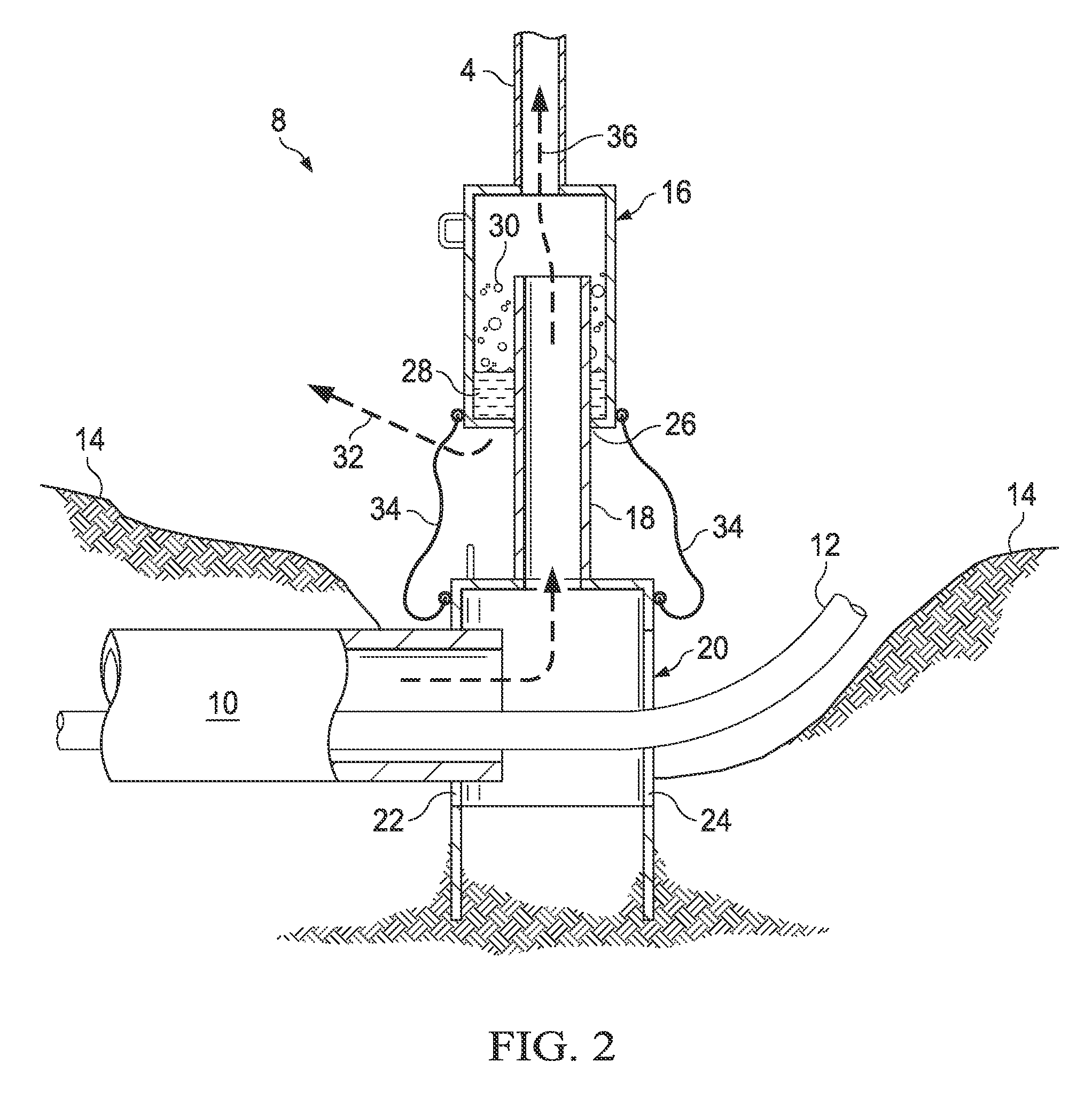
[0068] FIGS. 3 and 4 are detailed schematic perspective views, with portions cut away, of two collection tool embodiments 70 and 80 in accordance with the present disclosure. Embodiment 70 illustrated in FIG. 3 includes flexible sealing members 38 adjacent apertures 22 and 24. Flexible sealing members 38, which may be for example rubber or other flexible member, encourage sealing of seal head 20 about a subsea source, such as a damaged riser (not illustrated in FIG. 3). Also depicted schematically in FIG. 3 is a weld area 40 where seal head extension 18 is secured to a top flange or end 41 of seal head 20, and a weld area 42, where drill pipe 4 connects to a first end 44 of sliding seal 16. Rather than welding, weld areas 40 and 42 may be replaced by other fasteners known for use with subsea well heads, such as flanged connections, dog connectors, and the like. Seal head 20 includes a second end 43 that enters into mud on the seafloor. A sidewall structure 49 of seal head 20 connects first end 41 and second end 43, and a sidewall structure 17 of sliding seal 16 connects to first end 44. In embodiment 70, sliding seal member 16 does not include a bottom end, as may be seen in the cut-out section 45 of sliding seal member 16. Rather, the lengths and relative diameters of sliding seal member 16 and tubular seal head extension 18 are sufficient, along with the relative densities of hydrocarbons, seawater, and any hydrates formed, to prevent significant escape of hydrocarbons from sliding seal member 16 bottom area. Included in embodiment 70 are an optional ROV handle 46 on seal head 20 and an optional ROV handle 48 on sliding seal member 16, which, as those familiar with this art will recognize, may be placed on the collection tool 70 in many locations, and are merely examples. A double-headed arrow in FIG. 3 indicates the possible movement directions of sliding seal member 16 as the surface vessel heaves up and down.
[0069] In other embodiments, such as in embodiment 80 illustrated schematically in FIG. 4, a low pressure polished seal area 26 on the external surface of tubular seal head extension 18 may be provided which seals against a polished bore 19 in a bottom plate 47 of sliding seal member 16. In embodiment 80, the external surface of tubular seal head extension 18 may be polished at least along the length where it is expected to engage polished bore 19. One or more pilot holes 50 may be provided in bottom plate 47 to witness escape of any hydrates that may form, for example by a camera attached to an ROV. Pilot holes may be equipped with downward tubular extensions to substantially prevent water mixing with the collected fluid, such as illustrated at 501 in FIG. 5.
[0070] Optionally, embodiments 70 and 80, and other embodiments within the present disclosure, may include one or more access valves 52 and 54. Access valves may allow one or more functional fluids to be pumped into seal head 20 and/or sliding seal member 16, respectively, for example a hydrate inhibitor fluid.
[0071] In embodiments 70 and 80 of FIGS. 3 and 4 respectively, sliding seal member 16 may have a length ranging from about 5 ft. to about 150 ft. (about 1.5 m to about 46 m) or longer, or from about 5 ft. to about 75 ft. (from about 1.5 m to about 23 m), or from about 5 ft. to about 20 ft. (about 1.5 m to about 6 m), but in any case is long enough to overlap with a substantial portion of the length of seal head extension 18 so that a top open end 21 of tubular seal head extension 18 is within the cavity formed by sidewall structure 17 of seal head extension 18. Similarly, the ratio of external diameter of tubular seal head extension 18 and internal diameter of sidewall structure 17 of sliding seal member 16 should be small enough to allow movement between the two and form an annulus 60 between the two. Note that sizes (diameters) of seal head 20, tubular seal head extension 18, and sliding seal member 16 may be changed from those discussed above, with possible sacrifice in response time. Piping of 21-inch (53 cm) and 10-inch (25 cm) diameter may be available in 20-foot (6.1 m) sections, enough to provide the telescopic stroke of seal head extension 18 in sliding seal member 16.
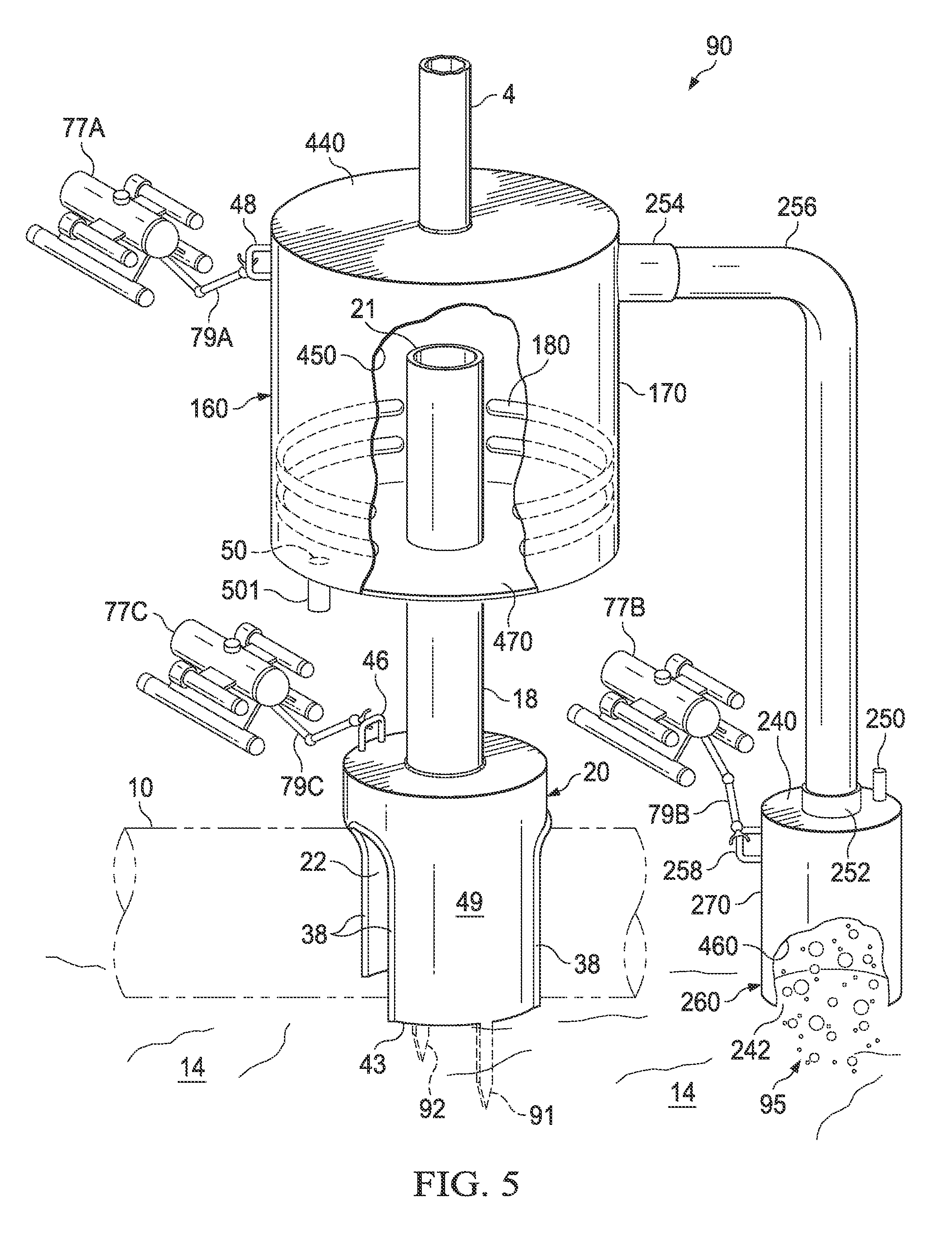
[0072] FIG. 5 is a schematic perspective view of another apparatus embodiment 90 with the present disclosure, illustrating additional features of various embodiments. Embodiment 90 is illustrated sealing around a damaged riser 10 laying on seafloor 14 (both damaged riser 10 and seafloor 14 illustrated in phantom). For example, embodiment 90 may include a larger diameter movable member 160 having a sidewall surface 170 connecting ends 440 and 470. Movable member 160 may have an internal diameter that is several times, or even several ten times or more than that of the external diameter of seal head extension 18, allowing movable member 160 to function as a separator, for example, a gas/liquid separator, or liquid/liquid separator, or gas/first liquid/second liquid separator, or gas/liquid/solid separator. As viewed through cut-out portion 450 of sidewall 170, movable member 160 may also include one or more optional internal baffles or separation enhancement members, 180, attached to the inside surface of movable member 160, for example by welding, riveting, and the like.
[0073] Another optional feature may be the provision of one or more stabilizing guide legs, such as guide legs 91 and 92 in FIG. 5 extending from near the bottom of seal head 20, and which penetrate into seafloor 14. One of guide legs 91, 92 may be longer than the other, as illustrated in FIG. 5, where guide leg 91 is longer than guide leg 92. This arrangement could allow pivoting of the apparatus about a first, longer guide leg before setting the second guide leg into the seafloor. Guide legs 91, 92 may be integral with or attached separately to seal head 20.
[0074] Certain embodiments may include more than one collection device connected to the same drill pipe 4, as illustrated in embodiment 90 of FIG. 5. Illustrated in FIG. 5 is a second seal head 260 having an aperture 242 in its bottom end, which is sunk into seafloor 14. As illustrated in cut-out portion 460 of sidewall 270, hydrocarbons and/or other material 95 seeping from the seafloor (naturally or due to a sub-seafloor leak) may be captured using this apparatus. Seal head 260 includes a top end 240 fluidly connected to movable member 160 through a subsea connector 252, a conduit 256, and another subsea connector 254 as illustrated. Optionally, seal head top end 240 may include one or more hot stab connections 250 to allow injection of a functional fluid, such as nitrogen or a hydrate inhibitor. A further option may be the provision of one or more access handles, 258, for example for access by an ROV 77B and one of its positioning arms 79B. Other ROVs, for example ROV 77A and 77C, may be used to guide positioning of movable member 160 and seal head 20, respectively. ROV 77A may have a mechanical positioning arm 79A that grasps handle 48, and ROV 77C may have a mechanical positioning arm 79C that grasps handle 46. ROVs of this nature are available from Oceaneering International, Inc. Houston, Tex.
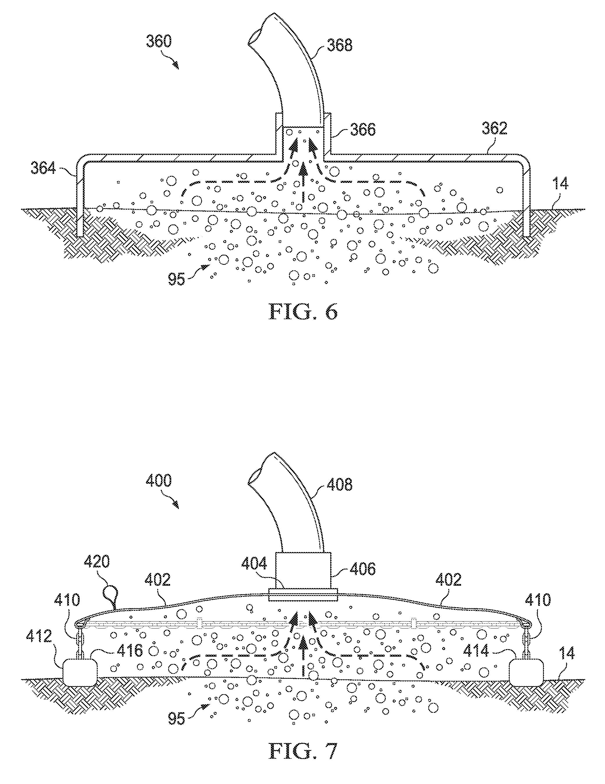
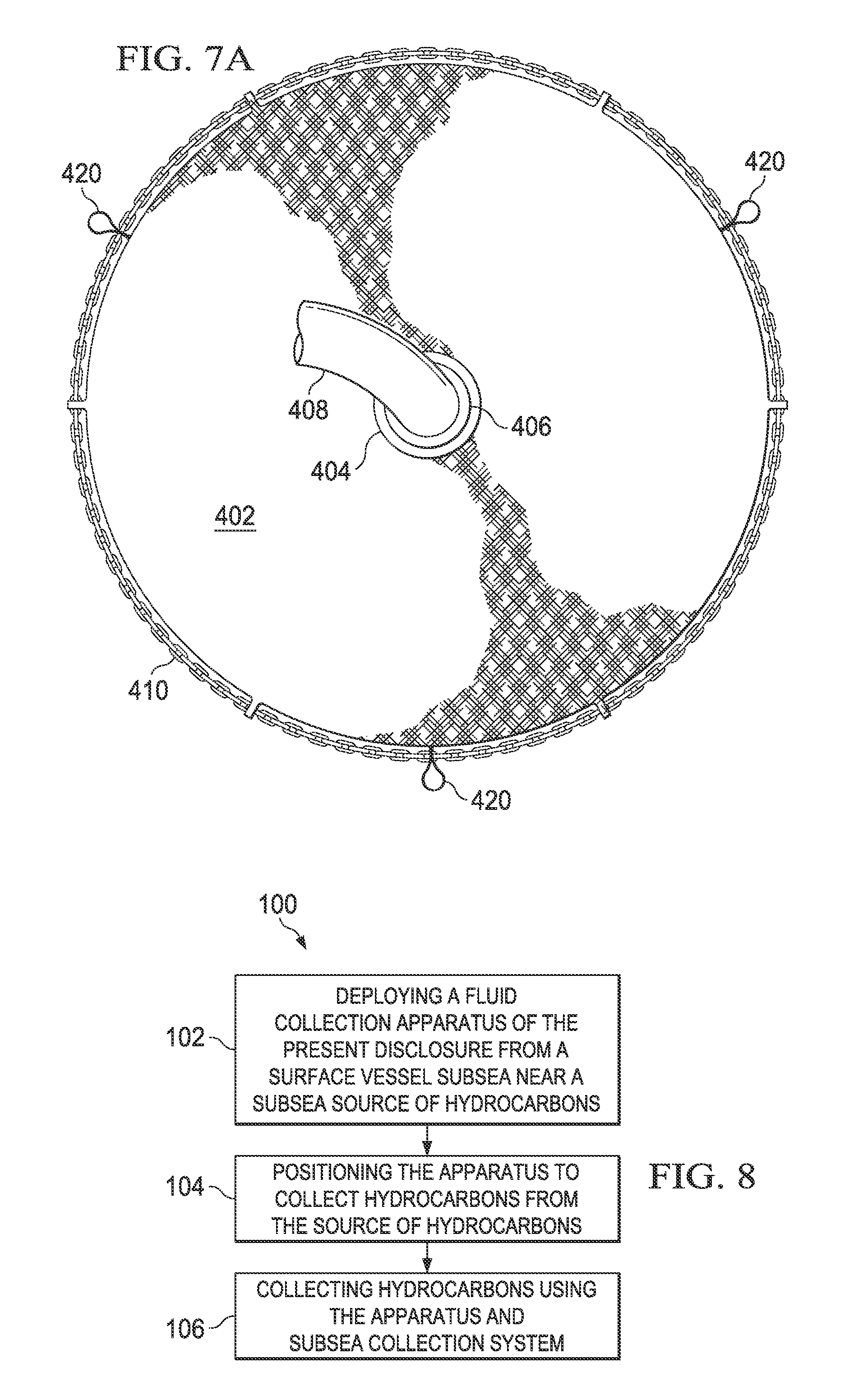
[0075] FIGS. 6 and 7 are schematic side elevation views of two other seal head embodiments that may be useful in certain apparatus and method embodiments of the present disclosure. FIG. 6 illustrates an embodiment 360 comprising a solid cover 362 having a peripheral skirt 364 that penetrates a distance into the seafloor, or in certain embodiments sets on the seafloor. A nozzle 366 collects hydrocarbons and/or other material 95 bubbling from up from seafloor 14 and routes the hydrocarbons and/or other material into a conduit 368, which fluidly connects to a movable member (not illustrated in FIG. 6) such as movable member 160 illustrated schematically in FIG. 5. Cover 362 and peripheral skirt 364 may be metal, plastic, fiberglass reinforced plastic (FRP) and the like. Embodiment 400, illustrated schematically in FIG. 7, is similar to embodiment 360, but rather than a solid cover and skirt, includes a flexible yet sturdy fabric 402 having a chain 410, and weights 414, 416, to collect hydrocarbons and/or other material seeping up from seafloor 14. A flange 404 and nozzle 406 arrangement, operably and fluidly connect fabric 402 to a conduit 408, which in turn routes hydrocarbons and/or other material collected by fabric 402 to a movable member (not illustrated) such as movable member 160 illustrated schematically in FIG. 5. Fabric 402 may comprise any number of plastic and/or textile materials. One of many suitable fabrics that may used are the flexible fabrics used in flexible storage tanks known under the trade designation Big Red Flexitank, which are multilayer plastics, and are described in U.S. published patent application 2010/0122981, which also describes compression flanges and nozzles useful with such fabrics. FIG. 7A illustrates a schematic plan view of embodiment 400, illustrating chain 410 extending around the periphery of fabric. This is but one possible arrangement; chain 410 could be spaced away from the periphery of fabric 402 several centimeters, or several tens of centimeters. Another optional feature, one or more loops 420, may be provided to allow an underwater vehicle such as an ROV to grasp chain 410 and position fabric 402 where desired.
[0076] FIGS. 8 and 9 are logic diagrams of two method embodiments in accordance with the present disclosure. The method of embodiment 100 of FIG. 8 is a method of establishing flow of material from a subsea source through a collection tool and a riser that ties back to a surface vessel, which may be a drill ship such as a Mobile Offshore Drilling Unit (MODU) equipped with a flare and hydrocarbon processing equipment with or without oil storage and oil transfer equipment to another vessel. In embodiment 100 the method comprises deploying a fluid collection apparatus from a surface vessel subsea near a subsea source of hydrocarbons, the apparatus comprising a collection tool of this disclosure, box 102. Method embodiment 100 then comprises positioning the apparatus to collect hydrocarbons from the source of hydrocarbons, box 104, and collecting hydrocarbons using the apparatus and subsea collection system, box 106.
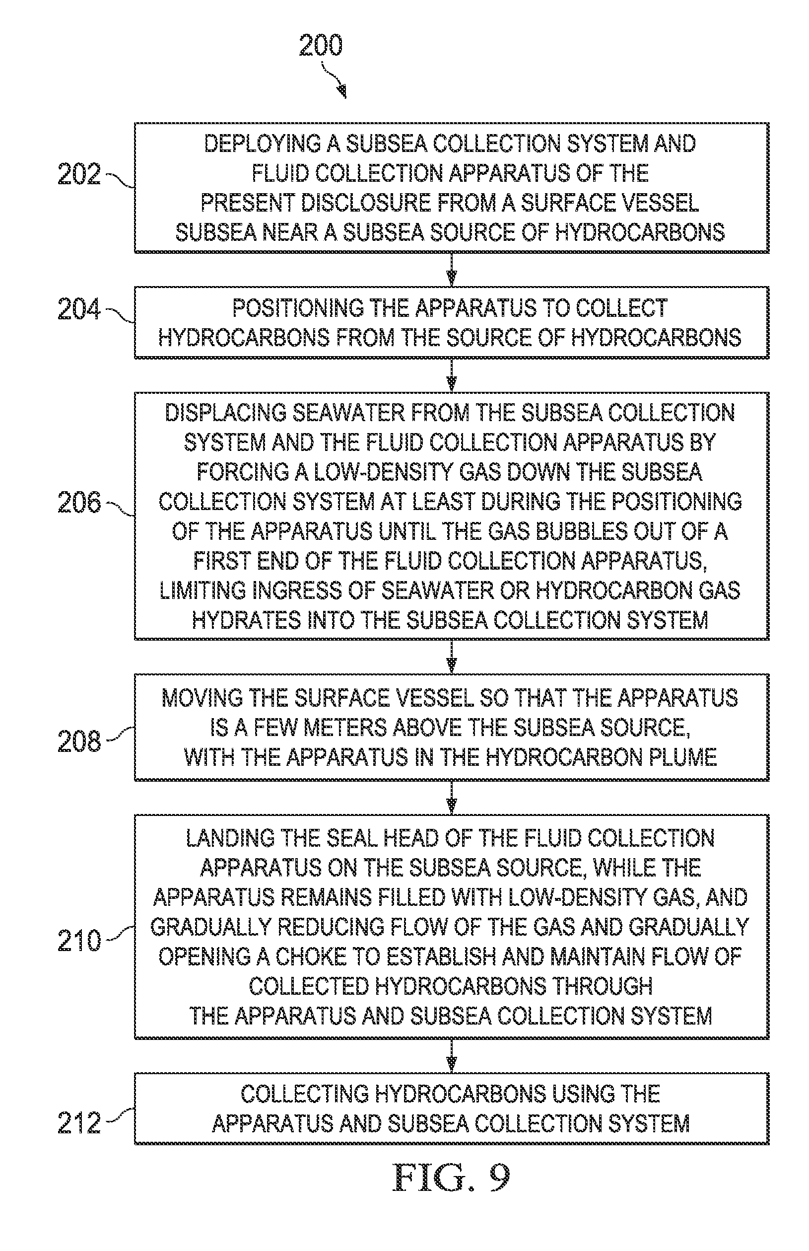
[0077] Another method of this disclosure is presented in the logic diagram of FIG. 9 as embodiment 200. Embodiment 200 comprises deploying a subsea collection system and a fluid collection apparatus from a surface vessel subsea near a subsea source of hydrocarbons, the apparatus comprising a collection tool of this disclosure, box 202. Method embodiment 200 then comprises positioning the apparatus to collect hydrocarbons from the source of hydrocarbons, box 204. Method 200 then comprises displacing seawater from the subsea collection system and apparatus by forcing a low-density gas down the subsea collection system at least during the positioning of the apparatus until the gas bubbles out of a first end of the seal head of the fluid collection apparatus, limiting ingress of seawater or hydrocarbon gas hydrates into the subsea collection system and apparatus thus limiting plugging of the subsea collection system and apparatus, box 206; moving the surface vessel so that the apparatus is a few meters above the subsea source, with the apparatus in the hydrocarbon plume, box 208; landing the seal head on the subsea source, while the apparatus remains filled with low-density gas, and gradually reducing flow of the gas and gradually opening a choke to establish and maintain flow of collected hydrocarbons through the apparatus and subsea collection system, box 210; and collecting hydrocarbons using the apparatus and subsea collection system, box 212.
[0078] In certain method embodiments, one or more inhibitor liquids may be introduced into or in the vicinity of the collection tool, the one or more inhibitor liquids selected from the group consisting of wax inhibitors, asphaltene inhibitors, scale inhibitors, corrosion inhibitors, antideposition agents, combinations of two or more thereof, and the like. One or more dispersant chemicals may also be introduced into or in the vicinity of the tool. Suitable corrosion inhibitors include, but are not limited to, compositions selected from the group consisting of amides, quaternary ammonium salts, rosin derivatives, amines, pyridine compounds, trithione compounds, heterocyclic sulfur compounds, alkyl mercaptans, quinoline compounds, polymers of any of these, and mixtures thereof. Suitable scale inhibitors include, but are not limited to, compositions selected from the group consisting of phosphate esters, polyacrylates, phosphonates, polyacrylamides, polysulfonated polycarboxylates, copolymers thereof, and mixtures thereof. These scale and corrosion inhibitors are more fully discussed in U.S. Pat. No. 7,772,160, assigned to Baker Hughes Inc., Houston, Tex., USA. Suitable asphaltene inhibitors include, but are not limited to, ester and ether reaction products, such esters formed from the reaction of polyhydric alcohols with carboxylic acids; ethers formed from the reaction of glycidyl ethers or epoxides with polyhydric alcohols; and esters formed from the reaction of glycidyl ethers or epoxides with carboxylic acids, as described in U.S. Pat. No. 6,313,367, also assigned to Baker Hughes. In certain embodiments, a chemical may contribute more than one of the functions of wax, corrosion, and scale inhibition, and dispersant action. As noted in the '367 patent, some of the compositions taught therein may function as asphaltene deposition inhibitors and dispersants.
[0079] Flow rates of the chemicals depend greatly on the specific situations, and one would not normally use more than required to perform one or more of the intended tasks. In general, the use of hydrate inhibitor is recommended to range from 0.5 to about 1.0 volumes of inhibitor chemical to volume of water that is expected to mix with hydrocarbon. For embodiments of collection tools of the present disclosure, flow rate of hydrate inhibitor such as methanol might range from about 2 to about 15 gallons per minute, or from about 6 to about 8 gallons per minute.
[0080] An alternative is to reduce or eliminate seawater mixing with hydrocarbons. There are several options to prevent mixing in a situation such as presented in FIG. 3, including inserting a hose with an expanding bladder around it to seal annulus 60 (bladders may be off the shelf items, such as used in packers), and inserting a mud or cement seal.
[0081] If hydrocarbons do escape the collection tool, dispersants may be helpful in certain embodiments. Dispersants are mixtures of solvents, surfactants and other additives that break up the surface tension of an oil slick or sheen and make oil more soluble in water. Dispersants do not remove oil from the water, but break up the oil slick into small droplets. These droplets disperse into the water column (or depths), where they may then break down further in the environment. Examples of dispersants that may be useful in the methods and systems disclosed herein are the chemical compositions known under the trade designations COREXIT 9500 and COREXIT 9527, available from Nalco Company, Naperville, Ill., USA, the compositions of which are publicly available and found in Table 1.
TABLE-US-00001 TABLE 1 Ingredients in COREXIT .RTM. 9500 and 9527 brand dispersants CAS Registry Number Chemical Name 57-55-6 1,2-Propanediol 111-76-2 Ethanol, 2-butoxy-* 577-11-7 Butanedioic acid, 2-sulfo-, 1,4-bis(2-ethylhexyl) ester, sodium salt (1:1) 1338-43-8 Sorbitan, mono-(9Z)-9-octadecenoate 9005-65-6 Sorbitan, mono-(9Z)-9-octadecenoate, poly(oxy- 1,2-thanediyl) derivs. 9005-70-3 Sorbitan, tri-(9Z)-9-octadecenoate, poly(oxy- 1,2-ethanediyl) derivs 29911-28-2 2-Propanol, 1-(2-butoxy-1-methylethoxy)- 64742-47-8 Distillates (petroleum), hydrotreated light *Note: This chemical component is not included in the composition of COREXIT 9500.
[0082] Collection tools in accordance with the present disclosure may be deployed by a surface vessel or MODU that includes facilities for deploying tubulars. During deployment, the tool may be hanging under the vessel, supported by the tubing that, in certain embodiments, is drill pipe for robustness, although the use of drill pipe is not required; for example, vacuum-insulated tubing may be used in certain embodiments if thermal insulation to prevent hydrates is considered. The tool is brought over the end of the leaking riser. The vessel rotates the tool to align the apertures with the damaged riser and drill pipe. As the tool is lowered it penetrates the mud as the tubing (drill pipe riser or other) is slackened. Drill collars may be added in the tubing line to increase mud penetration.
[0083] During start-up, if not self-starting, nitrogen or other low-density fluid may be injected into the top of tubing 4 to displace the seawater out of the riser 4 and establish flow of material up the tool and riser. The top of the tubing 4 is opened to the processing equipment in the surface vessel. The oil and gas, having lower density compared to seawater, induces flow of the produced fluid to the processing equipment. Optionally, gas lift or pumping may be provided. During normal operation, the vessel stays on location. An ROV may be used to monitor the bottom of pipe 4. One or more holes placed about 1 inch (2.54 cm) from the bottom of pipe 4 may be used as a way to monitor that the nitrogen or other low-density fluid is flowing all the way to the bottom of tubing 4 and to reduce the losses.
[0084] In an emergency disconnect situation, a surface vessel having the capability to lift the collection tool and riser up is used. If the surface vessel cannot lift the collection tool because of a vessel malfunction, weather, or other reason, the bottom part of the tool (seal head and seal head extension) may be dragged on the sea floor. If it snags something on the sea floor, nylon lines 34 (FIG. 2) may be provided that will break.
[0085] The chimney effect of seal head extension 18 may affect operations, as the venturi effect may induce water to enter through the apertures at the bottom of seal head 20. To offset this, the pressure differential is kept low by a relatively short chimney (seal head extension 18). Improved sealing around the apertures in seal head 20 may be provided, for example using flexible fabrics, such as any number of plastic and/or textile materials, and the like, as known by one of skill in the art. Gravel bags or just gravel may be placed on the mud floor around the damaged riser and seal head to form a partial seal and help prevent water from mixing with the collected fluids.
[0086] Methods of this disclosure where one or more functional fluids are used in the tool in conjunction with a low-density fluid being forced down the riser, and optionally a dispersant chemical (which may or may not have hydrate inhibition function), may limit formation of hydrocarbon gas hydrates, whereas methods of using only a low-density fluid forced down the riser (and tool, if present during deployment) and optionally a dispersant, may control hydrocarbon gas hydrate formation. In the latter methods, the risk of hydrate formation is higher, but the form of the hydrate can be controlled to a manageable level by preventing flakes of hydrates forming drifts, or hard compactions of hydrocarbon gas hydrates.
[0087] It should be noted that other vessels may be present during containment and production operations. For example, separate ship-based floating production and storage systems on the sea surface may be present, as well as processing vessels, collection vessels, service vessels, and the like. Other vessels may be provided for subsea installation, operational and ROV assistance, and hydrate prevention and remediation, if needed. A multipurpose intervention vessel may be present, which may include various subsea connector conduits, umbilicals from chemical dispersant and hydrate inhibition systems; a hydrate inhibition system service vessel which may also supply power and/or hydraulic assistance through one or more umbilicals; a subsea umbilical distribution box, and electrical power and/or hydraulic umbilical lines.
[0088] Methods of this disclosure may employ a riser positioning system and riser tension monitoring sub-system. A riser positioning system typically comprises a riser position clamp and a pair of acoustic sources or beacons. Suitable acoustic beacons are available from Sonardyne International Ltd in the UK, and from Sonardyne Inc., Houston, Tex. The riser position clamp with two acoustic beacons may be deployed anywhere on the riser. These beacons may be integrated with the containment vessel dynamic positioning (DP) systems in order to provide relative location of the top of the riser that may be fed directly into the management of vessel station-keeping limits. The riser tension monitoring unit may be strain-based and may be installed anywhere along the length of the riser, and in multiple locations.
[0089] In certain embodiments, certain connections may be expected to experience heavy fatigue. The teachings of Shilling, et al., "Development of Fatigue Resistant Heavy Wall Riser Connectors For Deepwater HPHT Dry Tree Riser Systems", OMAE2009-79518, may be useful in these embodiments.
[0090] The collection tools and methods of the present disclosure may be scalable over a wide range of water depths, well pressures and conditions. The riser 4 ideally will be capable of handling over 40,000 bbls per day (about 4800 cubic meters per day) with a 6-inch (15 cm) ID flow path in the riser. The riser joints may for example comprise 0.563-inch (1.430 cm) wall thickness X-80 steel material rated to 6,500 psi (45 MPa). In the past, X-80 material was used in order to successfully weld on premium riser connectors that had external and internal metal-to-metal seals and met the fatigue performance requirements of the anticipated service life. (X-80, or X80, is a number associate with American Petroleum Institute (API) standard 5 L.)
[0091] In general, riser 4 may have an outer diameter (OD) ranging from about 1 inch up to about 50 inches (2.5 cm to 127 cm), or from about 2 inches up to about 40 inches (5 cm to 102 cm), or from about 4 inches up to about 30 inches (10 cm to 76 cm), or from about 6 inches up to about 20 inches (15 cm to 51 cm).
[0092] From the foregoing detailed description of specific embodiments, it should be apparent that patentable collection tools and methods have been described. Although specific embodiments of the disclosure have been described herein in some detail, this has been done solely for the purposes of describing various features and aspects of the methods and certain apparatus used with those methods, and is not intended to be limiting with respect to the scope of the appended claims. It is contemplated that various substitutions, alterations, and/or modifications, including but not limited to those implementation variations which may have been suggested herein, may be made to the described embodiments without departing from the scope of the appended claims.
* * * * *
D00000
D00001
D00002
D00003
D00004
D00005
D00006
D00007
D00008
XML
uspto.report is an independent third-party trademark research tool that is not affiliated, endorsed, or sponsored by the United States Patent and Trademark Office (USPTO) or any other governmental organization. The information provided by uspto.report is based on publicly available data at the time of writing and is intended for informational purposes only.
While we strive to provide accurate and up-to-date information, we do not guarantee the accuracy, completeness, reliability, or suitability of the information displayed on this site. The use of this site is at your own risk. Any reliance you place on such information is therefore strictly at your own risk.
All official trademark data, including owner information, should be verified by visiting the official USPTO website at www.uspto.gov. This site is not intended to replace professional legal advice and should not be used as a substitute for consulting with a legal professional who is knowledgeable about trademark law.