Process And System For Treating Produced Water And Flowback Water From Oil And Gas Operations
Olson; Stephen W. ; et al.
U.S. patent application number 13/533632 was filed with the patent office on 2012-12-27 for process and system for treating produced water and flowback water from oil and gas operations. Invention is credited to Benjamin R. Earl, Stephen W. Olson, Daniel N. Ziol.
| Application Number | 20120325469 13/533632 |
| Document ID | / |
| Family ID | 47360738 |
| Filed Date | 2012-12-27 |

| United States Patent Application | 20120325469 |
| Kind Code | A1 |
| Olson; Stephen W. ; et al. | December 27, 2012 |
PROCESS AND SYSTEM FOR TREATING PRODUCED WATER AND FLOWBACK WATER FROM OIL AND GAS OPERATIONS
Abstract
A system and method for treatment of flowback water and produced water at an oil or gas wellhead includes a modular treatment facility that may be installed at a well site. The modular treatment facility includes separate and interchangeable modules that remove undesirable contaminants. The modules may be removed and replaced with similar modules when they are no longer effective at removing the contaminants. The spent modules may be transported to a regeneration center to be regenerated and transported back to a modular treatment facility.
| Inventors: | Olson; Stephen W.; (Pasadena, CA) ; Earl; Benjamin R.; (Laguna Beach, CA) ; Ziol; Daniel N.; (Pasadena, CA) |
| Family ID: | 47360738 |
| Appl. No.: | 13/533632 |
| Filed: | June 26, 2012 |
Related U.S. Patent Documents
| Application Number | Filing Date | Patent Number | ||
|---|---|---|---|---|
| 61501643 | Jun 27, 2011 | |||
| Current U.S. Class: | 166/267 ; 166/75.12 |
| Current CPC Class: | C02F 2101/203 20130101; C02F 2303/16 20130101; C02F 9/00 20130101; E21B 43/40 20130101; C02F 1/5245 20130101; C02F 1/42 20130101; C02F 2101/32 20130101; C02F 2101/101 20130101; C02F 2103/10 20130101; C02F 1/66 20130101; C02F 2101/006 20130101; C02F 2201/007 20130101; C02F 2101/206 20130101 |
| Class at Publication: | 166/267 ; 166/75.12 |
| International Class: | E21B 43/40 20060101 E21B043/40; E21B 21/06 20060101 E21B021/06 |
Claims
1. A method for treating water discharged from oil and/or gas drilling and/or fracturing operations at a well site, the method comprising: providing a docking station at the well site; mounting a plurality of replaceable processing modules to the docking station; providing the discharged water to the docking station; and processing the discharged water by passing it through the processing modules for reducing contaminants from said discharged water.
2. The method as recited in claim 1, further comprising: removing the used processing modules from the docking station; and reconditioning said used modules.
3. The method as recited in claim 2, wherein removing the used processing modules comprises removing the used processing modules periodically.
4. The method as recited in claim 2, wherein removing the used processing modules comprises removing the used processing modules after they have been used to process a certain amount of the discharged water.
5. The method as recited in claim 2, further comprising replacing said removed used processing modules with reconditioned modules.
6. The method as recited in claim 1, wherein providing said docking station comprises transporting the docking station to the well site.
7. The method as recited in claim 1, further comprising processing said discharged water through two organic removal treatment modules, two metals removal treatment modules and two sealant and selective salts removal modules.
8. The method as recited in claim 1, wherein processing the discharged water comprises processing the discharged water by passing it through at least some of the processing modules in series.
9. The method as recited in claim 8, wherein processing the discharged water further comprises processing the discharged water by passing it through at least some of the processing modules in parallel.
10. The method as recited in claim 1, wherein processing the discharged water comprises processing the discharged water by passing it through at least some of the processing modules in parallel.
11. The method as recited in claim 1, wherein said processing modules are modular filters.
12. The method as recited in claim 1, further comprising re-using the water after processing in oil and/or gas drilling and/or fracturing operations.
13. A system for treating water discharged from oil and/or gas drilling and/or fracturing operations at a well site, comprising: a docking station for receiving the discharged water; and a plurality of replaceable processing modules mounted to the docking station for receiving the discharged water from the docking station, each module configured to reduce one or more contaminants from the discharged water.
14. The system as recited in claim 13, wherein the docking station is transportable to the well site.
15. The system as recited in claim 13, wherein at least some of the plurality of replaceable processing modules are coupled to each other in series.
16. The system as recited in claim 13, wherein at least some of the plurality of replaceable processing modules are coupled to each other in parallel.
17. The system as recited in claim 16, wherein at least some of the plurality of replaceable processing modules are coupled to each other in series.
18. The system as recited in claim 13, wherein each module is a modular filter.
19. The system as recited in claim 13, further comprising a module regeneration facility configured for regenerating used modules.
20. The system as recited in claim 13, comprising two organic removal treatment modules, two metals removal treatment modules and two scalant and selective salts removal modules.
Description
CROSS-REFERENCE TO RELATED APPLICATION
[0001] The above referenced application claims priority to and is based upon U.S. Provisional Application No. 61/501,643 filed on Jun. 27, 2011, the contents of which are fully incorporated herein by reference.
BACKGROUND
[0002] Hydraulic fracturing has significantly increased access to and production of oil and natural gas in various locations throughout the United States. Shale deposits approximately two miles deep can be accessed by drilling vertically and then horizontally to the shale deposit which contains oil and/or natural gas once the vertical well bore has been drilled. The drilling operation is then redirected horizontally and subsequently drilled one to two miles through the center of the shale deposit. Once the well bore is drilled, the horizontal portion is perforated using explosive charges staged along the horizontal well bore.
[0003] After the well bore has been perforated, a significant amount of water (for example, up to 5,000,000 gallons) carrying chemicals, sand, ceramic beads, and gels are injected at very high pressure to create fissures in the shale deposit. These fissures are propped open by the sand and ceramic beads. This allows gas and oil to be released from the fissures. Following injection of the liquid, approximately 20% of the liquid returns to the surface in the first 7 to 14 days. This water (known as "flowback water") has concentrations of organics (oil and grease), metals (iron and manganese), sealants (calcium and sulfates) and salts. After the initial discharge of flowback water, the well continues to produce oil and "produced water" which is similar in composition to flowback water, but higher in concentration of salts.
[0004] Well drillers often import water from fresh water sources in 120 barrel tanker trucks (approximately 5,000 gallon capacity). Because of the weight of trucks and the fragile road conditions, trucks are often only allowed to transport at 50% load capacity. While distance from water source to well site varies, one-way trips in excess of 30 miles are not uncommon. There can also be significant wait time when both loading and unloading the trucks. A typical hydraulic fracturing operation consumes 4 million gallons of water or 1,600 to 2,000 tanker trucks at 50% capacity.
[0005] Once the well has been drilled and hydraulically fractured, flow back is produced at the well, and is about 20% of the input volume. The flow back water (and later, the produced water) is collected and transported offsite to an injection well (e.g., disposal well), typically 30 or more miles away. In addition to wells created by fracturing, other oil and gas wells also release produced water. The flowback water and produced water are generally not treated prior to transportation, and thus, are filled with contaminants, making transportation more hazardous. Prior to injection, the water is often treated with biocides and scale inhibitors so that the water does not clog or contaminate the disposal well site. This current model is expensive, as trucking costs are expensive, is destructive to existing roads, and is potentially dangerous because of traffic incidents and the potential of hazardous spills.
SUMMARY
[0006] Embodiments of the present invention include a system and method for treatment of both flowback and produced water at the wellhead of oil and gas operations so that the treated water may be used by the drillers to drill new wells, for capping or shutting in a well, etc., thus reducing the amount of fresh water required. The system and method include a modular treatment facility that may be installed at the well site. Separate and interchangeable modules that remove undesirable contaminants (e.g., organics, metals, sealants, salts, and radionuclides) are placed in the onsite treatment facility and removed and replaced with similar modules. After water flows through the modular treatment, it will be suitable for reuse in a future hydraulic fracturing operation. This will significantly reduce or eliminate the usual transportation of contaminated liquids to an injection well or remote treatment facility. The modular design allows for continuous operation at the well site, as the treatment modules may be replaced and the spent modules may be transported to a central treatment location to be regenerated and transported back to another well site. This significantly reduces or eliminates the necessity of transporting contaminated liquids or liquid chemicals. The process can rely solely on well head pressure for operational energy, thus reducing or eliminating the need for a separate power source and reducing the potential of spark induced explosions.
[0007] In an exemplary embodiment a method for treating water discharged from oil and/or gas drilling and/or fracturing operations at a well site is provided. The method includes providing a docking station at the well site, mounting a plurality of replaceable processing modules to the docking station, providing the discharged water to the docking station, and processing the discharged water by passing it through the processing modules for reducing contaminants from the discharged water. In another exemplary embodiment, the method further includes removing the used processing modules from the docking station, and reconditioning the used modules. In yet another exemplary embodiment, removing the used processing modules includes removing the used processing modules periodically. In a further exemplary embodiment, removing the used processing modules includes removing the used processing modules after they have been used to process a certain amount of the discharged water. In yet a further exemplary embodiment, the method also includes replacing the removed used processing modules with reconditioned modules. In one exemplary embodiment, providing the docking station includes transporting the docking station to the well site. In another exemplary embodiment, the method also includes processing the discharged water through two organic removal treatment modules, two metals removal treatment modules and two sealant and selective salts removal modules. In yet another exemplary embodiment, processing the discharged water includes processing the discharged water by passing it through at least some of the processing modules in series. In a further exemplary embodiment, processing the discharged water includes processing the discharged water by passing it through at least some of the processing modules in parallel. In yet a further exemplary embodiment, processing the discharged water includes processing the discharged water by passing it through at least some of the processing modules in parallel and at least through some of the modules in series. In an exemplary embodiment, the processing modules are modular filters. In a further exemplary embodiment, the method also includes re-using the water after processing in oil and/or gas drilling and/or fracturing operations.
[0008] In another exemplary embodiment, a system for treating water discharged from oil and/or gas drilling and/or fracturing operations at a well site is provided. The system includes a docking station for receiving the discharged water, and a plurality of replaceable processing modules mounted to the docking station for receiving the discharged water from the docking station. Each module is configured to reduce one or more contaminants from the discharged water. In yet another exemplary embodiment, the docking station is transportable to the well site. In a further exemplary embodiment, at least some of the plurality of replaceable processing modules are coupled to each other in series. In another exemplary embodiment, at least some of the plurality of replaceable processing modules are coupled to each other in parallel. In yet another exemplary embodiment, at least some of the plurality of replaceable processing modules are coupled to each other in series and at least some of the plurality of replaceable processing modules are coupled to each other in parallel. In one exemplary embodiment, each module is a modular filter. In another exemplary embodiment, the system also includes a module regeneration facility configured for regenerating used modules. In yet a further exemplary embodiment, the system includes two organic removal treatment modules, two metals removal treatment modules and two sealant and selective salts removal modules.
BRIEF DESCRIPTION OF THE DRAWINGS
[0009] FIG. 1 is a schematic view of an exemplary modular treatment facility.
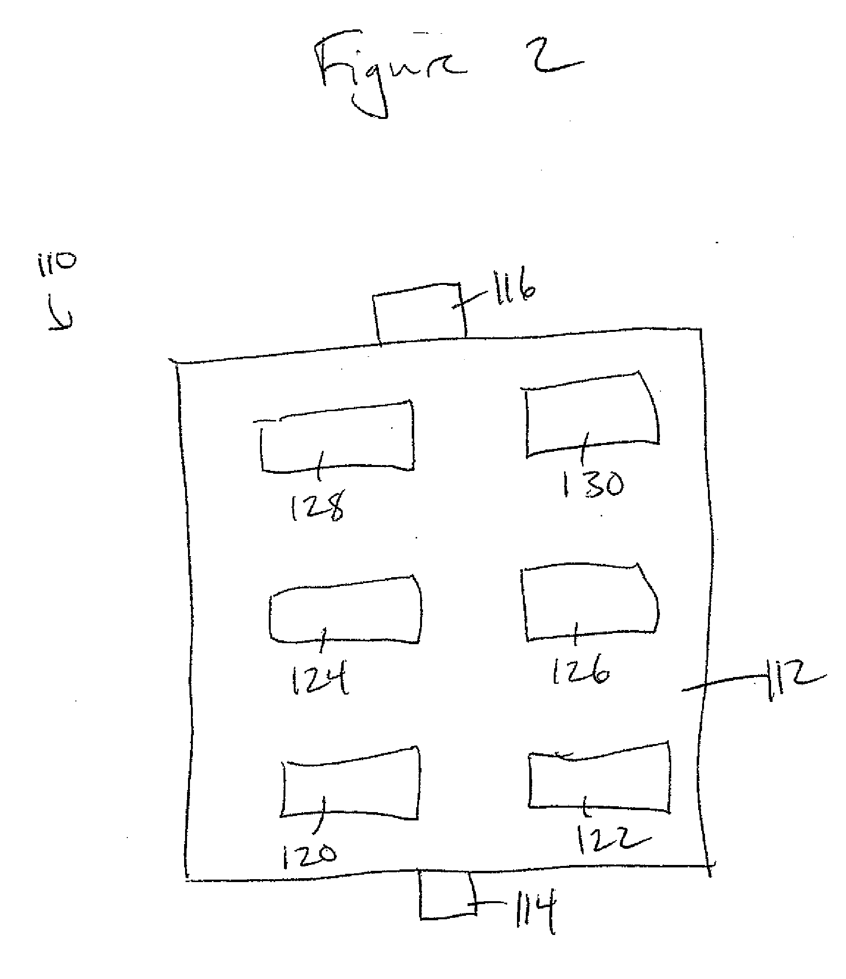
[0010] FIG. 2 is a schematic view of another exemplary modular treatment facility.
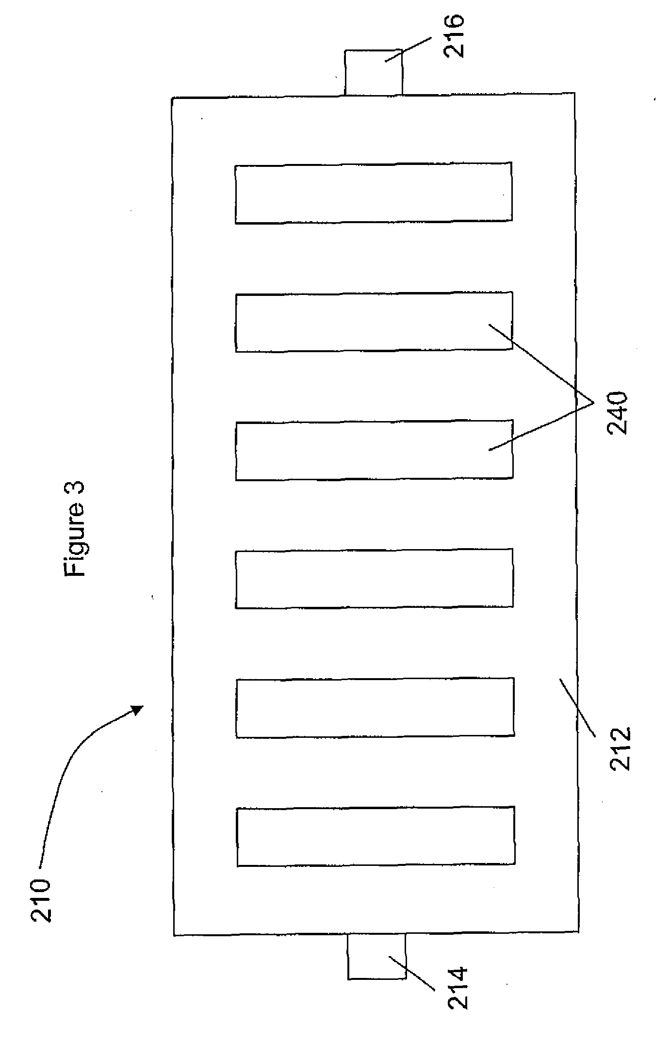
[0011] FIG. 3 is a top view of an exemplary modular treatment facility with the modules removed.
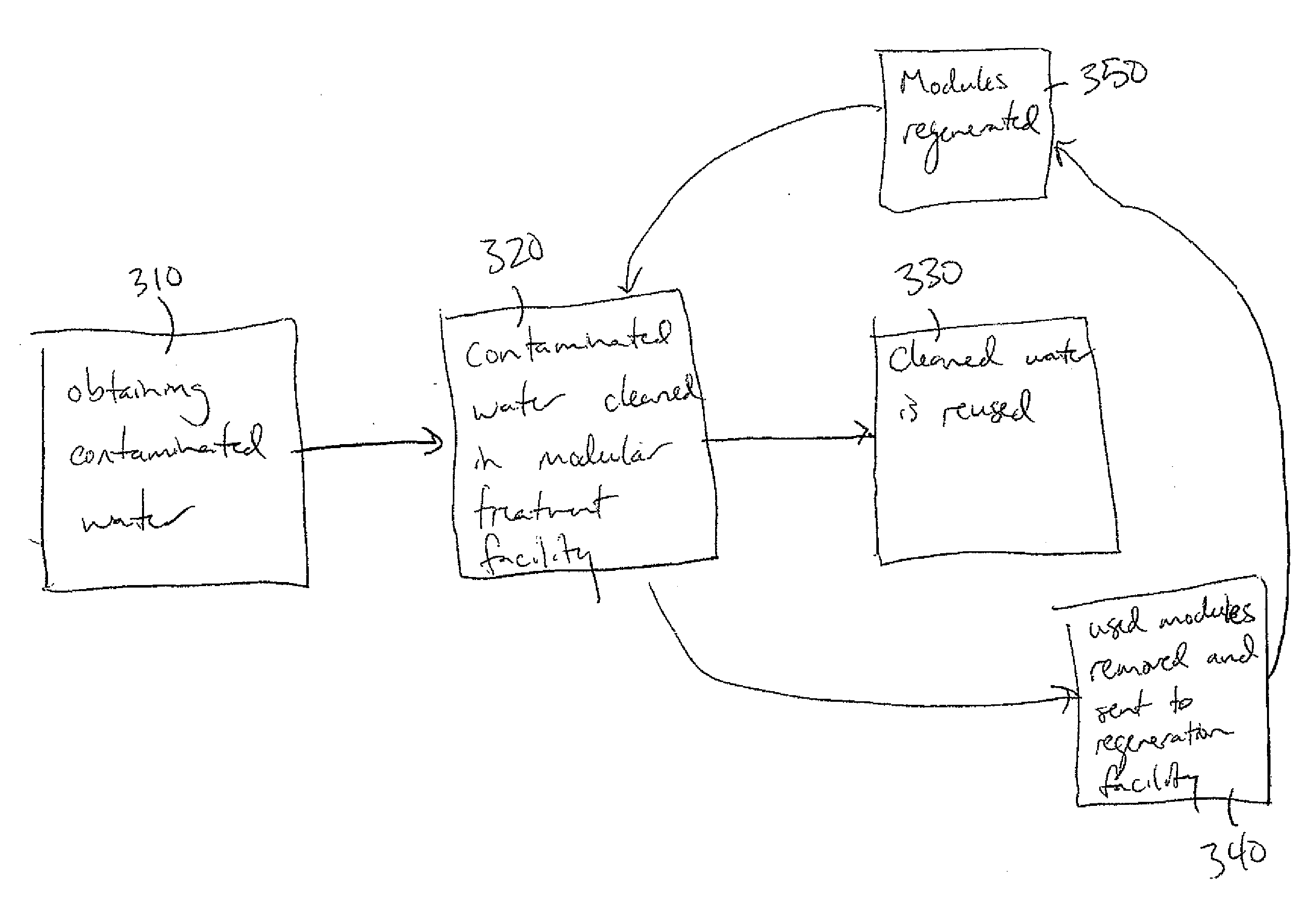
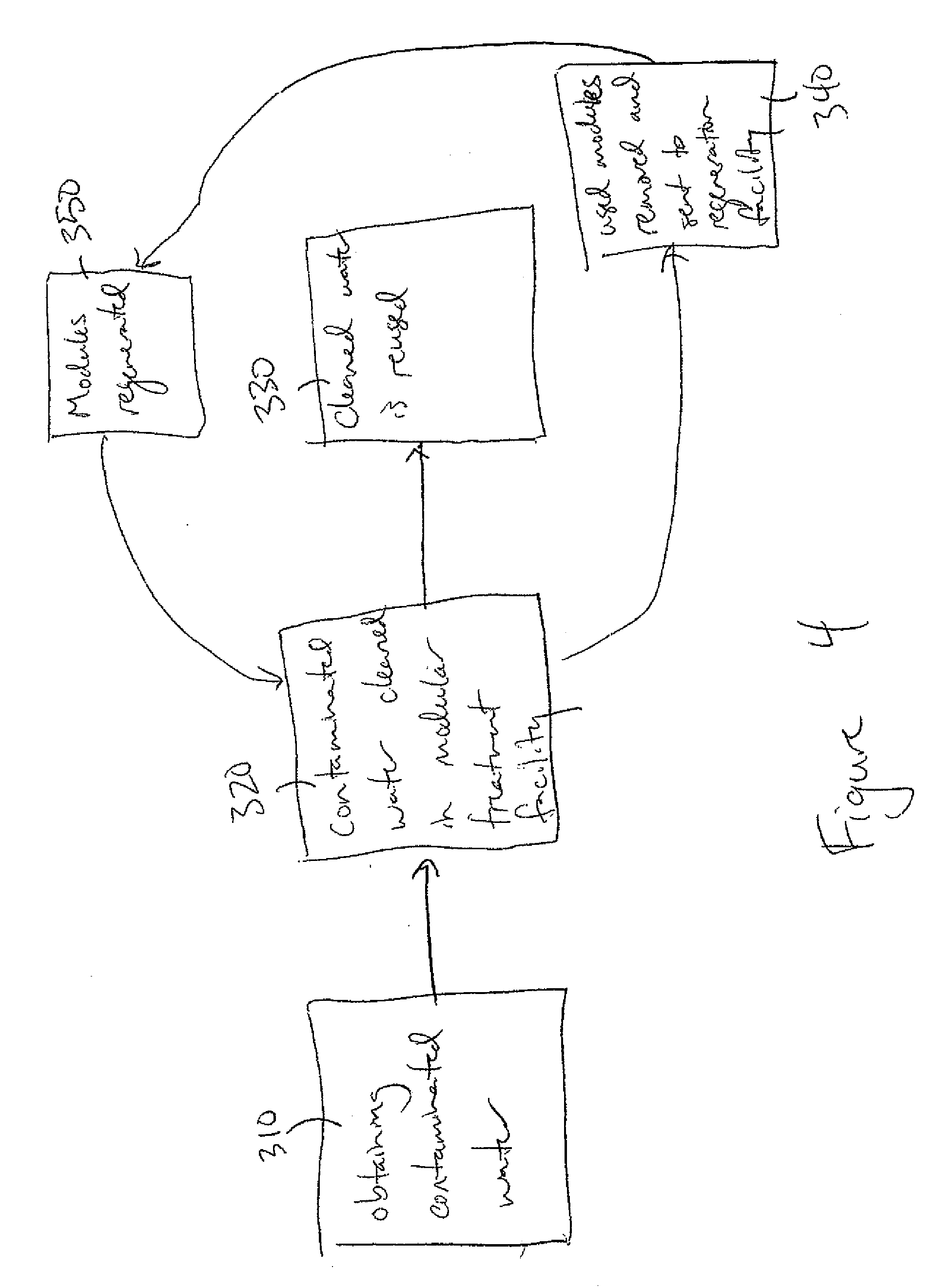
[0012] FIG. 4 is a flow chart depicting a method of the present invention.
DETAILED DESCRIPTION
[0013] Embodiments of the present invention include a system and method for treatment of both flowback and produced water at the wellhead of oil and gas operations so that the treated water may be used by the drillers to drill new wells, for capping or shutting in a well, etc., thus reducing the amount of fresh water required. The system and method include a modular treatment facility that may be installed at the well site. The modular treatment facility includes separate and interchangeable modules that remove undesirable contaminants (e.g., organics, metals, sealants, salts, and radionuclides). The modules are containers that are configured to remove particular contaminants. The modules may be removed and replaced with similar modules when they are no longer effective at removing the contaminants. The spent modules may be transported to a central treatment location to be regenerated and transported back to a modular treatment facility.
[0014] The modular treatment facility is a semi-permanent treatment skid or docking station that can be placed on a well site between the producer's separator (which separates the oil or gas and water) and storage tanks (which stores the flowback and produced water). However, the modular treatment facility may be placed in any suitable location near the wellhead. The water discharged from the separator is piped to the treatment skid. The treatment skid has ports to hold treatment modules, each of which is self-contained, and each of which can be removed and replaced. Each treatment skid can contain any number of treatment modules as desired. It may be preferable to have multiple similar treatment modules to allow for redundancy and to allow for online hot transfer (i.e., one module may be transferred for another like module without stopping the flow through the treatment skid). Depicted in FIG. 1 is an exemplary modular treatment facility 10. The modular treatment facility 10 includes a docking station 12, an inlet 14 at one end, and an outlet 16 at another end. The shown exemplary modular treatment facility 10 includes two treatment modules for each of three treatment processes. In FIG. 1, the modular treatment facility 10 includes two organics removal treatment modules 20 and 22 (e.g., oil removal modules), two metals removal treatment modules 24 and 26 (e.g., iron removal modules), and two sealant and selective salts removal modules 28 and 30 (e.g., sulfate removal modules). As shown in FIG. 1, the treatment modules may be connected in series, however, they may also be connected in parallel.
[0015] For example, as shown in FIG. 1, the treatment skid may include six modules in series: two organics removal treatment modules, two metals removal treatment modules, and two scalant and selective salts removal modules. Alternatively, as shown in FIG. 2, the treatment skid 112 may include two parallel systems, e.g., each including an organics removal treatment module 120 and 122, a metals removal treatment module 124 and 126, and a scalant and selective salts removal module 128 and 130. The parallel system increases the flow capacity of the system. Additionally, flow capacity can be improved by sequentially expanding the size of the modules in series.
[0016] The treatment skid may be passive, i.e., no outside power is required. In this instance, the treatment skid operates off the pressure produced by the well. That is, the flowback water and produced water exit the well under high pressure, thus when they are piped to the treatment skid, they are still under pressure. This pressure pushes the water through each treatment module, enabling the system to operate. The passive nature of the treatment skid reduces the possibility of fire due to sparks and reduces cost.
[0017] Each treatment skid may be optimized for a particular site. That is, the modules may be manufactured such that elements are selectively removed. For instance, it may be desirable to have some elements remain in the water after treatment, and the modules may be designed to remove most contaminants and remove some of or none of a particular element or compound (e.g., chlorine). Additionally, the modules may be optimized to remove the particular contaminants found at a site.
[0018] The modules may be formed to have minimal chemical usage, unlike conventional flowback treatment systems which often require extensive use of chemicals. As will be described below, in an embodiment of the present invention, chlorine tablets for use in a metal contaminant module (to oxidize the metal), may be the only hazardous chemicals used. However, chlorine tablets are relatively stable for transit and thus are safer than other chemicals used for water treatment. In addition, the modules may be closed modules. Therefore, no chemical handling is required on site. Rather, the modules may be manufactured and closed to prevent or reduce mishaps. In addition, the modules may be designed to enable dry unit transportation. That is, the modules, whether regenerated or spent, are substantially dry during transit. The dry modules reduce or eliminate spill risk as the contaminants are bound inside the modules.
[0019] The exemplary docking station has a multi-slot design as shown in FIG. 3. As shown in FIG. 3, the docking station 212 includes a slot 240 for each of the six modules shown in FIG. 1. However, a docking station can also include additional slots so that additional modules could be added as desired. The multiple slots allows for including multiples of each module, which enables online hot transfer, i.e., when two of the same modules are included, the spent module can be removed and replaced without stopping the flow, as the flow could, e.g., bypass the slot where the module has been removed. The modules could be replaced when used up using a spare module stored on site, or the modules could be replaced periodically. The docking station may be built so that the piping, aside from the inlet and outlet, is fully contained within the structure. Therefore, all pipes connecting modules may be fully enclosed within the station, for example, under the top surface of the skid. The docking station can be fully enclosed. This makes the system more secure from tampering. Additionally, an enclosed docking station protects the system from changing weather conditions. The system may also optionally include an alarm system. The alarm could be configured to make a notification when a module is used, when there is an error in a module, or when there is an error in the system. The alarm could be built into the docking station, or alternatively, built into individual modules.
[0020] The treatment modules could include modules for removing organics, metals, salts and scalants, radionuclides, and any other contaminants as desired. The modules may be separated or combined, e.g., separate modules for each type of contaminant, or a single module could be used for metal, salts, and scalants removal. Additionally, two different modules for salts and scalants removal could be used to remove different classes of contaminants.
[0021] Exemplary treatment modules include an organics module, a metals module, a salts and scalants module, and a radionuclides module. The organics module could be configured to remove oil using various absorptive media. Suitable absorptive media includes activated clay, activated carbon (e.g., granular activated carbon), and diatomaceous earth. The metals module could be configured to remove various metals, such as iron, aluminum, and other heavy metals using an oxidation process. The metals could be oxidized (e.g., using chlorine tablets) and then removed from the water using Greensand, manganese Greensand, or other suitable filtering methods. When the metals module is used subsequent to the organics module, chlorine is not added until after oil and other are removed, thus reducing chemical demand. The salts and scalants removal could be configured to selectively remove salts and scalants such as (sulfates and bicarbonates) using, e.g., pellet crystallization. The pellet crystallization occurs in a closed reactor, i.e., the closed module, and is a passive process that does not ordinarily require controls. In pellet crystallization, seed pellets are placed in the reactor and water containing like materials flows over the pellets and creates larger crystals. The salts and sealants removal could be designed to allow some salts or other compounds to remain in the water. For example, the chlorine added in the metals module could be allowed to remain in the water, thus providing water including chlorine, which could be used to arrest bacterial growth. The radionuclides module could be used to remove, e.g., radium, strontium, and other nuclides using conventional precipitation methods (e.g., yellow caking) or ion exchange methods (e.g., using fluorine based resins).
[0022] Once treatment modules have achieved optimal absorption at the well site, or are otherwise removed, they can be replaced with new or regenerated modules. Prior to removal from the well site, the modules may be dewatered by using air to blow out the water. For instance, the flow to the modular treatment facility may be shut down momentarily while air from a compressor (e.g., a compressor on a transport truck) is sent through the line, displacing the water. This results in modules that are substantially dry, enabling safer and more economical transportation. The removed modules are then transported to a centralized regeneration facility where they can be treated in a contained environment. The regeneration facility could be a large regeneration factory serving a large number of well sites, or alternatively, a smaller processing plant (e.g., a processing plant contained in a trailer) could be used to serve a single or small group of well sites. The regeneration facility has several benefits. Such a facility can operation in all weather conditions, and additionally, contains contaminants from release into the environment. The regeneration facility allows for bulk handling of materials and byproducts and reduces the number of critical staff required, all of which help to reduce cost. The regeneration facility also reduces permitting requirements. Compared to trucking large amounts of water to well sites and from well sites to disposal, a centralized regeneration facility significantly reduces transportation exposure. One truck or other vehicle can carry multiple modules from multiple sites, reducing the number of times a vehicle must return to the regeneration facility. These simplifications reduce the net number of highway miles that must be traveled to handle produced well water byproducts. In addition, the regeneration facility reduces risk to the environment and personnel and enhances recovery ability. Generally, no (or minimal) site cleanup is required at the well site, as the used modules may simply be removed and transported to the facility. Personnel at the well site are generally not exposed to hazardous byproducts, as the docking station and modules are contained. The online hot transfer capability of the system reduces or eliminates the amount of down time at the well site. The modules may then be rehabilitated at the central plant in a controlled environment, thus the materials and chemicals are contained in a secure environment. In addition, the modules may be formed to include salvageable materials, i.e., the materials themselves may be regenerated so they can be used again in another module. A smaller on-site processing plant has many of these benefits, but has a reduced capacity.
[0023] The various modules described above may be regenerated using known methods. For instance, for the above described organics module, a kiln may be used to remove the volatile organics from the absorptive media. Minimum start-up fuel is required, at which point, combustion of the volatile organics is self-powered. The waste heat that is generated may be reused. In addition, contrary to conventional organics removal which requires the use of chemicals and creates a type of sludge, the above regeneration method uses less chemicals (e.g., it uses a small amount of fuel to start up and maintain combustion) and results in a solid byproduct. For the above described metals module, the Greensand may be reconditioned by backwashing, i.e., pressurized water is directed over the used Greensand. The backwashing could occur either inside or outside of the module. The water used for backwashing could then be filtered and pressed to remove the metal oxides by using known filtration methods, such as gravity filtration. After being filtered, the water could be reused for backwashing Greensand or other purposes. For the above described salts and sealants module, the grown crystals can simply be removed and replaced with seed crystals. The grown salt crystals can then be resold. For the above described radionuclide module, the process could be disposable or regenerative. For example, the ion exchange resin could be regenerated through known means. The radionuclide byproduct may then be disposed of using conventional disposal (e.g., placed in brine and left in a dead well).
[0024] An exemplary method of treating water from a well site is shown in FIG. 4. The method includes obtaining water from a contaminated source, such as an oil or gas well 310. Next, the contaminated water is run through the above described modular treatment facility 320. Water that is cleaned through the modular treatment facility may then be used in fracturing operations, be used for capping or shutting in a well, or for other purposes 330. Modules may be removed from the modular treatment facility and sent to a regeneration facility 340. At the regeneration facility, modules are regenerated 350. The modules are then sent back for use in a modular treatment facility.
[0025] Although the present invention has been described and illustrated in respect to exemplary embodiments, it is to be understood that it is not to be so limited, since changes and modifications may be made therein which are within the full intended scope of this invention as hereinafter claimed.
* * * * *
D00000
D00001
D00002
D00003
D00004
XML
uspto.report is an independent third-party trademark research tool that is not affiliated, endorsed, or sponsored by the United States Patent and Trademark Office (USPTO) or any other governmental organization. The information provided by uspto.report is based on publicly available data at the time of writing and is intended for informational purposes only.
While we strive to provide accurate and up-to-date information, we do not guarantee the accuracy, completeness, reliability, or suitability of the information displayed on this site. The use of this site is at your own risk. Any reliance you place on such information is therefore strictly at your own risk.
All official trademark data, including owner information, should be verified by visiting the official USPTO website at www.uspto.gov. This site is not intended to replace professional legal advice and should not be used as a substitute for consulting with a legal professional who is knowledgeable about trademark law.