Cooling System
You; Peiai ; et al.
U.S. patent application number 13/294845 was filed with the patent office on 2012-12-27 for cooling system. This patent application is currently assigned to DELTA ELECTRONICS (SHANGHAI) CO., LTD.. Invention is credited to Gang Liu, Peiai You, Jinfa Zhang.
| Application Number | 20120325447 13/294845 |
| Document ID | / |
| Family ID | 45105949 |
| Filed Date | 2012-12-27 |


| United States Patent Application | 20120325447 |
| Kind Code | A1 |
| You; Peiai ; et al. | December 27, 2012 |
COOLING SYSTEM
Abstract
In one aspect of the present invention, a cooling system includes a cooling plate having a first surface and an opposite, second surface, a body portion defined between the first surface and the second surface, at least one channel formed in the body portion for a cooling fluid to flow therethrough, an inlet and an outlet in flow communications with the at least one channel for the cooling fluid to enter and exit the at least one channel, respectively. The inlet and the outlet are spatially separated by a distance. The at least one channel defines a flow path of the cooling fluid flowing from the inlet to the outlet through the at least one channel. The flow path has a path length substantially greater than the distance between the inlet and the outlet.
| Inventors: | You; Peiai; (Shanghai, CN) ; Liu; Gang; (Shanghai, CN) ; Zhang; Jinfa; (Shanghai, CN) |
| Assignee: | DELTA ELECTRONICS (SHANGHAI) CO.,
LTD. Shanghai CN |
| Family ID: | 45105949 |
| Appl. No.: | 13/294845 |
| Filed: | November 11, 2011 |
| Current U.S. Class: | 165/170 |
| Current CPC Class: | H01M 10/625 20150401; H01M 10/613 20150401; H05K 7/20927 20130101; F28F 3/12 20130101; H01M 10/6556 20150401; Y02E 60/10 20130101; F28F 3/048 20130101 |
| Class at Publication: | 165/170 |
| International Class: | F28F 3/14 20060101 F28F003/14 |
Foreign Application Data
| Date | Code | Application Number |
|---|---|---|
| Jun 23, 2011 | CN | 201110172490.X |
Claims
1. A cooling system, comprising: (a) a first cooling plate having a first surface, an opposite, second surface, a body portion defined between the first surface and the second surface, a concave channel recessed from the second surface and formed in the body portion for a cooling fluid to flow therethrough, an inlet and an outlet in flow communications with the channel for the cooling fluid to enter and exit the channel, respectively; and (b) a second cooling plate having a first surface and an opposite, second surface, wherein the second surface of the first cooling plate is adapted for mating with the first surface of the second cooling plate such that as assembled, the first cooling plate and the second cooling plate is fastened together to form a sealed enclosure between the second surface of the first cooling plate and the first surface of the second cooling plate enclosing the channel.
2. The cooling system of claim 1, wherein the inlet is engaged with one end of the channel and the outlet is engaged with the other end of the channel, and wherein the inlet and the outlet are spatially separated by a distance.
3. The cooling system of claim 2, wherein the channel is serpentinely formed to define a zig-zag flow path of the cooling fluid flowing from the inlet to the outlet through the channel, wherein the zig-zag flow path has a path length substantially greater than the distance between the inlet and the outlet.
4. The cooling system of claim 3, wherein the second cooling plate has a fin serpentinely protruding from the first surface thereof such that, when the first cooling plate and the second cooling plate are fastened together, the fin is placed in the channel.
5. The cooling system of claim 1, wherein the first surface of the second cooling plate is substantially flat.
6. The cooling system of claim 5, wherein the first cooling plate has a fin serpentinely protruding in the channel thereof.
7. The cooling system of claim 1, wherein the first surface of the first cooling plate is adapted for mounting at least one first electrical component thereon.
8. The cooling system of claim 1, wherein the second surface of the second cooling plate is adapted for mounting at least one second electrical component thereon.
9. A cooling system, comprising: (a) a first cooling plate having a first surface, an opposite, second surface, a body portion defined between the first surface and the second surface, a cavity recessed from the second surface and formed in the body portion, and a plurality of first fins protruding from a bottom of the cavity, the plurality of first fins being substantially parallel to each other to form a plurality of channels therebetween for a cooling fluid to flow therethrough, an inlet and an outlet in flow communications with the plurality of channels for the cooling fluid to enter and exit the plurality of channels, respectively; and (b) a second cooling plate having a first surface and an opposite, second surface, wherein the second surface of the first cooling plate is adapted for mating with the first surface of the second cooling plate such that as assembled, the first cooling plate and the second cooling plate is fastened together to form a sealed enclosure between the second surface of the first cooling plate and the first surface of the second cooling plate enclosing the cavity.
10. The cooling system of claim 9, wherein the inlet and the outlet are spatially separated by a distance.
11. The cooling system of claim 10, wherein each of the plurality of channels defines a respective flow path of the cooling fluid flowing from the inlet to the outlet through the corresponding channel, wherein the respective flow path has a path length substantially greater than the distance between the inlet and the outlet.
12. The cooling system of claim 10, wherein the inlet and the outlet are placed at two diagonal corners of the cavity.
13. The cooling system of claim 9, wherein the second cooling plate has a plurality of second fins protruding from the first surface thereof, wherein the plurality of second fins are substantially parallel to each other and positioned such that, when the first cooling plate and the second cooling plate are fastened together, the plurality of second fins inserts into the plurality of channels formed by the plurality of first fins.
14. The cooling system of claim 9, wherein the first surface of the second cooling plate is substantially flat.
15. The cooling system of claim 9, wherein the first surface of the first cooling plate is adapted for mounting at least one first electrical component thereon.
16. The cooling system of claim 9, wherein the second surface of the second cooling plate is adapted for mounting at least one second electrical component thereon.
17. A cooling system, comprising: a cooling plate having a first surface and an opposite, second surface, a body portion defined between the first surface and the second surface, at least one channel formed in the body portion for a cooling fluid to flow therethrough, an inlet and an outlet in flow communications with the at least one channel for the cooling fluid to enter and exit the at least one channel, respectively, wherein the inlet and the outlet are spatially separated by a distance, wherein the at least one channel defines a flow path of the cooling fluid flowing from the inlet to the outlet through the at least one channel, and wherein the flow path has a path length substantially greater than the distance between the inlet and the outlet.
18. The cooling system of claim 17, wherein the at least one channel is serpentinely formed to define a zig-zag flow path.
19. The cooling system of claim 17, further comprising a first plate having a first surface and an opposite, second surface, attached to the cooling plate such that the second surface of the first plate is substantially in contact with the first surface of the cooling plate.
20. The cooling system of claim 19, wherein the first surface of the first plate is adapted for mounting at least one first electrical component thereon.
21. The cooling system of claim 20, wherein the at least one first electrical component comprises a first power converter.
22. The cooling system of claim 17, further comprising a second plate having a first surface and an opposite, second surface, attached to the cooling plate such that the first surface of the second plate is substantially in contact with the second surface of the cooling plate.
23. The cooling system of claim 22, wherein the second surface of the second plate is adapted for mounting at least one second electrical component thereon.
24. The cooling system of claim 23, wherein the at least one second electrical component comprises a second power converter.
25. An electrical device, comprising the cooling system of claim 17.
26. The electrical device of claim 25, further comprising a first plate having a first surface and an opposite, second surface, attached to the cooling plate such that the second surface of the first plate is substantially in contact with the cooling system.
27. The electrical device of claim 26, wherein the first surface of the first plate is adapted for mounting at least one first electrical component thereon.
28. The electrical device of claim 25, further comprising a second plate having a first surface and an opposite, second surface, attached to the cooling plate such that the first surface of the second plate is substantially in contact with the cooling system.
29. The electrical device of claim 28, wherein the second surface of the second plate is adapted for mounting at least one second electrical component thereon.
30. The electrical device of claim 25, further comprising at least one first electrical component and at least one second electrical component, positioned such that the cooling system is sandwiched between the at least one first electrical component and the at least one second electrical component.
31. The electrical device of claim 30, wherein the at least one first electrical component and the at least one second electrical component are electrically connected to each other in series or in parallel.
Description
CROSS-REFERENCE TO RELATED PATENT APPLICATION
[0001] This application claims priority to and the benefit of, pursuant to 35 U.S.C. .sctn.119(a), Chinese patent application No. 201110172490.X, filed Jun. 23, 2011, entitled "COOLING SYSTEM", by Peiai You et al., the content of which is incorporated herein by reference in its entirety.
FIELD OF THE INVENTION
[0002] The present invention relates to a cooling system, and more particularly, to a cooling system sandwiched between two electrical modules.
BACKGROUND OF THE INVENTION
[0003] With the ever expanding demand for fossil fuel and increasing awareness of the environmental impact of fossil fuel consumption, electric and hybrid vehicles are becoming more and more popular. The batteries used in electric or hybrid vehicles need to be charged periodically by high frequency and high power systems. When a battery is being charged, a significant amount of heat is generated in the battery charging system. The generated heat, if not properly dissipated, may cause overheating of the electrical components in the power system, which may in turn cause damage or deterioration of the performance of the power system.
[0004] Therefore, a heretofore unaddressed need exists in the art to address the aforementioned deficiencies and inadequacies.
SUMMARY OF THE INVENTION
[0005] The present invention, in one aspect, relates to a cooling system. In one embodiment, the cooling system includes a first cooling plate having a first surface, an opposite, second surface, a body portion defined between the first surface and the second surface, a concave channel recessed from the second surface and formed in the body portion for a cooling fluid to flow therethrough, an inlet and an outlet in flow communications with the channel for the cooling fluid to enter and exit the channel, respectively; and a second cooling plate having a first surface and an opposite, second surface. The second surface of the first cooling plate is adapted for mating with the first surface of the second cooling plate such that as assembled, the first cooling plate and the second cooling plate is fastened together to form a sealed enclosure between the second surface of the first cooling plate and the first surface of the second cooling plate enclosing the channel.
[0006] In one embodiment, the inlet is engaged with one end of the channel and the outlet is engaged with the other end of the channel. The inlet and the outlet are spatially separated by a distance.
[0007] In one embodiment, the channel is serpentinely formed to define a zig-zag flow path of the cooling fluid flowing from the inlet to the outlet through the channel, where the zig-zag flow path has a path length substantially greater than the distance between the inlet and the outlet.
[0008] In one embodiment, the second cooling plate has a fin serpentinely protruding from the first surface thereof such that, when the first cooling plate and the second cooling plate are fastened together, the fin is placed in the channel. In another embodiment, the first surface of the second cooling plate is substantially flat, where the first cooling plate has a fin serpentinely protruding in the channel thereof.
[0009] In one embodiment, the first surface of the first cooling plate is adapted for mounting at least one first electrical component thereon. The second surface of the second cooling plate is adapted for mounting at least one second electrical component thereon.
[0010] In another aspect, the present invention relates to a cooling system. In one embodiment, the cooling system has a first cooling plate having a first surface, an opposite, second surface, a body portion defined between the first surface and the second surface, a cavity recessed from the second surface and formed in the body portion, and a plurality of first fins protruding from a bottom of the cavity, the plurality of first fins being substantially parallel to each other to form a plurality of channels therebetween for a cooling fluid to flow therethrough, an inlet and an outlet in flow communications with the plurality of channels for the cooling fluid to enter and exit the plurality of channels, respectively, and a second cooling plate having a first surface and an opposite, second surface. The second surface of the first cooling plate is adapted for mating with the first surface of the second cooling plate such that as assembled, the first cooling plate and the second cooling plate is fastened together to form a sealed enclosure between the second surface of the first cooling plate and the first surface of the second cooling plate enclosing the cavity.
[0011] In one embodiment, the inlet and the outlet are spatially separated by a distance. The inlet and the outlet are placed at two diagonal corners of the cavity.
[0012] In one embodiment, each of the plurality of channels defines a respective flow path of the cooling fluid flowing from the inlet to the outlet through the corresponding channel, where the respective flow path has a path length substantially greater than the distance between the inlet and the outlet.
[0013] In one embodiment, the second cooling plate has a plurality of second fins protruding from the first surface thereof, where the plurality of second fins are substantially parallel to each other and positioned such that, when the first cooling plate and the second cooling plate are fastened together, the plurality of second fins inserts into the plurality of channels formed by the plurality of first fins.
[0014] In another embodiment, the first surface of the second cooling plate is substantially flat.
[0015] In one embodiment, the first surface of the first cooling plate is adapted for mounting at least one first electrical component thereon. The second surface of the second cooling plate is adapted for mounting at least one second electrical component thereon.
[0016] In yet another aspect, the present invention relates to a cooling system. In one embodiment, the cooling system a cooling plate having a first surface and an opposite, second surface, a body portion defined between the first surface and the second surface, at least one channel formed in the body portion for a cooling fluid to flow therethrough, an inlet and an outlet in flow communications with the at least one channel for the cooling fluid to enter and exit the at least one channel, respectively. The inlet and the outlet are spatially separated by a distance. The at least one channel defines a flow path of the cooling fluid flowing from the inlet to the outlet through the at least one channel. The flow path has a path length substantially greater than the distance between the inlet and the outlet.
[0017] In one embodiment, the at least one channel is serpentinely formed to define a zig-zag flow path.
[0018] The cooling system may further have a first plate having a first surface and an opposite, second surface, attached to the cooling plate such that the second surface of the first plate is substantially in contact with the first surface of the cooling plate. In one embodiment, the first surface of the first plate is adapted for mounting at least one first electrical component thereon, where the at least one first electrical component comprises a first power converter.
[0019] Additionally, the cooling system may also have a second plate having a first surface and an opposite, second surface, attached to the cooling plate such that the first surface of the second plate is substantially in contact with the second surface of the cooling plate. In one embodiment, the second surface of the second plate is adapted for mounting at least one second electrical component thereon, where the at least one second electrical component comprises a second power converter.
[0020] In a further aspect, the present invention relates to an electrical device comprising the cooling system as disclosed above.
[0021] In one embodiment, the electrical device further has a first plate having a first surface and an opposite, second surface, attached to the cooling plate such that the second surface of the first plate is substantially in contact with the cooling system, wherein the first surface of the first plate is adapted for mounting at least one first electrical component thereon.
[0022] In another embodiment, the electrical device may have a second plate having a first surface and an opposite, second surface, attached to the cooling plate such that the first surface of the second plate is substantially in contact with the cooling system, where the second surface of the second plate is adapted for mounting at least one second electrical component thereon.
[0023] In one embodiment, the electrical device may have at least one first electrical component and at least one second electrical component, positioned such that the cooling system is sandwiched between the at least one first electrical component and the at least one second electrical component, where the at least one first electrical component and the at least one second electrical component are electrically connected to each other in series or in parallel.
[0024] These and other aspects of the present invention will become apparent from the following description of the preferred embodiment taken in conjunction with the following drawings, although variations and modifications therein may be effected without departing from the spirit and scope of the novel concepts of the disclosure.
BRIEF DESCRIPTION OF THE DRAWINGS
[0025] The accompanying drawings illustrate one or more embodiments of the invention and together with the written description, serve to explain the principles of the invention. Wherever possible, the same reference numbers are used throughout the drawings to refer to the same or like elements of an embodiment, and wherein:
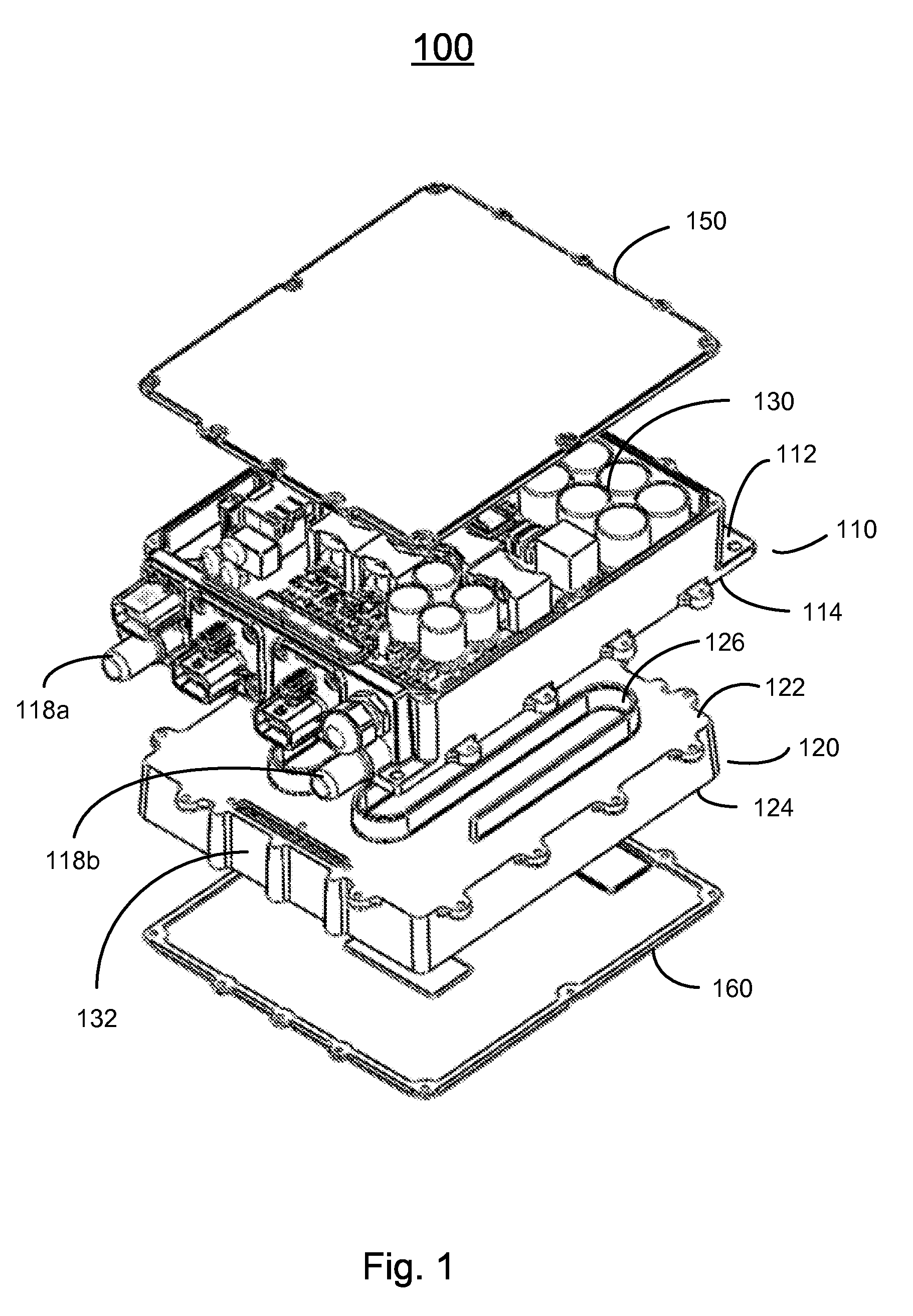
[0026] FIG. 1 shows an exploded perspective view of an electrical device, such as a battery charging system, that includes a cooling system, according to one embodiment of the present invention;
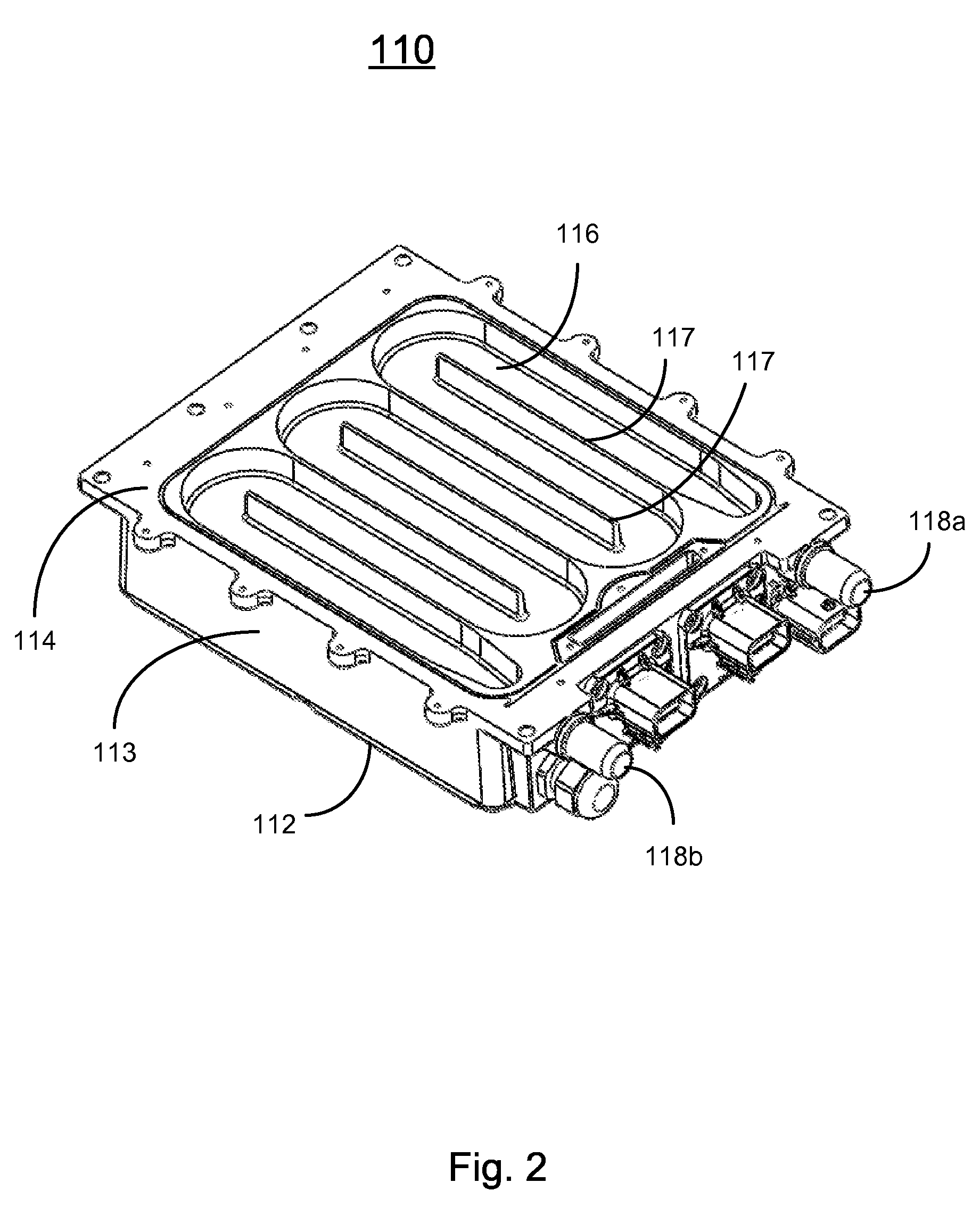
[0027] FIG. 2 shows a perspective view of a first cooling plate in the battery charging system shown in FIG. 1, according to one embodiment of the present invention;
[0028] FIG. 3 shows a perspective view of a second cooling plate in the battery charging system shown in FIG. 1, according to one embodiment of the present invention;
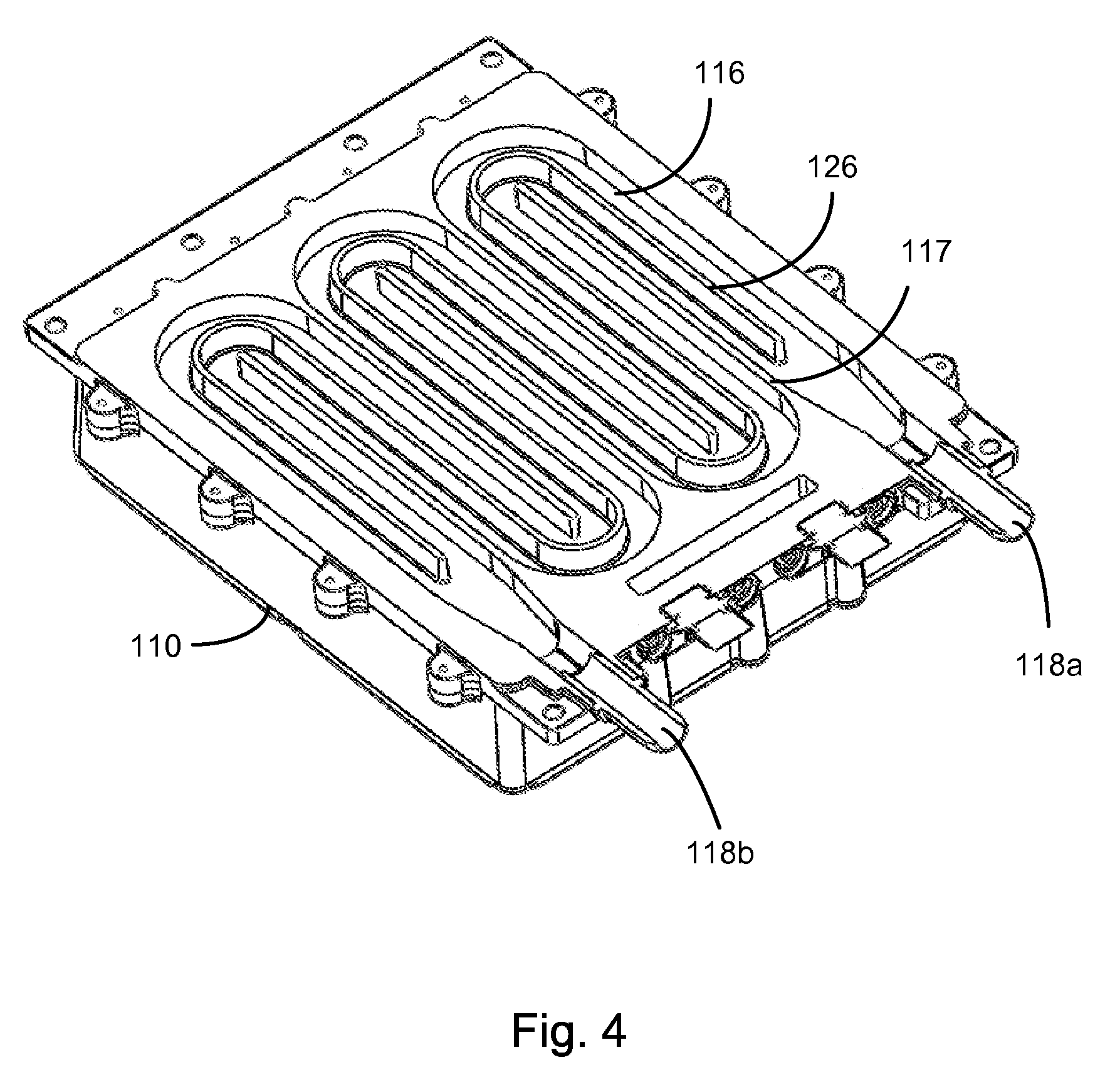
[0029] FIG. 4 shows a cutaway perspective view when coupling the first cooling plate to the second cooling plate of the cooling system in the battery charging system shown in FIG. 1, according to one embodiment of the present invention;
[0030] FIG. 5 shows a perspective view of the battery charging system shown in FIG. 1 as assembled;
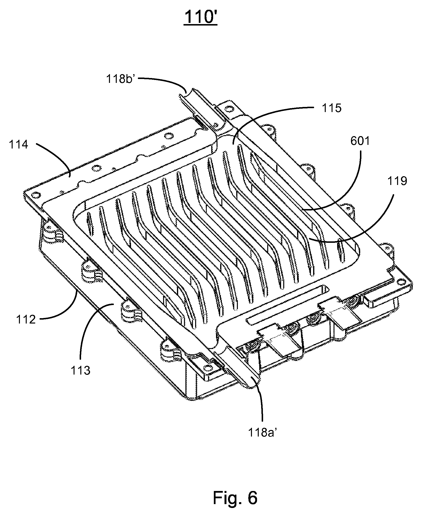
[0031] FIG. 6 shows a cutaway perspective view when coupling the first cooling plate to the second cooling plate of the cooling system in the battery charging system shown in FIG. 1, according to another embodiment of the present invention;
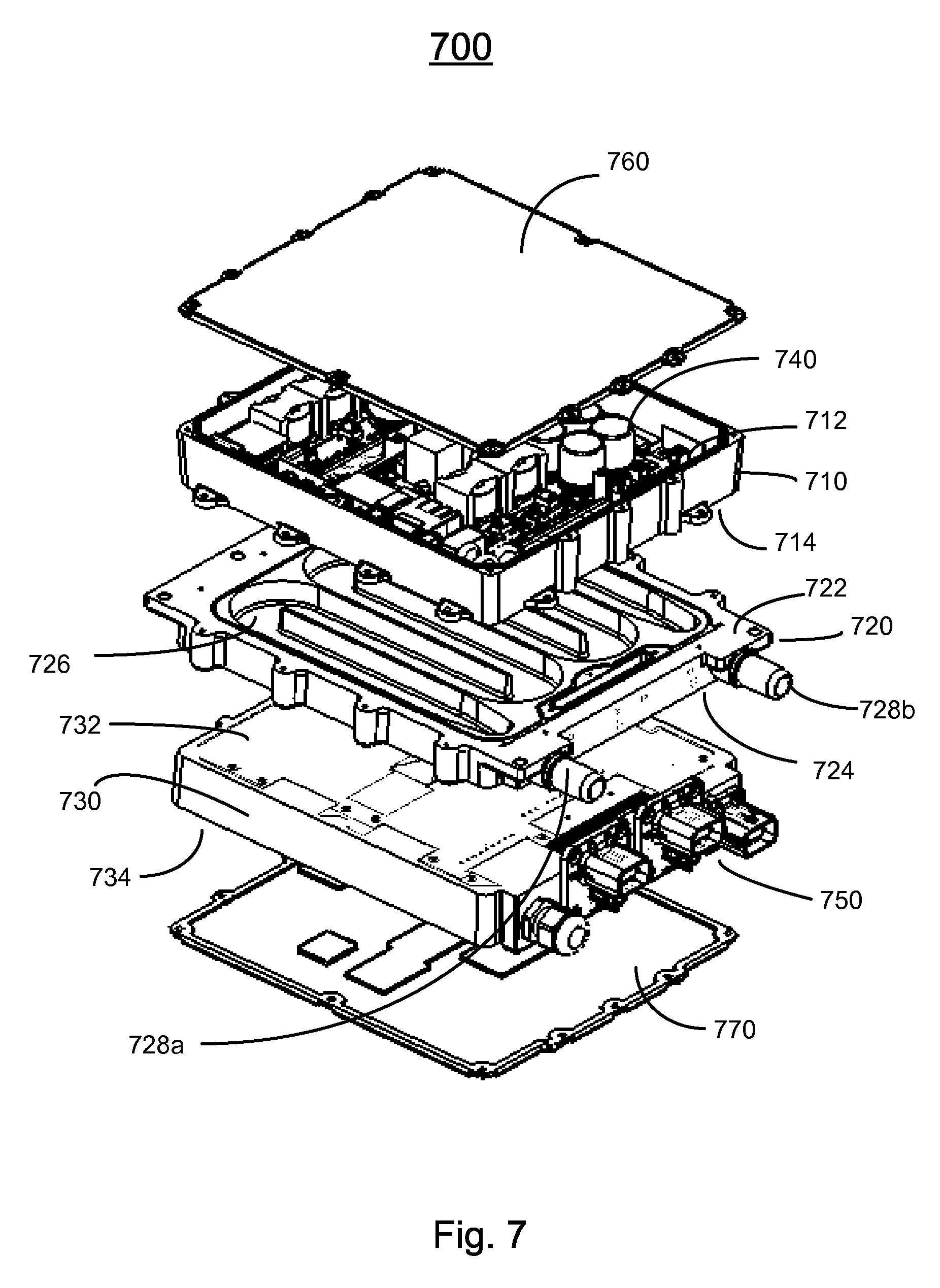
[0032] FIG. 7 shows an exploded perspective view of an electrical device, such as a battery charging system, that includes a cooling system, according to another embodiment of the present invention; and
[0033] FIG. 8 shows a perspective view of the battery charging system shown in FIG. 7 as assembled.
DETAILED DESCRIPTION OF THE INVENTION
[0034] The present invention will now be described more fully hereinafter with reference to the accompanying drawings, in which exemplary embodiments of the invention are shown. This invention may, however, be embodied in many different forms and should not be construed as limited to the embodiments set forth herein. Rather, these embodiments are provided so that this disclosure will be thorough and complete, and will fully convey the scope of the invention to those skilled in the art. Like reference numerals refer to like elements throughout.
[0035] It will be understood that when an element is referred to as being "on" another element, it can be directly on the other element or intervening elements may be present therebetween. In contrast, when an element is referred to as being "directly on" another element, there are no intervening elements present. As used herein, the term "and/or" includes any and all combinations of one or more of the associated listed items.
[0036] It will be understood that, although the terms first, second, third, etc. may be used herein to describe various elements, components, regions, layers and/or sections, these elements, components, regions, layers and/or sections should not be limited by these terms. These terms are only used to distinguish one element, component, region, layer or section from another element, component, region, layer or section. Thus, a first element, component, region, layer or section discussed below could be termed a second element, component, region, layer or section without departing from the teachings of the present invention.
[0037] The terminology used herein is for the purpose of describing particular embodiments only and is not intended to be limiting of the invention. As used herein, the singular forms "a", "an" and "the" are intended to include the plural forms as well, unless the context clearly indicates otherwise. It will be further understood that the terms "comprises" and/or "comprising," or "includes" and/or "including" or "has" and/or "having" when used herein, specify the presence of stated features, regions, integers, steps, operations, elements, and/or components, but do not preclude the presence or addition of one or more other features, regions, integers, steps, operations, elements, components, and/or groups thereof.
[0038] Furthermore, relative terms, such as "lower" or "bottom", "upper" or "top," and "front" or "back" may be used herein to describe one element's relationship to another element as illustrated in the figures. It will be understood that relative terms are intended to encompass different orientations of the device in addition to the orientation depicted in the figures. For example, if the device in one of the figures is turned over, elements described as being on the "lower" side of other elements would then be oriented on "upper" sides of the other elements. The exemplary term "lower", can therefore, encompasses both an orientation of "lower" and "upper," depending of the particular orientation of the figure. Similarly, if the device in one of the figures is turned over, elements described as "below" or "beneath" other elements would then be oriented "above" the other elements. The exemplary terms "below" or "beneath" can, therefore, encompass both an orientation of above and below.
[0039] Unless otherwise defined, all terms (including technical and scientific terms) used herein have the same meaning as commonly understood by one of ordinary skill in the art to which this invention belongs. It will be further understood that terms, such as those defined in commonly used dictionaries, should be interpreted as having a meaning that is consistent with their meaning in the context of the relevant art and the present disclosure, and will not be interpreted in an idealized or overly formal sense unless expressly so defined herein.
[0040] As used herein, "around", "about" or "approximately" shall generally mean within 20 percent, preferably within 10 percent, and more preferably within 5 percent of a given value or range. Numerical quantities given herein are approximate, meaning that the term "around", "about" or "approximately" can be inferred if not expressly stated.
[0041] As used herein, the term "plurality" means a number greater than one.
[0042] The description will be made as to the embodiments of the present invention in conjunction with the accompanying drawings in FIGS. 1-8. In accordance with the purposes of this invention, as embodied and broadly described herein, this invention, in one aspect, relates to a cooling system useable for an electrical device, such as a battery charging system.
[0043] FIG. 1 shows an exploded perspective view of a battery charging system 100 that includes a cooling system, according to one embodiment of the present invention. As shown in FIG. 1, the cooling system in the exemplary embodiment includes a first cooling plate 110 and a second cooling plate 120. Referring to FIGS. 1, 2 and 4 and particularly to FIG. 2, the first cooling plate 110 has a first surface 112, an opposite, second surface 114, a body portion 113 defined between the first surface 112 and the second surface 114, a plurality of fins 117 protruded from the bottom of the base of the body portion 113, so a concave channel 116 recessed from the second surface 114 and formed in the body portion for a cooling fluid to flow therethrough, an inlet 118a and an outlet 118b in flow communications with the channel 116 for the cooling fluid to enter and exit the channel 116, respectively. The inlet 118a is engaged with one end of the channel 116 and the outlet 118b is engaged with the other end of the channel 116. The inlet 118a and the outlet 118b are spatially separated by a distance. The channel 116 is serpentinely formed to define a zig-zag flow path of the cooling fluid flowing from the inlet 118a to the outlet 118b through the channel 116, where the zig-zag flow path has a path length substantially greater than the distance between the inlet 118a and the outlet 118b.
[0044] Referring to FIGS. 1, 3 and 4 and particularly to FIG. 3, the second cooling plate 120 has a first surface 122 and an opposite, second surface 124. The second cooling plate 120 has a fin 126 serpentinely protruding from the first surface 122 thereof.
[0045] The second surface 114 of the first cooling plate 110 is adapted for mating with the first surface 122 of the second cooling plate 120 such that as assembled, the first cooling plate 110 and the second cooling plate 120 is fastened together to form a sealed enclosure between the second surface 114 of the first cooling plate 110 and the first surface 122 of the second cooling plate 120 enclosing the channel 116. FIG. 4 shows a cutaway perspective view when coupling the first cooling plate 110 to the second cooling plate 120 of the cooling system 100 in the battery charging system shown in FIG. 1, according to one embodiment of the present invention. From the cutaway perspective view as shown in FIG. 4, when coupling the first cooling plate 110 to the second cooling plate 120, the fin 126 protruding from the first surface 122 of the second cooling plate 120 is placed in the channel 116 formed in the first cooling plate 110.
[0046] In an alternative embodiment (not shown), the first surface of the second cooling plate is substantially flat, while the first cooling plate 110 have a plurality of fins 117 serpentinely protruding in the channel 116 thereof.
[0047] As shown in FIG. 1, the battery charging system 100 includes a first power converter 130 and a second power converter 132, mounted on the first surface 112 of the first cooling plate 110 and the second surface 124 of the second cooling plate 120, respectively. In one embodiment, each of the first power converter 130 and the second power converter 132 is a high frequency power converter and outputs approximately 3.3 kW power. The first power converter 130 and the second power converter 132 may be connected to each other in series or in parallel to produce a total power of approximately 6.6 kW. The battery charging system 100 also includes a first cover plate 150 for enclosing the first power converter 130, and a second cover plate 160 for enclosing the second power converter 132.
[0048] FIG. 5 shows a perspective view of the assembled battery charging system 100. In operation, a cooling fluid flowing through the channel 116 carries away the heat generated by the first power converter 130 and the second power converter 132. Because the cooling system is sandwiched between the first power converter 130 and the second power converter 132, the battery charging system 100 is compact and the cooling is efficient.
[0049] FIG. 6 shows a cutaway perspective view when coupling the first cooling plate to the second cooling plate of the cooling system in the battery charging system shown in FIG. 1, according to another embodiment of the present invention. In this embodiment, the first cooling plate 110' has a cavity 115 recessed from the second surface 114 and formed in the body portion 113 thereof. A plurality of first parallel fins 601 is protruded from a bottom of the cavity 115. The second cooling plate (not shown) also has a plurality of second parallel fins protruding from the second surface 124 thereof. When the first cooling plate 110' and the second cooling plate are coupled together, the plurality of the second parallel fins are placed between the plurality of the first parallel fins 601 to form a plurality of channels 119 therebetween for a cooling fluid to flow therethrough. The first cooling plate 110' also has an inlet 118a' and an outlet 118b' in flow communications with the plurality of channels 119 for the cooling fluid to enter and exit the plurality of channels 119, respectively. The inlet 118a' and the outlet 118b' are spatially separated by a distance. In the example, the inlet 118a' and the outlet 118b' are positioned at two diagonal corners of the cavity 115.
[0050] Each of the plurality of channels 119 defines a respective flow path of the cooling fluid flowing from the inlet 118a' to the outlet 118b' through the corresponding channel, where the respective flow path has a path length substantially greater than the distance between the inlet 118a' and the outlet 118b'.
[0051] In this embodiment, the cooling fluid flows the plurality of channels 119 in the same direction, which reduces the pressure drop of the cooling fluid from the inlet 118a' to the outlet 118b'.
[0052] In an alternative embodiment, the second surface of the second cooling plate is substantially flat. So a plurality of channels is formed between the plurality of the first parallel fins 601 for a cooling fluid to flow therethrough.
[0053] FIG. 7 shows an exploded perspective view of a battery charging system 700 that includes a cooling system, according to another embodiment of the present invention. The battery charging system 700 includes a first cooling plate 710, a second cooling plate 720, and a third cooling plate 730. The first cooling plate has a first surface 712 and an opposite, second surface 714. The second cooling plate has a first surface 722 and an opposite, second surface 724. The third cooling plate has a first surface 732 and an opposite, second surface 734. The battery charging system 700 further includes a first power converter 740 mounted on the first surface 712 of the first cooling plate 710, and a second power converter 750 mounted on the second surface 734 of the third cooling plate 730.
[0054] In one embodiment, each of the first power converter 740 and the second power converter 750 is a high frequency power converter and outputs approximately 3.3 kW power. The first power converter 740 and the second power converter 750 may be connected to each other in series or in parallel to produce a total power of approximately 6.6 kW. The battery charging system 700 further includes a first cover 760 for enclosing the first power converter 740, and a second cover 770 for enclosing the second power converter 750.
[0055] The second cooling plate 720 is sandwiched between the first cooling plate 710 and the third cooling plate 730, and has a concave channel 726 formed on the first surface 722 thereof for a cooling fluid to flow therethrough. The first surface 722 of the second cooling plate 720 is adapted for mating with the second surface 714 of the first cooling plate 710 such that the first cooling plate 710 and the second cooling plate 720 can be fastened together to form a sealed enclosure between the second surface 714 of the first cooling plate 710 and the first surface 722 of the second cooling plate 720 enclosing the channel 726. The second cooling plate 720 further has an inlet 728a and an outlet 728b in flow communication with the channel 726 for the cooling fluid to enter and exit the channel 726, respectively. The channel 726 has a zig-zag contour covering a majority area of the first surface 722 of the second cooling plate 720. Each of the second surface 724 of the second cooling plate 720 and the first surface 732 of the third cooling plate 730 is substantially flat so that, when the second cooling plate 720 and the third cooling plate 730 are fastened together, the third cooling plate 730 is in good thermal contact with the second cooling plate 720.
[0056] In other embodiment, the second surface 724 can also have a concave channel for a cooling fluid to flow therethrough.
[0057] FIG. 8 shows a perspective view of the battery charging system 700 when assembled. The first cooling plate 710, the second cooling plate 720, and the third cooling plate 730 can be fastened together using screws, bolts, or other fastening means. In operation, a cooling fluid that flows through the channel 726 in the second cooling plate 720 carries away the heat generated by the first power converter 740 and the second power converter 750. Because the cooling system is sandwiched between the first power converter 740 and the second power converter 750, the battery charging system 700 is compact and the cooling is efficient.
[0058] Generally, the present invention relates to a cooling system that includes a cooling plate having a first surface and an opposite, second surface, a body portion defined between the first surface and the second surface, at least one channel formed in the body portion for a cooling fluid to flow therethrough, an inlet and an outlet in flow communications with the at least one channel for the cooling fluid to enter and exit the at least one channel, respectively. The inlet and the outlet are spatially separated by a distance. The at least one channel defines a flow path of the cooling fluid flowing from the inlet to the outlet through the at least one channel. The flow path has a path length substantially greater than the distance between the inlet and the outlet. The at least one channel can be formed serpentinely to define a zig-zag flow path.
[0059] The cooling system may further have a first plate having a first surface and an opposite, second surface, attached to the cooling plate such that the second surface of the first plate is substantially in contact with the first surface of the cooling plate. Additionally, the cooling system may also have a second plate having a first surface and an opposite, second surface, attached to the cooling plate such that the first surface of the second plate is substantially in contact with the second surface of the cooling plate.
[0060] Although the cooling system in its various embodiments is described above in the context of a battery charging system, it is understood that the cooling system can be used for other electrical systems that generate a significant amount of heat. The cooling system may be sandwiched between two modules of an electrical system, each module comprising one or more electrical components, such as switches, inductors, or capacitors. The electrical components may be mounted on, for example and without limitation, a printed circuit board (PCB). In other embodiment, there can be more than one cooling system, and one of them been sandwiched between two modules of an electrical system.
[0061] In one aspect of the present invention, an electrical device such as a battery charging system includes the cooling system as disclosed above.
[0062] In one embodiment, the electrical device also includes a first plate having a first surface and an opposite, second surface, attached to the cooling plate such that the second surface of the first plate is substantially in contact with the cooling system, where the first surface of the first plate is adapted for mounting at least one first electrical component thereon. The electrical device may further have a second plate having a first surface and an opposite, second surface, attached to the cooling plate such that the first surface of the second plate is substantially in contact with the cooling system, where the second surface of the second plate is adapted for mounting at least one second electrical component thereon. For example, the at least one first electrical component comprises a first power converter, while the at least one second electrical component comprises a second power converter
[0063] In another embodiment, the electrical device may have at least one first electrical component and at least one second electrical component, positioned such that the cooling system is sandwiched between the at least one first electrical component and the at least one second electrical component, where the at least one first electrical component and the at least one second electrical component are electrically connected to each other in series or in parallel.
[0064] The foregoing description of the exemplary embodiments of the invention has been presented only for the purposes of illustration and description and is not intended to be exhaustive or to limit the invention to the precise forms disclosed. Many modifications and variations are possible in light of the above teaching.
[0065] The embodiments were chosen and described in order to explain the principles of the invention and their practical application so as to activate others skilled in the art to utilize the invention and various embodiments and with various modifications as are suited to the particular use contemplated. Alternative embodiments will become apparent to those skilled in the art to which the present invention pertains without departing from its spirit and scope. Accordingly, the scope of the present invention is defined by the appended claims rather than the foregoing description and the exemplary embodiments described therein.
* * * * *
D00000
D00001
D00002
D00003
D00004
D00005
D00006
D00007
D00008
XML
uspto.report is an independent third-party trademark research tool that is not affiliated, endorsed, or sponsored by the United States Patent and Trademark Office (USPTO) or any other governmental organization. The information provided by uspto.report is based on publicly available data at the time of writing and is intended for informational purposes only.
While we strive to provide accurate and up-to-date information, we do not guarantee the accuracy, completeness, reliability, or suitability of the information displayed on this site. The use of this site is at your own risk. Any reliance you place on such information is therefore strictly at your own risk.
All official trademark data, including owner information, should be verified by visiting the official USPTO website at www.uspto.gov. This site is not intended to replace professional legal advice and should not be used as a substitute for consulting with a legal professional who is knowledgeable about trademark law.