Cooling Device
Honmura; Osamu ; et al.
U.S. patent application number 13/405424 was filed with the patent office on 2012-12-27 for cooling device. This patent application is currently assigned to TOSHIBA HOME TECHNOLOGY CORPORATION. Invention is credited to Osamu Honmura, Nobuo Ito, Nobuyuki Kojima, Naoto Sakuma.
| Application Number | 20120325440 13/405424 |
| Document ID | / |
| Family ID | 47360722 |
| Filed Date | 2012-12-27 |


View All Diagrams
| United States Patent Application | 20120325440 |
| Kind Code | A1 |
| Honmura; Osamu ; et al. | December 27, 2012 |
COOLING DEVICE
Abstract
There is provided a cooling device not affected by gravity by exerting a strong capillary attraction to be hard to deteriorate in transportation function. Unidirectionally-aligned copper fiber assembly 8 is mounted, by a sintering process, on an inner wall of a heat pipe 3 along the longitudinal direction of the heat pipe 3. Therefore, by a strong capillary attraction caused by fine copper fiber assembly 8, purified water can be transported without being affected by gravity. A flow volume just enough for the purified water to be prevented from drying out by its evaporation can be maintained, thus making it hard for a function in the transportation of the purified water to be deactivated. Further, the unidirectionally-aligned copper fiber assembly 8 is mounted along the longitudinal direction of heat pipe 3 and hence the purified water smoothly flows in the longitudinal direction of heat pipe 3.
| Inventors: | Honmura; Osamu; (Kamo, JP) ; Kojima; Nobuyuki; (Kamo-shi, JP) ; Sakuma; Naoto; (Kamo-shi, JP) ; Ito; Nobuo; (Kamo-shi, JP) |
| Assignee: | TOSHIBA HOME TECHNOLOGY
CORPORATION Kamo JP |
| Family ID: | 47360722 |
| Appl. No.: | 13/405424 |
| Filed: | February 27, 2012 |
| Current U.S. Class: | 165/104.26 |
| Current CPC Class: | F28F 21/084 20130101; F28D 15/0275 20130101; F28F 2255/18 20130101; F28D 15/046 20130101 |
| Class at Publication: | 165/104.26 |
| International Class: | F28D 15/04 20060101 F28D015/04 |
Foreign Application Data
| Date | Code | Application Number |
|---|---|---|
| Jun 27, 2011 | JP | 2011-141551 |
| Oct 19, 2011 | JP | 2011-229706 |
| Jan 13, 2012 | JP | 2012-005509 |
Claims
1. A cooling device comprising: a pipe; and fine fibers mounted inside said pipe for causing capillary attraction.
2. The cooling device according to claim 1, wherein a fiber assembly is formed from said fibers aligned in an unidirectional direction, said fiber assembly being mounted on an inner wall of said pipe by a sintering process along a longitudinal direction of said pipe.
3. The cooling device according to claim 1, further comprising grooves formed in an inner wall of said pipe, wherein a fiber assembly formed from said fibers is mounted so as to be attached closely to insides of said grooves.
4. The cooling device according to claim 3, wherein said fiber assembly formed from said fibers aligned in a unidirectional direction is mounted by a sintering process along a longitudinal direction of said pipe.
5. The cooling device according to claim 1, further comprising grooves formed in an inner wall of said pipe, wherein a tube produced by weaving said fibers into a mesh structure is mounted on insides of said grooves.
6. The cooling device according to claim 1, further comprising grooves formed in an inner wall of said pipe, wherein said fibers are mounted on insides of said grooves.
7. The cooling device according to claim 6, wherein materials of said pipe and said fibers are copper.
8. The cooling device according to claim 6, wherein a diameter of said fibers is 20 .mu.m or more and is smaller than a width of said groove.
9. The cooling device according to claim 1, further comprising: grooves formed in an inner wall of said pipe; and a sheet produced by sintering said fibers, wherein said sheet is attached closely to protrusions of said grooves to sinter said fibers and said grooves together.
10. The cooling device according to claim 1, further comprising: grooves formed in an inner wall of said pipe; and an unwoven fabric produced by laying linear fibers and web fibers on top of another both of which are metallic and act as said fibers, said unwoven fabric being mounted so as to be attached closely to protrusions of said grooves.
11. The cooling device according to claim 1, further comprising: grooves formed in an inner wall of said pipe; and a sheet produced by joining linear fibers and web fibers together by sintering an unwoven fabric produced by laying said linear fibers and said web fibers on top of another both of which are metallic and act as said fibers, said sheet being mounted so as to be attached closely to protrusions of said grooves.
12. The cooling device according to claim 7, wherein a diameter of said fibers is 20 .mu.m or more and is smaller than a width of said groove.
Description
BACKGROUND OF THE INVENTION
[0001] 1. Field of the Invention
[0002] The present invention relates to a cooling device which is suitable for cooling a heat source and enables a large amount of heat transportation despite its compact size.
[0003] 2. Description of the Related Art
[0004] Heretofore, there has been known a cooling device utilizing a capillary attraction effected by grooves and copper powders as a result of forming the grooves on an inner wall of a pipe and sintering the copper powders on the inner wall of the pipe to carry a working fluid condensed in a heat dissipating section to a heat receiving section (e.g., Japanese unexamined patent application publication No. 2006-284020).
[0005] The conventional structure, however, functions poorly in carrying a working fluid from the heat dissipating section to the heat receiving section. In other words, the capillary attraction is weak in a cooling device formed with the grooves on the inner wall of the pipe, halting, in some cases, a function in the transportation of the working fluid under the influence of gravity depending on the installation attitude of a heat dissipating unit. Further, in a device formed with copper powders on the inner wall of the pipe by a sintering process, a flow volume of the working fluid is insufficient and therefore the function in the transportation of the working fluid is prone to deteriorate in some cases. Hence, there is no other choice than to increase an amount of the copper powders to obtain a sufficient flow volume of the working fluid, incurring such a drawback as growths in size and weight of device.
SUMMARY OF THE INVENTION
[0006] With a view to the problems described above, it is an object of the present invention to provide a cooling device in which a capillary attraction is so strong as to be unaffected by gravity, and a function in the transportation of a working fluid is hard to deteriorate by securing an enough flow volume of the working fluid.
Means for Solving the Problem
[0007] A first aspect of the present invention is a cooling device in which a working liquid accumulates at one end of a pipe by steam condensation, while the working liquid evaporates at the other end of the pipe. By a strong capillary attraction due to fine fibers, the working fluid can be transported without being affected by gravity and a flow volume just enough for the working fluid to be prevented from drying out by its evaporation can be maintained, making it hard for the function in the transportation of the working fluid required for the cooling device to be deactivated.
[0008] A second aspect of the present invention is a cooling device in which a fiber body comprising unidirectionally-aligned fibers is mounted along the longitudinal direction of the pipe and hence the working fluid smoothly flows in the longitudinal direction of the pipe, making it further hard for the function in the transportation of the working fluid to be deactivated. Furthermore, the fiber body is mounted on an inner wall of the pipe by sintering to maintain the thermal conductivity between the pipe and the fiber body at a favorable condition, permitting the thermal resistance of the pipe to become excellent.
[0009] A third aspect of the present invention is a cooling device in which the working fluid can be infallibly transported by a strong capillary attraction exerted by the fine fibers in addition to the capillary attraction of the grooves formed in the inner wall of the pipe without being affected by gravity. Further, the flow volume just enough for the working fluid to be prevented from drying out by its evaporation can be sufficiently maintained, making it further hard for the function in the transportation of the working fluid required for the cooling device to be deactivated. Furthermore, by covering the openings of the grooves with the fibers, the capillary attraction is dramatically improved, permitting enhancing the performance of the cooling device.
[0010] A fourth aspect of the present invention is a cooling device in which the fiber body comprising the unidirectionally-aligned fibers is mounted along the longitudinal direction of the pipe and hence the working fluid smoothly flows in the longitudinal direction of the pipe, making it furthermore hard for the function in the transportation of the working fluid to be deactivated. Further, the fiber body is mounted on the grooves formed in the inner wall of the pipe by a sintering process to maintain the thermal conductivity between the pipe and the fiber body at a favorable condition, permitting the thermal resistance of the pipe to become excellent.
[0011] A fifth aspect of the present invention is a cooling device in which the working fluid can be infallibly transported by a strong capillary attraction exerted by the fine fibers in addition to the capillary attraction of the grooves formed in the inner wall of the pipe without being affected by gravity. Further, the flow volume just enough for the working fluid to be prevented from drying out by its evaporation can be maintained, making it further hard for the function in the transportation of the working fluid required for the cooling device to be deactivated. Further, by weaving fibers in a mesh structure, the fibers can be uniformly mounted in a given position inside the pipe. Besides, since a tube is formed by the fibers, the mounting workability on the pipe becomes favorable, leading to low cost. Furthermore, by covering the openings of the grooves with the fibers, the capillary attraction is spectacularly improved, permitting the performance of the cooling device to be improved.
[0012] A sixth aspect of the present invention is a cooling device in which the working fluid can be infallibly transported by a strong capillary attraction exerted by the fine fibers in addition to the capillary attraction of the grooves formed in the inner wall of the pipe without being affected by gravity. Further, the flow volume just enough for the working fluid to be prevented from drying out by its evaporation can be sufficiently maintained, making it further hard for the function in the transportation of the working fluid required for the cooling device to be deactivated. Furthermore, by covering the openings of the grooves with the fibers, the capillary attraction is spectacularly improved, permitting the performance of the cooling device to be improved.
[0013] A seventh aspect of the present invention is a cooling device in which the material of the pipe formed with the grooves and the material of the fibers are both copper to maximize the capillary attraction, permitting the performance of the cooling device to be further improved.
[0014] An eighth aspect of the present invention is a cooling device in which by employing the fibers with a diameter not less than 20 .mu.m, such a trouble with workability as breaking of the fibers can be avoided. Besides, when the diameter of the fiber is smaller than a width of the groove, a free exchange between a gas phase and a liquid phase becomes possible, permitting the performance of the cooling device to be further improved.
[0015] A ninth aspect of the present invention is a cooling device in which the working fluid can be infallibly transported by a strong capillary attraction exerted by the fine fibers in addition to the capillary attraction of the grooves formed in the inner wall of the pipe without being affected by gravity. Further, the flow volume just enough for the working fluid to be prevented from drying out by its evaporation can be maintained, making it further hard for the function in the transportation of the working fluid required for the cooling device to be deactivated. Furthermore, after the sheet with which the fibers have been sintered in advance is mounted in the pipe, the sheet is attached closely to the pipe to sinter the sheet and the protrusions of the grooves together, thereby permitting the capillary attraction to be maximally improved and the thick of the sheet to be reduced to the utmost extent. Moreover, by covering the openings of the grooves with the fibers, the capillary attraction is spectacularly improved, permitting the performance of the cooling device to be improved. Moreover, the fiber body is mounted on the grooves formed in the inner wall of the pipe by sintering to maintain the thermal conductivity between the pipe and the fiber body at a favorable condition, permitting the thermal resistance of the pipe to become excellent.
[0016] A tenth aspect of the present invention is a cooling device in which the working fluid can be infallibly transported by a strong capillary attraction exerted by the fine fibers in addition to the capillary attraction of the groove formed in the inner wall of the pipe without being affected by gravity. Further, the flow volume just enough for the working fluid to be prevented from drying out by its evaporation can be maintained, making it further hard for the function in the transportation of the working fluid required for the cooling device to be deactivated. Furthermore, by mounting an unwoven cloth, produced by laying linear fabrics and web fabrics on top of another, inside the pipe, a closely-attached condition between the unwoven cloth and the protrusions is excellent and besides the openings of the grooves are covered with the unwoven cloth with minute gaps. Therefore, the capillary attraction can be spectacularly improved to enable the performance of the cooling device to be improved and the pipe to be thinned due to the thin unwoven cloth. Moreover, by mounting the unwoven cloth on the grooves formed on the inside wall of the pipe by a sintering process, the thermal conductivity between the pipe and the unwoven cloth is maintained at a favorable condition, permitting the thermal resistance of the pipe to become excellent.
[0017] An eleventh aspect of the present invention is a cooling device in which the working fluid can be infallibly transported by a strong capillary attraction exerted by the fine fibers in addition to the capillary attraction of the groove formed in the inner wall of the pipe without being affected by gravity. Further, the flow volume just enough for the working fluid to be prevented from drying out by its evaporation can be maintained, making it further hard for the function in the transportation of the working fluid required for the cooling device to be deactivated. Furthermore, by mounting a sheet, produced by laying linear fabrics and web fabrics on top of another, inside the pipe, the sheet and the protrusions contact closely with each other and besides the openings of the grooves are covered with the sheet with minute gaps. Therefore, the capillary attraction can be spectacularly improved to enable the performance of the cooling device to be improved and the pipe to be thinned due to the thin sheet. Moreover, by mounting the sheet on the grooves formed on the inside wall of the pipe by a sintering process, the thermal conductivity between the pipe and the sheet is maintained at a favorable condition, permitting the thermal resistance of the pipe to become excellent.
[0018] According to the first aspect of the present invention, there can be provided the cooling device in which the capillary attraction is so strong as to be unaffected by gravity so that it is hard for the function in the transportation of the working fluid to deteriorate owing to the enough flow volume of the working fluid.
[0019] According to the second aspect of the present invention, the function in the transportation of the working fluid can become further hard to be deactivated and besides the thermal resistance of the pipe is caused to become excellent.
[0020] According to the third aspect of the present invention, there can be provided the cooling device in which the capillary attraction is so strong as to be unaffected by gravity so that it is hard for the function in the transportation of the working fluid to deteriorate owing to the enough flow volume of the working fluid. Further, the capillary attraction is spectacularly improved, permitting the performance of the cooling device to be improved.
[0021] According to the fourth aspect of the present invention, the function in the transportation of the working fluid can become further hard to be deactivated and besides the thermal resistance of the pipe is caused to become excellent.
[0022] According to the fifth aspect of the present invention, there can be provided the cooling device in which the capillary attraction is so strong as to be unaffected by gravity so that it is further hard for the function in the transportation of the working fluid to deteriorate owing to the enough flow volume of the working fluid. Further, there can be provided the cooling device with the favorable workability of the mounting on the pipe and low cost, and the capillary attraction is spectacularly improved, permitting the performance of the cooling device to be improved.
[0023] According to the sixth aspect of the present invention, there can be provided the cooling device in which the capillary attraction is so strong as to be unaffected by gravity so that it is further hard for the function in the transportation of the working fluid to deteriorate owing to the enough flow volume of the working fluid. Further, the capillary attraction is spectacularly improved, permitting the performance of the cooling device to be improved.
[0024] According to the seventh aspect of the present invention, the capillary attraction is maximized, permitting the performance of the cooling device to be further improved.
[0025] According to the eighth aspect of the present invention, a gas phase and a liquid phase can be freely exchanged therebetween, permitting the performance of the cooling device to be further improved.
[0026] According to the ninth aspect of the present invention, there can be provided the cooling device in which the capillary attraction is so strong as to be unaffected by gravity so that it is further hard for the function in the transportation of the working fluid to deteriorate owing to the enough flow volume of the working fluid. Further, the capillary attraction is maximally improved and the thick of the sheet is reduced to the utmost extent. Furthermore, the capillary attraction is spectacularly improved, permitting the performance of the cooling device to be improved and besides the thermal resistance of the pipe is caused to become excellent.
[0027] According to the tenth aspect of the present invention, there can be provided the cooling device in which the capillary attraction is so strong as to be unaffected by gravity so that it is further hard for the function in the transportation of the working fluid to deteriorate owing to the enough flow volume of the working fluid. Further, the capillary attraction is spectacularly improved, permitting the performance of the cooling device to be improved. Furthermore, the pipe can be thinned and besides the thermal resistance of the pipe is caused to become excellent.
[0028] According to the eleventh aspect of the present invention, there can be provided the cooling device in which the capillary attraction is so strong as to be unaffected by gravity so that it is further hard for the function in the transportation of the working fluid to deteriorate owing to the enough flow volume of the working fluid. Further, the capillary attraction is spectacularly improved, permitting the performance of the cooling device to be improved. Furthermore, the pipe can be thinned and besides the thermal resistance of the pipe is caused to become excellent.
BRIEF DESCRIPTION OF THE DRAWINGS
[0029] These objects and other objects and advantages of the present invention will become more apparent upon reading of the following detailed description and the accompanying drawings in which:
[0030] FIG. 1 is an outline perspective view of a heat sink unit acting as a cooling device common to each embodiment according to the present invention.
[0031] FIG. 2 is an outline perspective view of a heat sink unit acting as a cooling device shown from the other direction than FIG. 1.
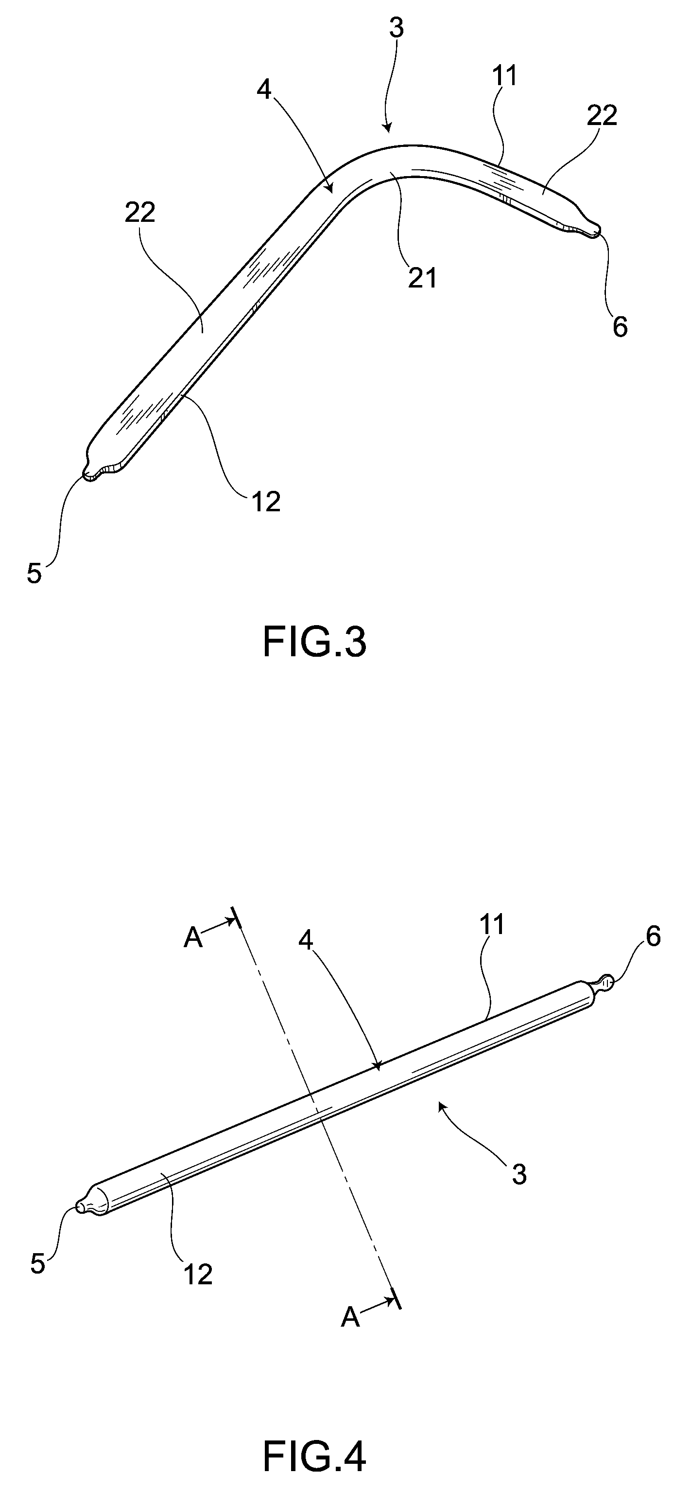
[0032] FIG. 3 is an outline perspective view of a single body of a heat pipe after applying a flattening process thereto, illustrating a heat sink unit acting as a cooling device common to each embodiment according to the present invention.
[0033] FIG. 4 is an outline perspective view of the single body of the heat pipe before being subjected to the flattening process, illustrating a heat sink unit acting as a cooling device common to each embodiment according to the present invention.
[0034] FIG. 5 is a cross-sectional view on an A-A line in FIG. 4, illustrating the first embodiment according to the present invention.
[0035] FIG. 6 is an outline view of randomly directed copper fibers, illustrating the first embodiment according to the present invention.
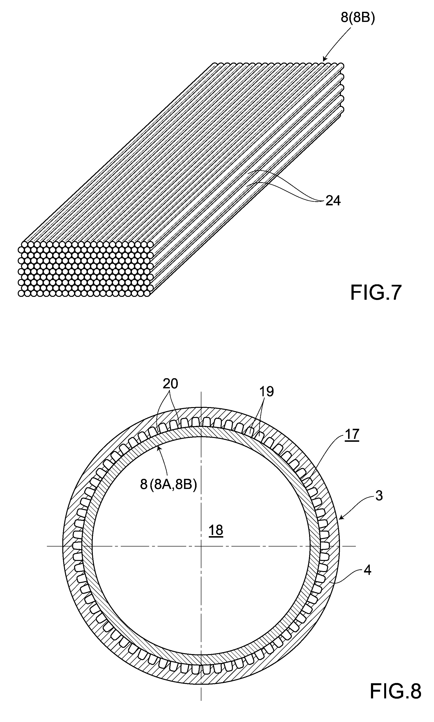
[0036] FIG. 7 is an outline view of unidirectionally-aligned copper fibers, illustrating the first embodiment according to the present invention.
[0037] FIG. 8 is a cross-sectional view on A-A line in FIG. 4 showing another example of a cooling device, illustrating the first embodiment according to the present invention.
[0038] FIG. 9 is a photograph of a partial cross-sectional view after mounting and sintering copper fibers, illustrating the first embodiment according to the present invention.
[0039] FIG. 10 is an enlarged photograph of FIG. 9, illustrating the first embodiment according to the present invention.
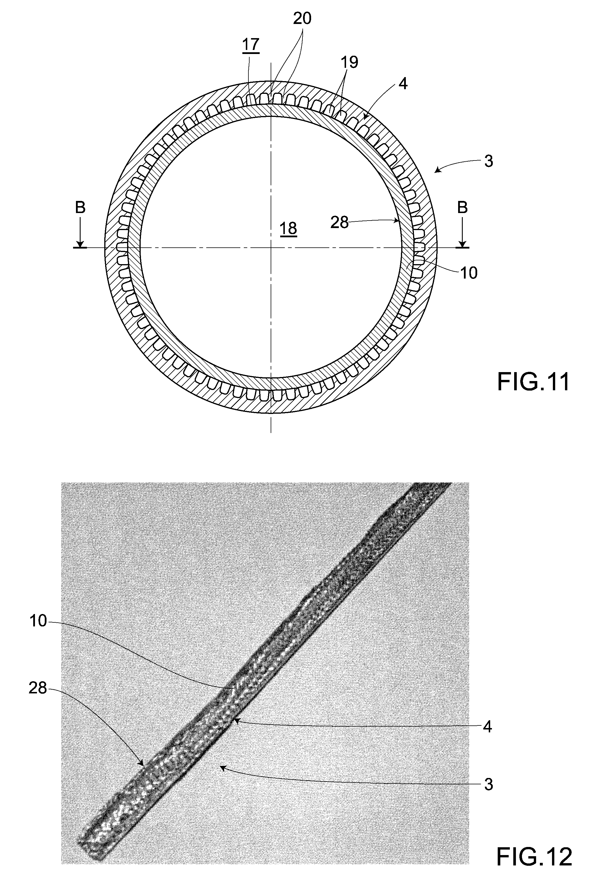
[0040] FIG. 11 is a cross-sectional view on an A-A line in FIG. 4, illustrating a second embodiment according to the present invention.
[0041] FIG. 12 is a photograph of an actual heat pipe along a B-B line in FIG. 11, illustrating the second embodiment according to the present invention.
[0042] FIG. 13 is an enlarged photograph of FIG. 12, illustrating the second embodiment according to the present invention.
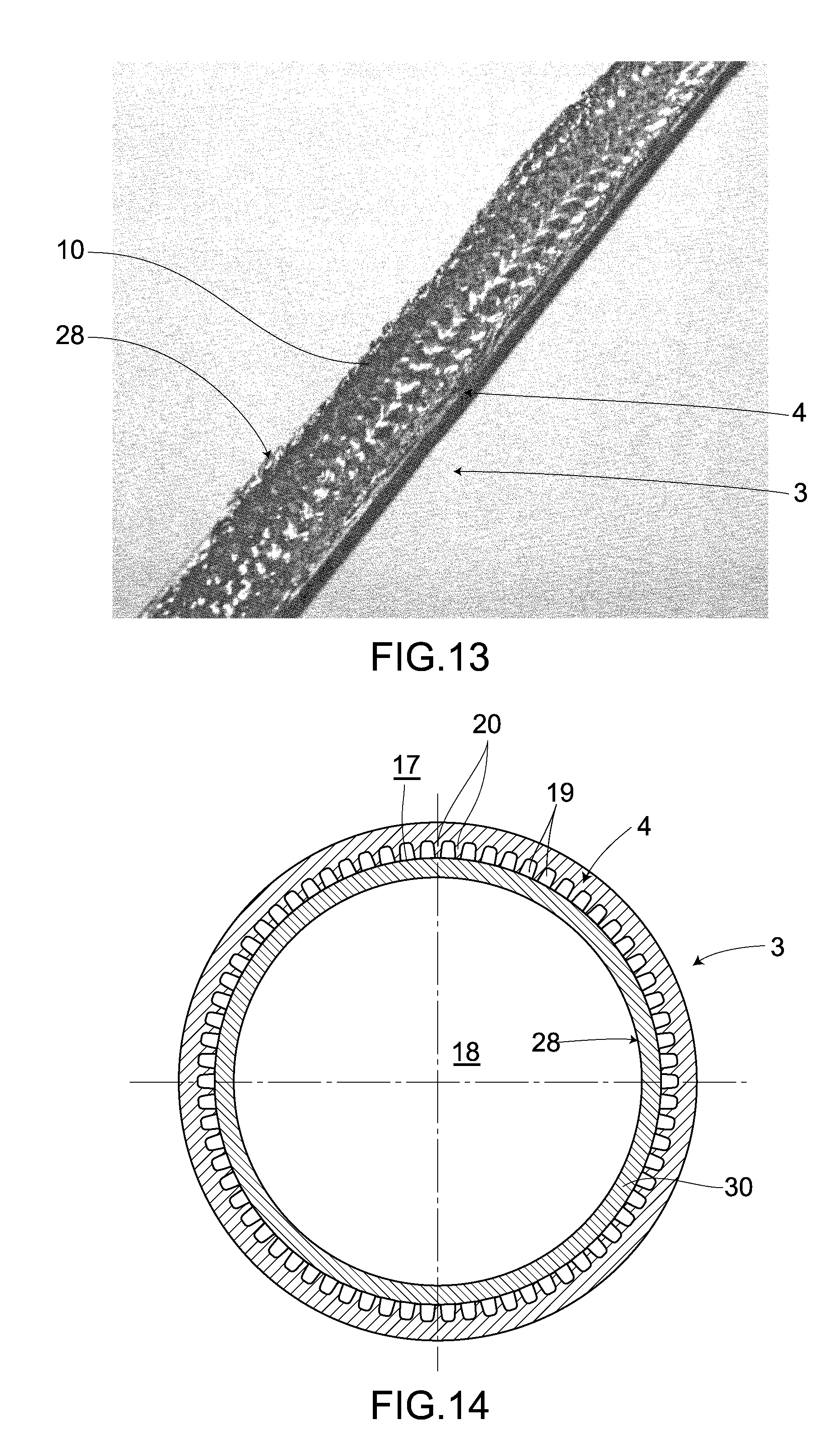
[0043] FIG. 14 is a cross-sectional view on an A-A line in FIG. 4, illustrating a third embodiment according to the present invention.
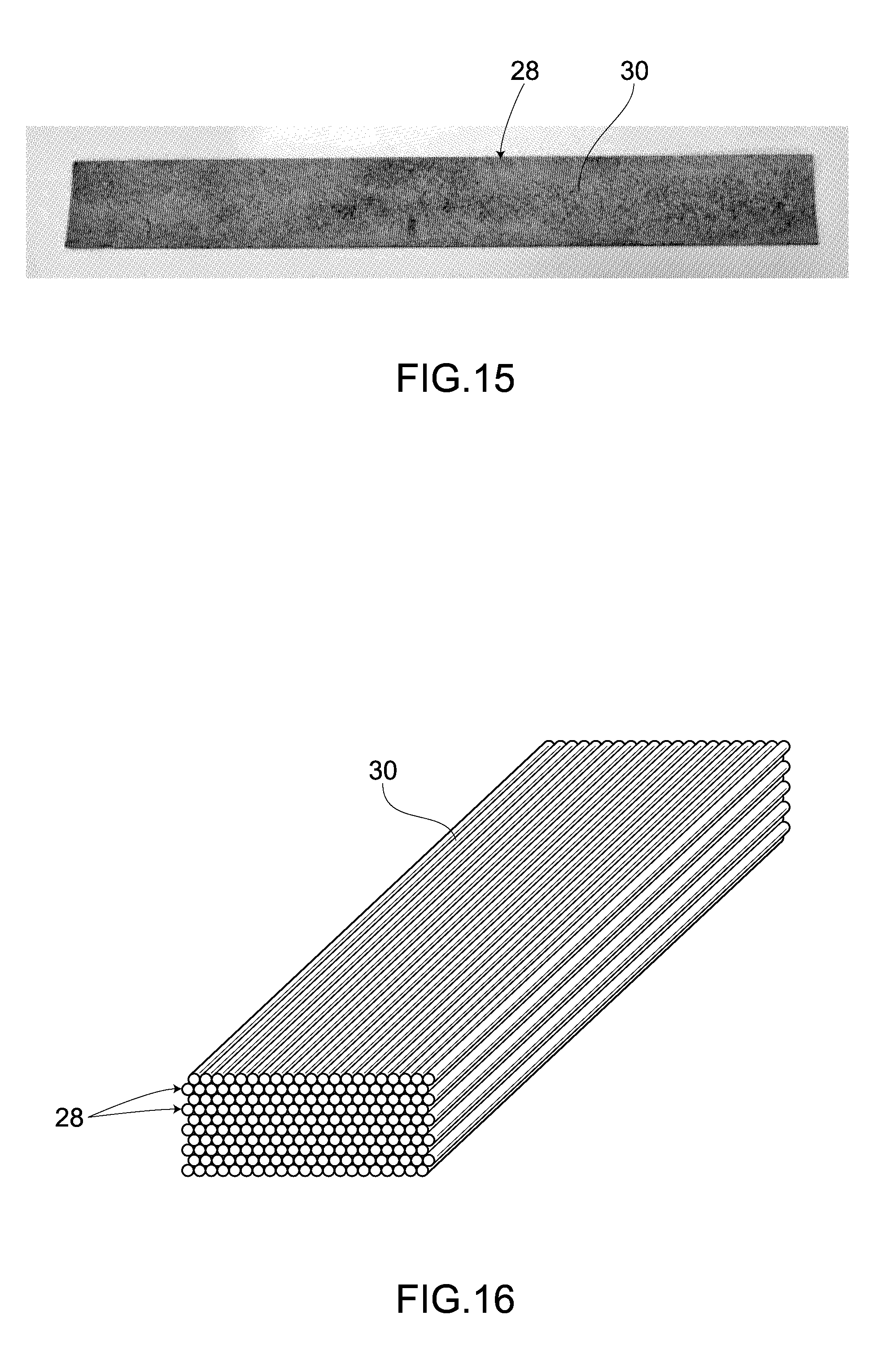
[0044] FIG. 15 is a photograph of an outline perspective view of the sheet comprising copper fibers, illustrating the third embodiment according to the present invention.
[0045] FIG. 16 is an outline perspective view of the copper fibers, illustrating the third embodiment according to the present invention.
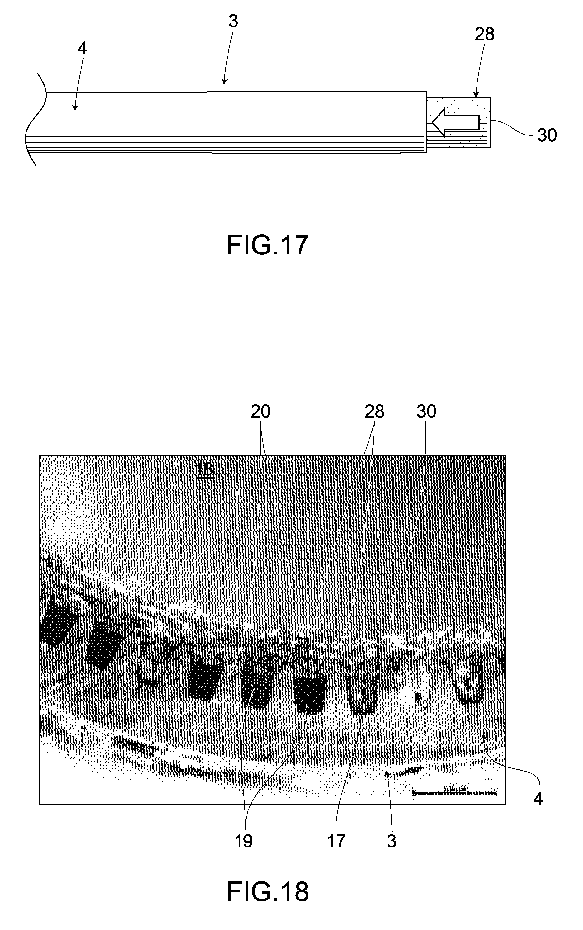
[0046] FIG. 17 is an outline view of a chief part in the process of mounting the sheet, illustrating the third embodiment according to the present invention.
[0047] FIG. 18 is a photograph of a cross section of a chief part in the heat pipe, illustrating the third embodiment according to the present invention.
[0048] FIG. 19 is a photograph of a cross section of the whole part in the heat pipe, illustrating the third embodiment according to the present invention.
[0049] FIG. 20 is a cross-sectional view on an A-A line in FIG. 4, illustrating the fourth embodiment according to the present invention.
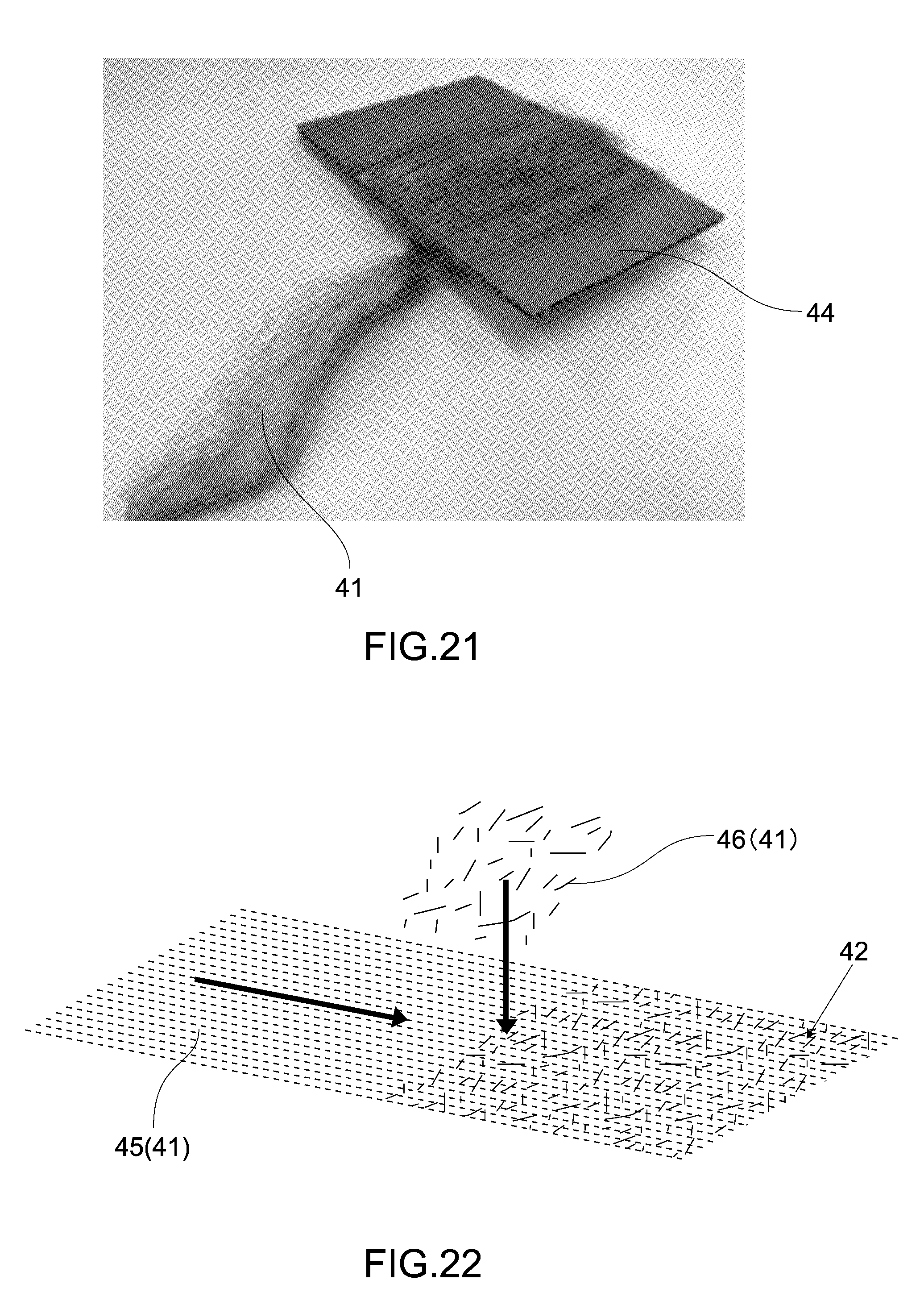
[0050] FIG. 21 is a photograph of metal fibers wound around a piece of cardboard, illustrating the fourth embodiment according to the present invention.
[0051] FIG. 22 is an explanation drawing showing manufacturing process of a nonwoven fabric, illustrating the fourth embodiment according to the present invention.
[0052] FIG. 23 is a photograph of a sintered sheet after sintering the nonwoven fabric, illustrating the fourth embodiment according to the present invention.
[0053] FIG. 24A is a partially enlarged photograph showing surface of a web fiber side of a sintered sheet, illustrating the fourth embodiment according to the present invention.
[0054] FIG. 24B is a partially enlarged photograph showing surface of a linear fiber side of a sintered sheet, illustrating the fourth embodiment according to the present invention.
[0055] FIG. 25 is an outline view of a chief part in a process of mounting the sintered sheet, illustrating the fourth embodiment according to the present invention.
[0056] FIG. 26 is a photograph of a cross section of a chief part in the heat pipe, illustrating the fourth embodiment according to the present invention.
[0057] FIG. 27 is a photograph of a cross section of the whole part in the heat pipe, illustrating the fourth embodiment according to the present invention.
[0058] FIG. 28 is a photograph of a cross section of the whole part in the heat pipe according to the conventional art by way of comparison with FIG. 19 and FIG. 27.
DETAILED DESCRIPTION OF PREFERRED EMBODIMENTS
[0059] Hereunder, preferred embodiments of a cooling device according to the present invention is described with a heat sink unit for cooling a CPU or the like acting as a main heat dissipating component of a personal computer taken as an example.
[0060] FIG. 1 and FIG. 2 show an overall structure of the heat sink unit, common to each embodiment, acting as a cooling device. In these figures, numeral symbol 1 denotes a copper heat receiving plate attached closely to the CPU (not shown), and numeral symbol 2 denotes heat dissipating fins made up by combining a plurality of metallic plates for partitioning and forming a plurality of air paths. The heat receiving plate 1 is coupled closely to a heat receiving section 11 formed at the other end of a heat pipe 3 acting as a pipe, while the heat dissipating fins 2 are coupled closely to a heat dissipating section 12 formed at one end of the heat pipe 3. An air stream from a blower module, not shown, passes through each air path in the heat dissipating section 12.
[0061] As shown in FIG. 3 and FIG. 4, the heat pipe 3 is formed preferably from a material for a metallic pipe such as copper or copper alloys which have high thermal conductivity. A hollow cylindrical container 4 acts as a main body of the heat pipe 3 and extends in its longitudinal direction. There are formed sealed portions 5, 6 which are sealed by an appropriate means such as Tig welding at both ends of the container 4, thus sealing up the container 4 into a vacuum state. Further, in a state, shown in FIG. 4, before flattening and bending the heat pipe 3, the whole of the heat pipe 3 is linear and is formed uniformly in outer shape and thickness over entire length in the axial direction except for the sealed portions 5, 6.
[0062] Now, when installing a heat sink unit including a heat pipe 3 in a low-profile electronic device such as a notebook-size personal computer, an installation space is limited inside the low-profile electronic device and therefore in a state, shown in FIG. 3, subsequent to the flattening and bending processes, a bent portion 21 is formed at an appropriate place of the container 4 as necessary and besides there is formed a flattened portion 22 which is produced by applying the flattening process to part of or the whole of the container 4. A surface of the container 4 formed with the flattened portion 22 is approximately flat. According to the present embodiment, the flattened portion 22 is formed in at least the heat receiving section 11 and heat dissipating section 12 of the heat pipe 3, and then the heat receiving plate 1 and the heat dissipating fins 2 are mounted on the flattened portion 22. Thus, a closely-attached condition between the heat receiving plate 1 and heat dissipating fins 2, and the heat pipe 3 is enhanced.
[0063] FIG. 5 to FIG. 10 show heat sink unit according to a first embodiment according to the present invention. Specifically, FIG. 5 shows a cross-sectional view orthogonal to the longitudinal direction of the heat pipe 3 shown in FIG. 4. In FIG. 5, the inner wall of the container 4, shown here, is formed into a smooth curved surface 16 without irregularities and the copper fiber assembly 8 acting as a fiber assembly with a wicked structure is hermetically housed inside the heat pipe 3 so as to be attached closely to the curved surface 16. The copper fiber assembly 8 is uniformly mounted without a break in mid-course from one end of the heat pipe 3 to the other end thereof. Then, inside the heat pipe 3, there are provided a first flow path 17 formed inside the copper fiber assembly 8 to transfer purified water (not shown), acting as a working fluid condensed in the heat dissipating section 12, toward the heat receiving section 11, and a second flow path 18 formed in a region surrounded by the copper fiber assembly 8 to transfer steam evaporated in the heat receiving section 11 toward the heat dissipating section 12.
[0064] Each of FIG. 6 and FIG. 7 shows an outer appearance of a single body of the copper fiber assembly 8. The copper fiber assembly 8A shown in FIG. 6 is formed so that copper wires 24 acting as a plurality of fibers with a diameter ranging from a few micrometers to several tens of micrometers are randomly entwined with one another, while the copper fiber assembly 8B shown in FIG. 7 is formed so that copper wires 24 acting as a plurality of comparatively longer fibers, with a diameter range from a few micrometers to several tens of micrometers, than those of the copper fiber assembly 8A are unidirectionally aligned in layers and are entwined with one another. Then, either the randomly directed copper fiber assembly 8A whose component copper wires 24 are randomly arranged in direction or the uniformly directed copper fiber assembly 8B whose component copper wires 24 are uniform in direction is mounted in close contact with the inner wall of the heat pipe 3, preferably by using a sintering process. Particularly, in order to enhance the capillary attraction, the copper fiber assembly 8B is mounted so that their component copper wires 24 are aligned along the longitudinal direction of the heat pipe 3.
[0065] When manufacturing the heat pipe 3 as shown in FIG. 3, firstly, the copper fiber assembly 8 is allowed to enter, from one end (or the other end) of the heat pipe 3 whose both ends are opened, the heat pipe 3 along the curved surface 16 formed on the inner wall of the heat pipe 3. Thereafter, the one end of the heat pipe 3 is throttled by a swaging process to be reduced in diameter and then this diameter-reduced portion is sealed by Tig welding to form the sealed portion 5. Further, the other end of the heat pipe 3 is also throttled by a swaging process to be reduced in diameter and thereby prepare a nozzle for pouring purified water and performing vacuuming. Next, after pouring purified water from the nozzle into the heat pipe 3 and performing vacuuming, the nozzle is sealed by Tig welding to form the sealed portion 6. At this moment, the inside of the heat pipe 3 is hermetically blocked off from external air, making it possible to obtain the heat pipe 3 in which both the ends of the linear container 4 are sealed at the sealed portions 5, 6, as shown in FIG. 4. Afterward, as described above, an appropriate place of the container 4 is bent to form the bent portion 21 and then part of or the whole of the container 4 is flattened to form a flattened portion 22, thereby making it possible to obtain a heat pipe 3 with a desired shape, as shown in FIG. 3.
[0066] Next, the behavior of the above structure is described. In using a notebook-size personal computer, when the heat from a CPU transfers from the heat receiving plate 1 to the heat receiving section 11, i.e., the other end of the heat pipe 3, the purified water inside the heat receiving section 11 rises in temperature to evaporate inside the heat pipe 3. The CPU is cooled by the heat of evaporation and besides the steam pressure rises inside the heat receiving section 11. Then, high-temperature steam flows through a second flow path 18 to the heat dissipating section 12 of the one end of the heat pipe 3. The heat dissipating fins 2 are thermally connected with the heat dissipating section 12. Winds from a blower module pass through the heat dissipating fins 2 and thereby the steam that has reached the inside of the heat dissipating section 12 is cooled to condense, so that the condensation heat is dissipated from the heat dissipating section 12. This action continues until the temperature difference between the heat receiving section 11 and the heat dissipating section 12 becomes nonexistent. The purified water inside the heat pipe 3 flows from the heat dissipating section 12 to the heat receiving section 11 through a first flow path 17 inside the copper fiber assembly 8, by means of the capillary attraction caused by the copper fiber assembly 8.
[0067] In this series of the cooling cycle, the purified water accumulates by the steam condensation in the heat dissipating section 12 cooled by heat dissipating fins 2, while the purified water evaporates in the heat receiving section 11 receiving heat from the CPU. By a strong capillary attraction caused by the cooper fiber assembly 8 produced by entwining fine copper wires 24, however, the purified water condensed in the heat dissipating section 12 can be infallibly transported to the heat receiving section 11 without being affected by gravity even if the heat sink unit is placed at any attitude. Further, the purified water that has reached the heat receiving section 11 can be maintained at a flow volume just enough to be prevented from entirely drying out by its evaporation. Therefore, the excellent heat pipe 3 can be obtained whose function in the transportation of purified water is hard to be deactivated.
[0068] In a manufacturing process of the heat pipe 3, in cases where the copper fiber assembly 8 is sintered on the inner wall of the heat pipe 3 in order to particularly enhance the closely-attached condition between the heat pipe 3 and the copper fiber assembly 8. Thus, when the purified water is transported from the heat dissipating section 12 to the heat receiving section 11 through the first flow path 17 inside the copper fiber assembly 8, heat transfers rapidly from the copper fiber assembly 8 to the heat pipe 3 to enable the heat to be efficiently dissipated to the outside of the heat pipe 3. As a result, the thermal conductivity between the heat pipe 3 and the copper fiber assembly 8 can be maintained at a favorable condition, permitting the thermal resistance of the heat pipe 3 to become excellent.
[0069] Further, with respect to the wick structure inside the heat pipe 3, when the copper fiber assembly 8B shown in FIG. 7 is mounted on the inner wall of the heat pipe 3 so that the copper wires 24 are mounted in one direction along the longitudinal direction of the heat pipe 3, it becomes possible for the purified water condensed in the heat dissipating section 12 to be smoothly transported to the heat receiving section 11 along the longitudinal direction of the heat pipe 3. As a result, the excellent heat pipe 3 can be obtained whose function in the transporting of the purified water is further hard to be deactivated.
[0070] In addition, in order to attach the copper fiber assembly 8 closely to the inner wall of the heat pipe 3, instead of the sintering process as described above, a method may be adopted in which the copper fiber assembly 8 is pressed into the heat pipe 3, or the copper fiber assembly 8 is pressed toward the inner wall of the heat pipe 3 from the inside of the heat pipe 3 by utilizing a pressing tool such as the resemblance of a coil spring and then part of the copper fiber assembly 8 is welded to be joined to the inner wall of the heat pipe 3.
[0071] Further, when mounting the copper fiber assembly 8 by a sintering process, the copper fiber assembly 8 is inserted into the heat pipe 3 and the copper fiber assembly 8 is heated at a temperature range from a little less than 900.degree. C. to a little less than 1,000.degree. C. in a vacuum or an atmosphere of an inert gas with part of the copper fiber assembly 8 attached closely to the inner wall of the heat pipe 3, thereby allowing the copper fiber assembly 8 to be subjected to burning. Mounting the copper fiber assembly 8 by the sintering process is performed before a process of reducing each end of the heat pipe 3 in diameter. For example, after reducing only one end of the heat pipe 3 in diameter, however, the copper fiber assembly 8 may be mounted by the sintering process and thereafter the other end of the heat pipe 3 may be reduced in diameter.
[0072] As described above, the copper wires 24 acting as fine fibers for causing the capillary attraction are mounted inside the heat pipe 3 acting as a pipe in the heatsink unit according to the present embodiment.
[0073] In this case, the purified water acting as a working fluid accumulates by the steam condensation at one end of the heat pipe 3, while the purified water evaporates at the other end of the heat pipe 3. By a strong capillary attraction caused by the fine copper wires 24, however, the purified water can be transported without being affected by gravity and its flow volume just enough to be prevented from drying out by its evaporation can be maintained. Therefore, the function in the transportation of the purified water by the heat sink unit acting as a cooling device is hard to be deactivated.
[0074] Further, particularly according to the present embodiment, the copper fiber assembly 8 acting as a fiber body comprising unidirectionally-aligned copper wires 24 is mounted by a sintering process along the longitudinal direction of the heat pipe 3 on the inner wall of the heat pipe 3.
[0075] In this case, the copper fiber assembly 8 comprising unidirectionally-aligned copper wires 24 is mounted along the longitudinal direction of the heat pipe 3. Hence, the purified water smoothly flows in the longitudinal direction of the heat pipe 3, making it further hard for the function in the transportation of the purified water to be deactivated. Besides, by mounting the copper fiber assembly 8 on the inner wall of the heat pipe 3 by a sintering process, the thermal conductivity between the heat pipe 3 and the copper fiber assembly 8 is maintained at a favorable condition, permitting the thermal resistance of the heat pipe 3 to become excellent.
[0076] The inner wall of the heat pipe 3 shown in FIG. 5 is formed into a smooth curved surface 16 without irregularities. As a modified example, however, a plurality of grooves 19 is formed uniformly over the whole circumference of the inner wall of the heat pipe 3 and thereby these grooves 19 and the copper fiber assembly 8 may be provided as a wick structure inside the heat pipe 3, as shown in FIG. 8. Each groove 19 is provided continuously without a break in mid-course from one end of the heat pipe 3 to the other end thereof to form a second flow path 18 together with the inside of the copper fiber assembly 8. The copper fiber assembly 8 is mounted so as to be attached closely to the insides of the grooves 19, desirably by a sintering process. Also in this modified example, either the randomly directed copper fiber assembly 8A, shown in FIG. 6, whose component copper wires 24 are random in direction or the uniformly directed copper fiber assembly 8B, shown in FIG. 7, whose component copper wires 24 are uniform in direction, is mounted on the inner wall of the heat pipe 3. In the case of employing the copper fiber assembly 8B, in order to enhance its capillary attraction, the copper fiber assembly 8B is mounted so that the copper wires 24 are aligned along the longitudinal direction of the heat pipe 3.
[0077] The grooves 19 are preliminarily provided with both the ends of the heat pipe 3 opened and hence a method for manufacturing the heat pipe 3 has no difference from that described above. In the completed heat pipe 3 shown in FIG. 4, in addition to a strong capillary attraction caused by the copper fiber assembly 8, a capillary attraction due to the grooves 19 also acts, permitting the purified water condensed in the heat dissipating section 12 to be unfailingly transported to the heat receiving section 11 along the longitudinal direction of the heat pipe 3.
[0078] FIG. 9 and FIG. 10 show the conditions after the copper fiber assembly 8B has been mounted inside the heat pipe 3 to be sintered on the heat pipe 3. As evidenced by these figures, the copper fiber assembly 8B is attached by a burning process closely to a plurality of protrusions 20 which is formed between adjacent grooves 19, 19 and protrudes from the inner wall of the heat pipe 3, enhancing the thermal conductivity from the copper fiber assembly 8B to the heat pipe 3. Further, the copper fiber assembly 8B is mounted inside the heat pipe 3 so that no copper wire 24 enters the grooves 19 and hence the sufficient ability to transport the purified water by the grooves 19 can be ensured.
[0079] As described above, according to the present modified example, the grooves 19 are formed in the inner wall of the heat pipe 3 and then the copper fiber assembly 8, acting as a fiber assembly comprising fine copper wires 24 for causing a capillary attraction, is mounted so as to be attached closely to the inside of the grooves 19.
[0080] In this case, the purified water acting as a working fluid accumulates by the steam condensation at one end of the heat pipe 3, while the purified water evaporates at the other end of the heat pipe 3. By a strong capillary attraction caused by the fine copper wires 24 in addition to the capillary attraction of the grooves 19 formed in the inner wall of the heat pipe 3, however, the purified water can be unfailingly transported without being affected by gravity. Further, the flow volume just enough for the purified water to be prevented from drying out by its evaporation can be sufficiently maintained, making it further hard for the function in the transportation of the purified water required for the heat sink unit to be deactivated. Furthermore, by covering the openings of the grooves 19 with the copper wires 24, the capillary attraction is spectacularly improved, permitting the performance of the heat sink unit to be improved.
[0081] Furthermore, according to the present modified example, the copper fiber assembly 8B comprising the unidirectionally-aligned copper wires 24 may be mounted by a sintering process along the longitudinal direction of the heat pipe 3.
[0082] In this case, the copper fiber assembly 8B comprising the unidirectionally-aligned copper wires 24 is mounted on the heat pipe 3 along the longitudinal direction of the heat pipe 3 and therefore the purified water flows smoothly in the longitudinal direction of the heat pipe 3, making it further hard for the function in the transportation of the purified water to be deactivated. Further, the copper fiber assembly 8B is mounted on the grooves 19 formed in the inner wall of the heat pipe 3 by a sintering process and thereby the thermal conductivity between the heat pipe 3 and the copper fiber assembly 8 is maintained at a favorable condition, enabling the thermal resistance of the heat pipe 3 to become excellent.
[0083] Next, with reference to FIG. 1 to FIG. 4, and FIG. 11 to FIG. 13, a heatsink unit is described according to a second embodiment of the present invention. In addition, the common numeral symbols are attached to parts the same as in the first embodiment and the description thereof is omitted to avoid overlapping as far as possible.
[0084] FIG. 11 shows a cross-sectional view orthogonal to the longitudinal direction of the heat pipe 3 in FIG. 4. In FIG. 11, a plurality of grooves 19 is uniformly formed over the whole circumference of the inner wall of the heat pipe 3. At the same time, copper fibers 28 acting as fibers are woven into a mesh structure to form a tube body, thereby forming a tube 10. The tube 10 made up of the plurality of the copper fibers 28 is housed and mounted in the heat pipe 3 so as to be attached closely to the inside of the grooves 19.
[0085] The tube 10 and each groove 19 for making up a wick structure are continuously provided without a break in mid-course from one end of the heat pipe 3 to the other end thereof. Hence, inside the heat pipe 3, there are provided a first flow path 17 formed in the tube 10 and each groove 19 to transfer the purified water (not shown), acting as a working fluid, condensed in the heat dissipating section 12 toward the heat receiving section 11 and a second flow path 18 formed in a central region of the container 4 surrounded with the tube 10 to transfer steam evaporated in the heat receiving section 11 toward the heat dissipating section 12.
[0086] According to the present embodiment, part of the copper fibers 28 may be sintered on a plurality of the protrusions 20 formed between adjacent grooves 19, 19 to protrude from the inner wall of the heat pipe 3. In this case, by the sintering of the copper fibers 28, the copper fibers 28 are fixed closely to the inner wall of the heat pipe 3 inside the grooves 19.
[0087] In order to manufacture the heat pipe 3 as shown in FIG. 3, firstly, the above-described tube 10 comprising the copper fibers 28 is mounted from the one end (or the other end) of the heat pipe 3 whose both ends are opened so as to be attached closely to the protrusions 20 on the inner sides of the grooves 19. Afterward, the one end of the heat pipe 3 is throttled and reduced in diameter by a swaging process and further the diameter-reduced portion is sealed by Tig welding to form a sealed portion 5. Then, also the other end of the heat pipe 3 is throttled by the swaging process to be reduced in diameter, forming a nozzle for performing pouring purified water and vacuuming. Next, purified water is poured from the nozzle to an inside of the heat pipe 3 and vacuuming is performed and then the nozzle is sealed by the Tig welding to form the sealed portion 6. At this point, the inside of the heat pipe 3 is hermetically blocked off from external air, so that there can be obtained the heat pipe 3 in which both the ends of the linear container 4 are sealed at the sealed portions 5, 6, as shown in FIG. 4. The inside state of the heat pipe 3 thus structured is shown in FIG. 12 and FIG. 13. Thereafter, as described above, an appropriate portion of the container 4 is bent to form a bent portion 21 and further part of or the whole of the container 4 is flattened to form a flattened portion 22, thereby allowing a heat pipe with a desired shape shown in FIG. 3 to be obtained.
[0088] In a series of the above manufacturing process, the copper fibers 28 are mounted closely on the insides of the grooves 19 formed in the inner wall of the heat pipe 3. The copper fibers 28 employed here are woven into a mesh structure in advance so that the number of fibers is uniform to be hard to give rise to an undulating form and are formed into a tube 10 kept in a hollow state. Hence, the subsequent workability of mounting on the heat pipe 3 is favorable and besides the copper fibers 28 becomes easy to be arranged uniformly in a given position. In addition, one elemental fiber of the copper fibers 28 is suitably several tens of micrometers in diameter as far as workability is concerned.
[0089] Next is a description of the behavior of the above structure. In using a notebook-size personal computer, when the heat from the CPU transfers from the heat receiving plate 1 to the heat receiving section 11 being the other end of the heat pipe 3, the purified water inside the heat receiving section 11 rises in temperature to evaporate inside the heat pipe 3. The CPU is cooled by the heat of evaporation and the steam inside the heat receiving section 11 rises in pressure. The high-temperature steam flows through the second flow path 18 to the heat dissipation section 12 being one end of the heat pipe 3. The heat dissipating fins 2 are connected thermally to the heat dissipating section 12 and winds from the blower module pass through the heat dissipating fins 2 and thereby the steam that has reached the inside of the heat dissipation section 12 is cooled to condense, releasing condensation heat from the heat dissipating section 12. This behavior continues until a temperature difference between the heat receiving section 11 and the heat dissipating section 12 becomes nonexistent and at the same time the purified water accumulated in the heat dissipating section 12 flows to the heat receiving section 11 through the first flow path 17 inside the grooves 19 and the copper fibers 28, by the capillary attraction caused by the grooves 19 the copper fibers 28.
[0090] In this series of the cooling cycle, the purified water accumulates by the condensation of the steam in the heat dissipating section 12 cooled by the heat dissipating fins 2, while the purified water evaporates in the heat receiving section 11 receiving the heat from the CPU. In order to maintain the function as a heatsink unit, however, it is essential that the capillary attraction described above is strong without being affected by gravity so that the purified water condensed in the heat dissipating section 12 can be unfailingly transferred to the heat receiving section 11 even if the heat pipe 3 is placed at any attitude and that the flow volume of the purified water, which has reached the heat receiving section 11, just enough to be prevented from entirely drying out by its evaporation is maintained.
[0091] Consequently, according to the present embodiment, by closing the openings of the grooves 19 so as to be surrounded by the fine copper fibers the capillary attraction inside the heat pipe 3 is enhanced as well as maintaining the flow volume of the purified water. Further, by weaving the copper fibers 28 into a mesh structure, the copper fibers 28 can be arranged uniformly at a given position inside the heat pipe 3. As a result, the function of the heat pipe 3 becomes hard to be deactivated, leading to excellent performance. Furthermore, the tube 10 of the copper fibers 28 is employed, leading to good workability of mounting the copper fibers 28 into the heat pipe 3 and low cost.
[0092] As described above, also heatsink unit according to the present embodiment is mounted, inside the heat pipe 3 being a pipe, with the copper fibers 28 acting as fine fibers for causing the capillary attraction. Here, particularly, the grooves 19 are formed in the inner wall of the heat pipe 3 and the hollow tube 10 produced by weaving the copper fibers 28 into a mesh structure is mounted on the inside of the grooves 19.
[0093] In this case, by a strong capillary attraction caused by the fine copper fibers 28 in addition to the capillary attraction of the grooves 19 formed in the inner wall of the heat pipe 3, the purified water can be infallibly transported without being affected by gravity. Further, the flow volume just enough for the purified water to be prevented from drying out by its evaporation can be sufficiently maintained, making it further hard for the function in the transportation of the purified water required for the heatsink unit being the cooling device to be deactivated. Furthermore, by weaving the copper fibers 28 into a mesh structure, the copper fibers 28 can be uniformly arranged in a given position inside the heat pipe 3. Moreover, the tube 10 is formed from the copper fibers 28, leading to the good workability of mounting the tube 10 in the heat pipe 3, thereby resulting in low cost. In addition, by covering the openings of the grooves 19 with the copper fibers 28, the capillary attraction can be drastically improved, enabling the performance of the heart sink unit to be enhanced.
[0094] Further, preferably, by sintering part of the copper wires 28 onto the inner wall of the heat pipe 3 inside the grooves 19, heat is made easy to transfer from the heat pipe 3 to the copper fibers 28, permitting the heat pipe 3 to be excellent in thermal resistance.
[0095] Next is a description of a third embodiment of the present invention with reference to FIG. 1 to FIG. 4, and FIG. 14 to FIG. 19. In addition, the same symbols are used for parts common to those in the first and second embodiments and the description thereof is omitted to avoid overlapping as far as possible.
[0096] In this embodiment, the inner structure of the heat pipe 3 is different from that in the second embodiment. Specifically, as shown in FIG. 14, as a substitute for the tube 10 produced by weaving the copper fibers 28, a sheet 30 is employed onto which the copper fibers 28 are sintered. The copper fibers 28 employed here are mounted on the inside of the container 4 of the heat pipe 3 so as to be attached closely to the insides of the grooves 19.
[0097] In FIG. 15 and FIG. 16, both show a structure of a single sheet 30 housed inside the heat pipe 3. The sheet 30 is produced by processing a plurality of copper fibers 28 unidirectionally-aligned in layers into a sheet using a sintering process. In order to enhance the capillary attraction of the copper fibers 28, the sheet 30 is arranged so that the copper fibers 28 are unidirectionally arranged along the longitudinal direction of the heat pipe 3.
[0098] In order to manufacture the heat pipe 3 as shown in FIG. 14, firstly, the sheet 30 is rolled up into a tube to be mounted so that the copper fibers 28 are unidirectionally arranged along the longitudinal direction of the heat pipe 3 from one end (or the other end) of the heat pipe 3 whose both ends are opened. A state where a partial length of the sheet 30 has been inserted into the inside of the heat pipe 3 is shown in FIG. 17. In FIG. 17, an outline arrow indicates the inserting direction of the sheet 30. Then, after the entire length of the sheet 30 has been inserted into the inside of the heat pipe 3, the sheet 30 is attached closely to the protrusions 20 inside the grooves 19 to sinter the copper fibers 28 and the protrusions 20 of the heat pipe 3 together.
[0099] Thereafter, one end of the heat pipe 3 is throttled to be reduced in diameter by applying a swaging process and then the reduced-diameter portion is sealed by Tig welding, thus forming a sealed portion 5. Besides, the other end of the heat pipe 3 is throttled to be reduced in diameter by applying a swaging process to prepare a nozzle through which purified water is poured and vacuuming is performed. Next, the purified water is poured through the nozzle into the inside of the heat pipe 3 and besides after performing vacuuming, the nozzle is sealed by Tig welding, thus forming the sealed portion 6. At this moment, the inside of the heat pipe 3 is hermetically blocked off from external air to enable the heat pipe 3 in which both the ends of the linear container 4 are sealed by the sealed portions 5, 6 to be obtained, as shown in FIG. 4. FIG. 18 shows a state inside the heat pipe 3 at this moment. Afterward, as described above, the bent portion 21 is formed by bending an appropriate portion of the container 4 and part of or the whole of the container 4 is flattened to form a flattened portion 22, thereby making it possible to obtain the heat pipe 3 with a desired shape shown in FIG. 3.
[0100] Next is a description of the behavior of the structure described above. In using a notebook-size personal computer, when heat from the CPU transfers from the heat receiving plate 1 to the heat receiving section 11, being the other end of the heat pipe 3, the purified water in the heat receiving section 11 rises in temperature to evaporate inside the heat pipe 3. The CPU is cooled by the heat of evaporation and steam pressure inside the heat receiving section 11 rises, so that high-temperature steam flows through the second flow path 18 to the heat dissipating section 12, being one end of the heat pipe 3. The heat dissipating fins 2 are connected thermally to the heat dissipating section 12. Winds from the blower module pass through the heat dissipating fins 2 and thereby the steam that has reached the inside of the heat dissipating section 12 is cooled to condense. The condensation heat is dissipated from the heat dissipating section 12. This action continues until a temperature difference between the heat receiving section 11 and the heat dissipating section 12 becomes non-existent and the purified water accumulated in the heat dissipating section 12 flows to the heat receiving section 11 through the first flow path 17 inside the grooves 19 and the copper fibers 28, by the capillary attraction caused by the grooves 19 and the copper fibers 28.
[0101] In this series of the cooling cycle, the purified water accumulates by steam condensation in the heat dissipating section 12 cooled by the heat dissipating fins 2, while the purified water evaporates in the heat receiving section 11 receiving heat from the CPU. However, in order that the purified water condensed in the heat dissipating section 12 can be infallibly transported to the heat receiving section 11 without being affected by gravity due to the strong capillary attraction even if the heat pipe 3 is placed at any attitude, and that the flow volume just enough for the purified water that has reached the heat receiving section 11 to be prevented from entirely drying out by its evaporation can be maintained, according to the present embodiment, the grooves 19 are formed in the inner wall of the heat pipe 3 and the copper fibers 28 are mounted closely on the protrusions 20 inside the grooves 19 and thereby the openings of the grooves 19 are covered with the copper fibers 28, thus drastically improving the capillary attraction caused in the grooves 19 inside the heat pipe 3. As a result, the function of the heat pipe 3 is hard to be deactivated, allowing the heat pipe 3 to be drastically improved and become excellent in performance.
[0102] According to the present embodiment, as both the materials of the heat pipe 3 and copper fibers 28, copper is selected to enhance the capillary attraction inside the heat pipe 3. Further, after being mounted on the container 4 of the heat pipe 3, the sheet 30 on which the copper fibers 28 is sintered is attached closely to the protrusions 20 of the heat pipe 3 to sinter the copper fibers 28 and the protrusions 20 together, so that the capillary attraction is maximized and the heat pipe 3 and the sheet 30 can be minimized in thickness.
[0103] In addition, in order to avoid such a problem in workability as breaking of the copper fibers 28, the copper fibers 28 are desirably 20 .mu.m or more in diameter and the upper limit of the diameter is desirably smaller than a groove width of the opening side of each groove 19. The grooves 19 are filled almost with liquid-phase water, while the water inside the copper fibers 28 is mainly in a gas-phase state. Then, in the operation of the heat pipe 3, a free exchange between the liquid phase and the gas phase is fundamental and hence it is crucial that the liquid-phase water can transfer from the inside of the copper fibers 28 to the inside of the grooves 19, while the gas-phase water of the grooves 19 can transfer to the inside of the copper fibers 28. Consequently, it is of importance that the fiber diameter of the copper fiber 28 is smaller than the width of groove 19.
[0104] FIG. 19 is a photograph of a cross section of the heat pipe 3 after applying the flattening process according to the present embodiment. In this photograph, a process of cutting the cross section is poor to give some invisible parts of the grooves 19. Actually, the grooves 19, however, are visible in the entire circumference of the inside of the heat pipe 3.
[0105] As described above, also the heat sink unit according to the present embodiment is mounted with the copper fibers 28 acting as fine fibers for causing the capillary attraction inside the heat pipe 3, being a pipe. Especially here, the grooves 19 are formed in the inner wall of the heat pipe 3 and the copper fibers 28 are mounted on the inside of the grooves 19.
[0106] As a result, by the strong capillary attraction caused by the fine copper fibers 28 in addition to the capillary attraction of the grooves 19 formed in the inner wall of the heat pipe 3, the purified water can be infallibly transported without being affected by gravity and the flow volume just enough for the purified water to be prevented from drying out by its evaporation can be sufficiently maintained. Hence, the function in the transportation of the purified water required for the heat sink unit acting as a cooling device becomes hard to be deactivated. Further, by covering the openings of the grooves 19 with the copper fibers 28, the capillary attraction can be drastically improved, enabling the performance of the heart sink unit to be enhanced.
[0107] Furthermore, according to the present embodiment, the heat pipe 3 and the copper fibers 28 are made of copper. In this case, the materials of the heat pipe 3, in which the grooves 19 are formed, and the copper fibers 28 are both copper and therefore the capillary attraction is maximized, permitting the performance of the heat sink unit to be enhanced.
[0108] According to the present embodiment, the copper fibers 28 are 20 .mu.m or more in elemental fiber diameter and this diameter is smaller than the width of groove 19. In this case, by employing the copper fibers 28 with 20 .mu.m or more in component fiber diameter, such a problem in workability as breaking of the component fibers of the copper fibers 28 can be avoided. Further, the component fiber diameter of the copper fibers 28 is smaller than the width of groove 19 and thereby the free exchange between the gas phase and the liquid phase becomes possible between the grooves 19 and the copper fibers 28, permitting the performance of the heat sink unit to be further improved.
[0109] According to the present embodiment, the copper fibers 28 acting as the fine fibers for causing the capillary attraction are mounted inside the heat pipe 3, being a pipe. Especially here, the grooves 19 are formed in the inner wall of the heat pipe 3 and the sheet 30 on which the copper fibers 28 are sintered is attached closely to the protrusions 20, being projections of the grooves 19 of the heat pipe 3, to sinter the copper fibers 28 and the grooves 19 together.
[0110] As a result, by the strong capillary attraction caused by the fine copper fibers 28 in addition to the capillary attraction of the grooves 19 formed in the inner wall of the heat pipe 3, the purified water can be infallibly transported without being affected by gravity and a flow volume just enough for the purified water to be prevented from drying out by its evaporation can be sufficiently maintained. Hence, the function in the transportation of the purified water required for the heat sink unit, being a cooling device, is further hard to be deactivated. Further, the sheet 30 on which the copper fibers 28 are sintered in advance is mounted on the inside of the container 4 of the heat pipe 3, and thereafter the sheet 30 is attached closely thereto to sinter the sheet 30 and the protrusions 20 together, so that the capillary attraction is maximized and the sheet 30 is minimized in thickness. Moreover, by covering the openings of the grooves 19 with the copper fibers 28, the capillary attraction can be drastically improved to enhance the performance of the heat sink unit and besides by mounting the copper fibers 28 on the grooves 19 formed in the inner wall of the heat pipe 3 by a sintering process, the thermal conductivity between the heat pipe 3 and the copper fibers 28 can be excellently maintained, enabling the thermal resistance of the heat pipe 3 to become excellent.
[0111] Further, according to the present embodiment, by mounting the unidirectionally-aligned copper fibers 28 along the longitudinal direction of the heat pipe 3 by a sintering process, the purified water smoothly flows in the longitudinal direction of the heat pipe 3, allowing the function in the transportation of the purified water to be further hard to be deactivated.
[0112] Next is a description of a heat sink unit according to a fourth embodiment of the present invention with reference to FIG. 1 to FIG. 4 and FIG. 20 to FIG. 27. In addition, common numeral symbols are attached to the parts common to those in the first to third embodiments and the description thereof is omitted to avoid overlapping as far as possible.
[0113] FIG. 20 shows a cross-sectional view orthogonal to the longitudinal direction of the heat pipe 3 in FIG. 4. In FIG. 20, a plurality of grooves 19 is formed in the inner wall of the heat pipe 3 uniformly over the entire circumference. At the same time, according to the present embodiment, a nonwoven fabric 42 made up of metallic fabric 41 such as copper fabric as fabrics or a sintered sheet 43 obtained by sintering the nonwoven fabric 42 is mounted on the inside of the heat pipe 3 to be housed therein so as to be attached closely to the insides of the grooves 19.
[0114] The nonwoven fabric 42 or the sintered sheet 43 and each groove 19, which have a wick structure, are continuously provided without a break in mid-course from one end of the heat pipe 3 to the other end thereof. Therefore, inside the heat pipe 3, there are provided a first flow path 17 formed in the nonwoven fabric 42 or the sintered sheet 43 and each groove 19 to transfer the purified water (not shown), acting as a working fluid, condensed in the heat dissipating section 12 to the heat receiving section 11, and a second flow path 18 formed in the central region of the container 4 surrounded with the nonwoven fabric 42 or the sintered sheet 43 to transfer the steam evaporated in the heat receiving section 11 to the heat dissipating section 12.
[0115] FIG. 21 shows the metallic fibers 41 wound around a body to be mounted thereon such as a cardboard piece 44. The metallic fibers 41 are drawn from the cardboard 44 to form linear fibers 45 and web fibers 46, as shown in FIG. 22. By laying the linear fibers 45 and the web fibers 46 on top of another, the nonwoven fabric 42 is made which is capable of being mounted on the inside of the heat pipe 3. In a general fiber sheet, warps and wefts are woven in a net-like fashion. In the nonwoven fabric 42 according to the present embodiment, however, the metallic fibers 41 are not woven. The linear fibers 45 are long and approximately unidirectionally and uniformly aligned. The web fibers 46 are shorter than the linear fiber 45 and are randomly arranged. The linear fibers 45 and the web fiber 46 are nearly evenly laid on top of another to intertwine with one another, thereby forming the sheet-like nonwoven fabric 42.
[0116] The linear fiber 45 and the web fiber 46 are both within 10 to 200 .mu.m in diameter. The smaller the diameter, the more superior performance the heat pipe 3 exerts, while the larger the diameter, the easier the processing of the metallic fiber 41, thereby enabling the production costs to be reduced. Besides, the linear fiber 45 is made as few dozens of meters in length in producing the unwoven fabric 42. Subsequently, however, the unwoven fabric 42 cut in accordance with the length (often on the order of 180 mm) of each heat pipe 3 is employed. The web fiber 46 is within several mm to several tens of mm in length and its length is different depending on the production method of the unwoven fabric 42.
[0117] The unwoven fabric 42 shown in FIG. 22 is cut into an appropriate length and then can be mounted on the heat pipe 3. The web fabric 46, however, is easy to disengage from the linear fabric 45 if the web fabric 46 is left as it is, and hence as shown in FIG. 23, the unwoven fabric 42 may be sintered to join the linear fibers 45 and the web fibers 46 together, thereby forming a sintered sheet 43. FIG. 24A is a photograph of one side of the sintered sheet 43 (the side of the web fiber 46), while FIG. 24B is a photograph of the other side (the side of the linear fabric 45) of the sintered sheet 43.
[0118] When manufacturing the heat pipe 3 shown in FIG. 3 using the unwoven fabric 42 described above, firstly, from one end (or the other end) of the heat pipe 3 whose both ends are opened, the unwoven fabric 42, cut out into an appropriate size, is mounted so as to be attached closely to as wide an area of the protrusions 20 as possible inside the grooves 19 formed in the inner wall of the heat pipe 3. Here, the unwoven fabric 42 is rolled up into a tube to be mounted on the inside of the heat pipe 3 so that the linear fibers 45 are aligned along the longitudinal direction of the heat pipe 3. In comparison with the cases where fine metallic wires are mounted by a fixture tool or a net-like fabric sheet is mounted, the unwoven fabric 42 is excellent in closely-attaching performance to the protrusions 20, thus drastically improving the capillary attraction and suiting to the thinning of the heat pipe 3.
[0119] Further, as described above, after the linear fibers 45 and the web fibers 46 are laid on top of another to produce the unwoven fabric 42, the unwoven fabric 42 is sintered and thereby the sintered sheet 43 where the linear fibers 45 and the web fibers 46 are joined together can be produced. In order to manufacture the heat pipe 3 as shown in FIG. 3 by using the sintered sheet 43, firstly, from one end (or the other end) of the heat pipe 3 whose both ends are opened, the sintered sheet 43, cut out into an appropriate size, is mounted so as to be attached closely to as wide an area of the protrusions 20 as possible inside the grooves 19 formed in the inner wall of the heat pipe 3. The state where the sintered sheet 43 is partially mounted on the inside of the heat pipe 3 is shown in FIG. 25. In the figure, an outline arrow indicates the mounting direction of the sintered sheet 43. In this case also, the sintered sheet 43 is rolled up into a tube to be mounted on the inside of the heat pipe 3 so that the linear fibers 45 are aligned along the longitudinal direction of the heat pipe 3. In comparison with the cases where metallic fine wires are mounted by a fixture tool and a net-like fabric sheet is mounted, the sintered sheet 43 obtained from the unwoven fabric 42 is excellent in closely-attaching performance to the protrusions 20, thus drastically improving the capillary attraction and suiting to the thinning of the heat pipe 3.
[0120] In any case where the unwoven fabric 42 or the sintered sheet 43 has been mounted on the heat pipe 3, afterward, one end of the heat pipe 3 is throttled to be reduced in diameter by a swaging process and further the diameter-reduced portion is sealed by Tig welding to form the sealed portion 5. Then, the other end of the heat pipe 3 is throttled to be reduced in diameter by the swaging process to prepare a nozzle for pouring purified water and performing vacuuming. Next, after pouring purified water from the nozzle into the heat pipe 3 and performing vacuuming, the nozzle is sealed by Tig welding to form the sealed portion 6. At this moment, the inside of the heat pipe 3 is blocked off and is sealed hermetically from external air, so that there can be obtained the heat pipe 3 in which both the ends of the linear container 4 are sealed at the sealed portions 5, 6, as shown in FIG. 4. The inside state of the heat pipe 3 thus structured is shown in FIG. 26 and FIG. 27. Thereafter, as described above, an appropriate portion of the container 4 is bent to form a bent portion 21 and further part of or the whole of the container 4 is flattened to form a flattened portion 22, thereby allowing a heat pipe 3 with a desired shape shown in FIG. 3 to be obtained.
[0121] In a series of the manufacturing process described above, in the inner wall of the heat pipe 3, by mounting the unwoven fabric 42 (or the sintered sheet 43) so as to be attached closely to the protrusions 20 formed between the grooves 19, 19, the opening of each groove 19 is covered with the unwoven fabric 42 with fine gaps, thereby drastically improving the capillary attraction caused in the grooves 19. Then, in order to maximize the capillary attraction, copper is selected for both materials of the heat pipe 3 and the unwoven fabric 42. Further, particularly, by employing the sintered sheet 43 obtained by sintering the unwoven fabric 42, the closely-attached condition of the sintered sheet 43 to the protrusions 20 is further improved and the web fiber 46 is not disengaged in its part of length in the inner wall of the heat pipe 3, thus making the workability of mounting the unwoven fabric 42 easy.
[0122] Further, after mounting the unwoven fabric 42 (or the sintered sheet 43) on the inside of the heat pipe 3, for the purpose of closely-attaching the unwoven fabric 42 to the protrusions 20, the unwoven fabric 42 is outspread in the peripheral direction of the heat pipe 3 by pushing the same and then the unwoven fabric 42 and the protrusions 20 are joined together by a sintering process. As a result, the capillary attraction in the first flow path 17 can be enhanced to the maximum extent possible and besides by subsequently performing a flattening process to form the flattened portion 22, also the problem can be avoided that an air gap results between the unwoven fabric 42 and the protrusions 20. Further, in comparison with the conventional sintered metallic type one produced by sintering copper powders on the inner wall of the heat pipe 3, the unwoven fabric 42 can be uniformly thinned and hence the thickness of the flattened portion 22 of the heat pipe 3 after being subjected to a flattening process can be thinned.
[0123] When pressing the sintered sheet 43 (or the unwoven fabric 42) in the peripheral direction of the heat pipe 3, the sintered sheet 43 is compressed and thereby the thin sintered sheet 43 made up of high-density metallic fibers 41 enables the overall thickness of the heat pipe 3 to be thinned, permitting the heat pipe 3 to be made into an optimum form in use. In this case, the sintered sheet 43 exerts a higher closely-attached condition to the protrusions 20 of the heat pipe 3 than does a metallic net and has the strong capillary attraction due to the high-density fibers, thereby remarkably improving the performance of the heat pipe 3.
[0124] Further, the sintered sheet 43 inside the heat pipe 3 can be formed thinner as compared to the conventional sintered metal (a copper powder sintered product). The reason is that in the case of the sintered metal, the copper powders are set in an air gap between a mandrel mounted on the inside of the heat pipe 3 with grooves 19 and the inner wall of the heat pipe 3, and after sintering the copper powders, the mandrel must be drawn out and therefore if the air gap is formed small, the copper powders doesn't spread over the entire air gap, leading to impossibility of thinning the thickness of the whole of the copper powders. Actually, the unwoven fabric 42 after being mounted on the inside of the heat pipe 3 is on the order of 0.2 to 0.3 mm in thickness. As compared to the thickness (on the order of 0.5 to 0.6 mm) in the case of sintering copper powders, the thickness of the sintered sheet 43 can be equal to or smaller than half the thickness of sintered copper powders. Furthermore, the unwoven fabric 42 and the sintered sheet 43 according to the present embodiment are formed into a sheet-like shape and hence a diameter of the metallic fiber 41 can be thinner to be capable of obtaining fine air gaps, permitting the excellent heat pipe 3, as described above, with a high capillary attraction to be obtained.
[0125] FIG. 27 is a photograph of a cross section of the heat pipe 3 after applying the flattening process thereto according to the present embodiment. In the photograph, there are invisible parts of the grooves 19 due to poor cut processing of the cross section. Actually, the grooves 19, however, are visible in its entire circumference inside the heat pipe 3. By way of comparison, the cross section of the conventional heat pipe 3 on whose inner wall of the container 4 the copper powders 60 are sintered is shown in FIG. 28.
[0126] In the conventional heat pipe 3, it is hard to thinly and uniformly provide the copper powders 60 and therefore also air gaps are non-uniform. As a result, a water volume transported inside the heat pipe 3 is insufficient to give rise to a high possibility of falling into arrest of a function. Contrarily, in addition to the tube 10 and the sheet 30 which are thinly and uniformly provided with the copper fibers 28, all of the heat pipes 3 according to the second to fourth embodiments include the unwoven fabric 42 and the sintered sheet 43 which are made up of metallic fibers 41. Therefore, the above problem is overcome to enable the performance of the heat pipe 3 to be remarkably improved.
[0127] As described above, also the heat sink unit according to the present embodiment is mounted with the metallic fibers 41 acting as fine fibers for causing the capillary attraction, inside the heat pipe 3, being a pipe. Especially here, the grooves 19 are formed in the inner wall of the heat pipe 3 and the unwoven fabric 42, acting as the above metallic fibers 41, produced by laying the metallic linear fibers 45 and the web fibers 46 on top of another is mounted on the protrusions 20, being projections of the grooves 19, so as to be attached closely to the protrusions 20.
[0128] In this case, by the strong capillary attraction caused by the fine metallic fibers 41 in addition to the capillary attraction of the grooves 19 formed in the inner wall of the heat pipe 3, the purified water can be infallibly transported without being affected by gravity and besides a flow amount just enough for the purified water to be prevented from drying out by its evaporation can be maintained. Therefore, the function in the transportation of the purified water required for the heatsink unit acting as a cooling device is further hard to be deactivated. Further, the unwoven fabric 42 produced by laying the linear fibers 45 and the web fibers 46 on top of another is mounted on the inside of the heat pipe 3 and thereby the closely-attached condition between the unwoven fabric 42 and the protrusions 20 is good, and besides the openings of the grooves 19 are covered with the unwoven fabric 42 with fine gaps. Hence, the capillary attraction is drastically improved to enable the performance of the heat sink unit to be enhanced and a low-profiled shape of the heat pipe 3 to be realized due to the thin unwoven fabric 42. Besides, by mounting the unwoven fabric 42 on the grooves 19 formed in the inner wall of the heat pipe 3 by a sintering process, the thermal conductivity between the heat pipe 3 and the unwoven fabric 42 can be excellently maintained, enabling the thermal resistance of the heat pipe 3 to become excellent.
[0129] The sintered sheet 43, acting as a sheet produced by sintering the unwoven fabric 42 produced by laying the linear fibers 45 and the web fibers 46 on top of another to join the both the linear fibers 45 and the web fibers 46 together, may be mounted on the protrusions 20, being projections of the grooves 19, so as to be attached closely to the protrusions 20.
[0130] Also in this case, by the strong capillary attraction caused by the fine metallic fibers 41 in addition to the capillary attraction of the grooves 19 formed in the inner wall of the heat pipe 3, the purified water can be infallibly transported without being affected by gravity and besides the flow amount just enough for the purified water to be prevented from drying out by its evaporation can be sufficiently maintained. Therefore, the function in the transportation of the purified water required for the heat sink unit acting as a cooling device is further hard to be deactivated. Further, the sintered sheet 43 obtained by sintering the unwoven fabric 42 produced by laying the linear fibers 45 and the web fibers 46 on top of another is mounted on the inside of the heat pipe 3 and thereby the closely-attached condition between the sintered sheet 43 and the protrusions 20 becomes much more excellent, and besides the openings of the grooves 19 are covered with the sintered sheet 43 with fine gaps. Hence, the capillary attraction is drastically improved to enable the performance of the heat sink unit to be enhanced and a low-profiled shape of the heat pipe 3 to be realized due to the thin sintered sheet 43. Besides, by mounting the sintered sheet 43 on the grooves 19 formed in the inner wall of the heat pipe 3 by a sintering process, the thermal conductivity between the heat pipe 3 and the sintered sheet 43 can be excellently maintained, enabling the thermal resistance of the heat pipe 3 to become excellent.
[0131] In addition, the present invention is not limited to the above embodiments and various modifications are possible without departing from the gist of the present invention. The cooling device shown in each embodiment, e.g., can be incorporated in other various devices requiring a cooling operation than a personal computer. Further, a working fluid different from the purified water can be housed and sealed inside the heat pipe 3. Furthermore, in common with each embodiment, considering, as a condition for the heat pipe 3, the large thermal conductivity for thermal transportation, the corrosion resistance to sealed water, hydrophilicity, the adequacy for a sintering process, and the formation of the pipe and the fiber using the same material, copper is the best for the materials of the heat pipe 3, the copper fiber assembly 8, the tube 10, the sheet 30, the unwoven fabric 42, and the sintered sheet 43. Other metals than copper such as aluminum, SUS (stainless steel) or the like, however, are applicable depending on the intended application as a cooling device. Further, the diameters of a copper wire 24 and a metallic fiber 41 are desirably smaller than the width of the groove 19 and the reason is just as described in the third embodiment.
* * * * *
D00000
D00001
D00002
D00003
D00004
D00005
D00006
D00007
D00008
D00009
D00010
D00011
D00012
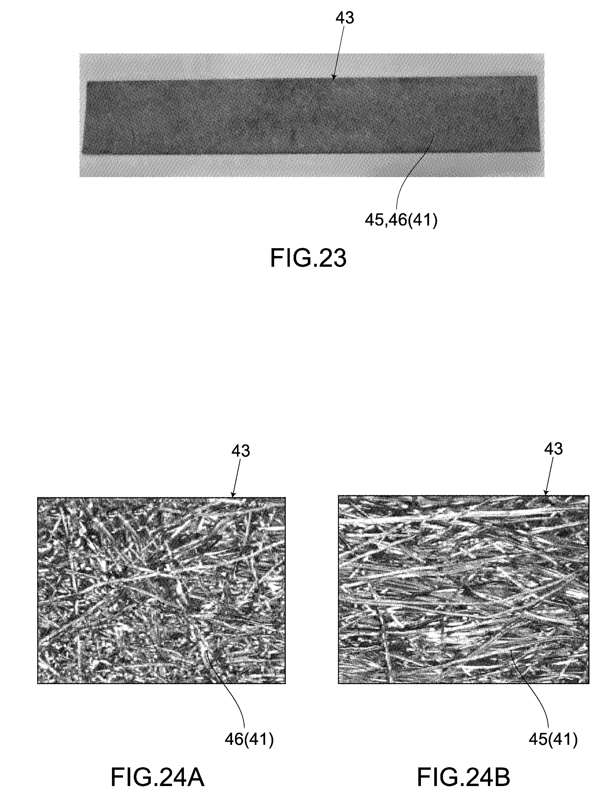
D00013

D00014

XML
uspto.report is an independent third-party trademark research tool that is not affiliated, endorsed, or sponsored by the United States Patent and Trademark Office (USPTO) or any other governmental organization. The information provided by uspto.report is based on publicly available data at the time of writing and is intended for informational purposes only.
While we strive to provide accurate and up-to-date information, we do not guarantee the accuracy, completeness, reliability, or suitability of the information displayed on this site. The use of this site is at your own risk. Any reliance you place on such information is therefore strictly at your own risk.
All official trademark data, including owner information, should be verified by visiting the official USPTO website at www.uspto.gov. This site is not intended to replace professional legal advice and should not be used as a substitute for consulting with a legal professional who is knowledgeable about trademark law.