Heat Dissipation Device With Fan Holder
XIA; BEN-FAN
U.S. patent application number 13/216188 was filed with the patent office on 2012-12-27 for heat dissipation device with fan holder. This patent application is currently assigned to FOXCONN TECHNOLOGY CO., LTD.. Invention is credited to BEN-FAN XIA.
| Application Number | 20120325431 13/216188 |
| Document ID | / |
| Family ID | 47360716 |
| Filed Date | 2012-12-27 |


| United States Patent Application | 20120325431 |
| Kind Code | A1 |
| XIA; BEN-FAN | December 27, 2012 |
HEAT DISSIPATION DEVICE WITH FAN HOLDER
Abstract
A heat dissipation device adapted for dissipating heat generated by an electronic component mounted on a printed circuit board. The heat dissipation device includes a heat sink attached to the electronic component, a fan, and a fan holder. The fan includes a frame and a rotor received in the frame. The fan holder mounts the fan onto the heat sink and includes a base fixed on the heat sink, four clasps extending upward from four corners of a top surface of the base, and four elastic portions corresponding to the clasps and configured to resiliently urge the frame of the fan. The frame of the fan is arranged on the base of the fan holder and sandwiched between the clasps and the elastic portions.
| Inventors: | XIA; BEN-FAN; (KunShan City, CN) |
| Assignee: | FOXCONN TECHNOLOGY CO.,
LTD. Tu-Cheng TW FURUI PRECISE COMPONENT (KUNSHAN) CO., LTD. KunShan City CN |
| Family ID: | 47360716 |
| Appl. No.: | 13/216188 |
| Filed: | August 23, 2011 |
| Current U.S. Class: | 165/67 |
| Current CPC Class: | H01L 23/4006 20130101; H01L 2924/0002 20130101; H01L 2924/00 20130101; H01L 23/467 20130101; H01L 2924/0002 20130101 |
| Class at Publication: | 165/67 |
| International Class: | F28F 9/00 20060101 F28F009/00 |
Foreign Application Data
| Date | Code | Application Number |
|---|---|---|
| Jun 22, 2011 | CN | 201110169050.9 |
Claims
1. A heat dissipation device comprising: a heat sink comprising a plurality of fins; a fan, the fan comprising a frame and a rotor received in the frame; and a fan holder mounting the fan onto the heat sink, the fan holder comprising a base fixed on the heat sink, four clasps extending upwardly from four corners of a top surface of the base, and four elastic portions corresponding to the clasps and configured to resiliently urge the frame of the fan, wherein the frame of the fan is arranged on the base of the fan holder and sandwiched between the clasps and the elastic portions.
2. The heat dissipation device of claim 1, wherein the frame of the fan comprises a bottom plate, and each of the clasps comprises a first portion extending upwardly from the top surface of the base, and a second portion extending from a top free end of the first portion toward to a center of the base for clasping the bottom plate of the fan.
3. The heat dissipation device of claim 2, wherein the second portion of each of the clasps extends perpendicularly from the top free end of the first portion, and the clasp has an L-shaped configuration.
4. The heat dissipation device of claim 2, wherein the second portion of each of the clasps extends inclinedly downward from the top free end of the first portion.
5. The heat dissipation device of claim 1, wherein the elastic portions are arranged at a same side of the corresponding clasps.
6. The heat dissipation device of claim 1, wherein each of the elastic portions comprises a first end connected to the base, and a free end adjacent to the corresponding clasp.
7. The heat dissipation device of claim 5, wherein the free end of each elastic portion includes an arc protrusion, and the arc protrusion is resiliently locked with the frame of the fan at the top surface of the base.
8. The heat dissipation device of claim 1, wherein the base, the clasps and the elastic portions of the fan holder are integrally formed as a single monolithic piece of metal.
9. The heat dissipation device of claim 1, wherein the four clasps are radially symmetrical with respect to each other about a center of the fan holder.
10. The heat dissipation device of claim 1, wherein a height of each of the clasps is greater than that of the corresponding elastic portion.
11. The heat dissipation device of claim 1, wherein the fins of the heat sink are divided into four groups, with the fins of the four groups oriented in four different directions, and the fins of two neighboring groups oriented perpendicularly to each other.
12. The heat dissipation device of claim 1, wherein the frame of the fan comprises a bottom plate, and the bottom plate is arranged on the base of the fan holder and sandwiched between the clasps and the elastic portions.
13. A fan holder for mounting a fan onto a heat sink, the fan comprising a frame and a rotor received in the frame, the fan holder comprising: a base for supporting the frame of the fan thereon; a plurality of clasps extending up from the base for clasping an upper side of the frame, and a plurality of elastic portions extending up from the base and corresponding to the clasps, the elastic portions being adapted for resiliently abutting against a bottom side of the frame thereby exerting an upward force on the frame and clamping the frame in the clasps.
14. The fan holder of claim 13, wherein each of the clasps comprises a first portion extending upwardly from the top surface of the base, and a second portion extending perpendicularly from a top free end of the first portion.
15. The fan holder of claim 13, wherein each of the clasps comprises a first portion extending upwardly from the top surface of the base, and a second portion extending inclinedly downward from a top free end of the first portion.
16. The fan holder of claim 13, wherein each of the elastic portions comprises a first end connected to the base and a free end adjacent to the corresponding clasp, and the free end of the elastic portion includes an arc protrusion.
17. The fan holder of claim 14, wherein the plurality of clasps is four clasps arranged on four corners of the base, the clasp being radially symmetrical with respect to each other about a center of the fan holder, and the elastic potions are arranged at a same side of the corresponding clasps.
Description
BACKGROUND
[0001] 1. Technical Field
[0002] The present invention relates to a heat dissipation device having a fan holder for mounting a fan onto a heat sink of the heat dissipation device, wherein the fan can be easily attached and detached.
[0003] 2. Description of Related Art
[0004] It is well known that during their operation, computer electronic devices such as central processing units (CPUs) can generate large amounts of heat. The heat must be quickly removed to prevent the electronic device from becoming unstable or being damaged. Typically, a heat sink combined with a fan is attached to the electronic device to dissipate heat therefrom.
[0005] Conventionally, the fan is fixed onto the heat sink with screws. However, from time to time it is necessary to detach the fan from the heat sink after dust particles have accumulated in the fan and the heat sink, so that the fan and the heat sink can be cleaned. Otherwise, the heat dissipation efficiency of the heat sink will be reduced and the lifespan of the fan will be shortened. After cleaning the fan and heat sink, the fan has to attached onto the heat sink again. Both the detaching and attaching require rotating the screws by using a screwdriver. These unscrewing and screwing operations are laborious and time-consuming. In addition, in the processes of detaching or attaching, the screws or screwdriver may be dropped and cause damage to computer components.
[0006] What is needed, therefore, is a heat dissipation device having a fan which can be easily attached to and detached from the heat dissipation device.
BRIEF DESCRIPTION OF THE DRAWINGS
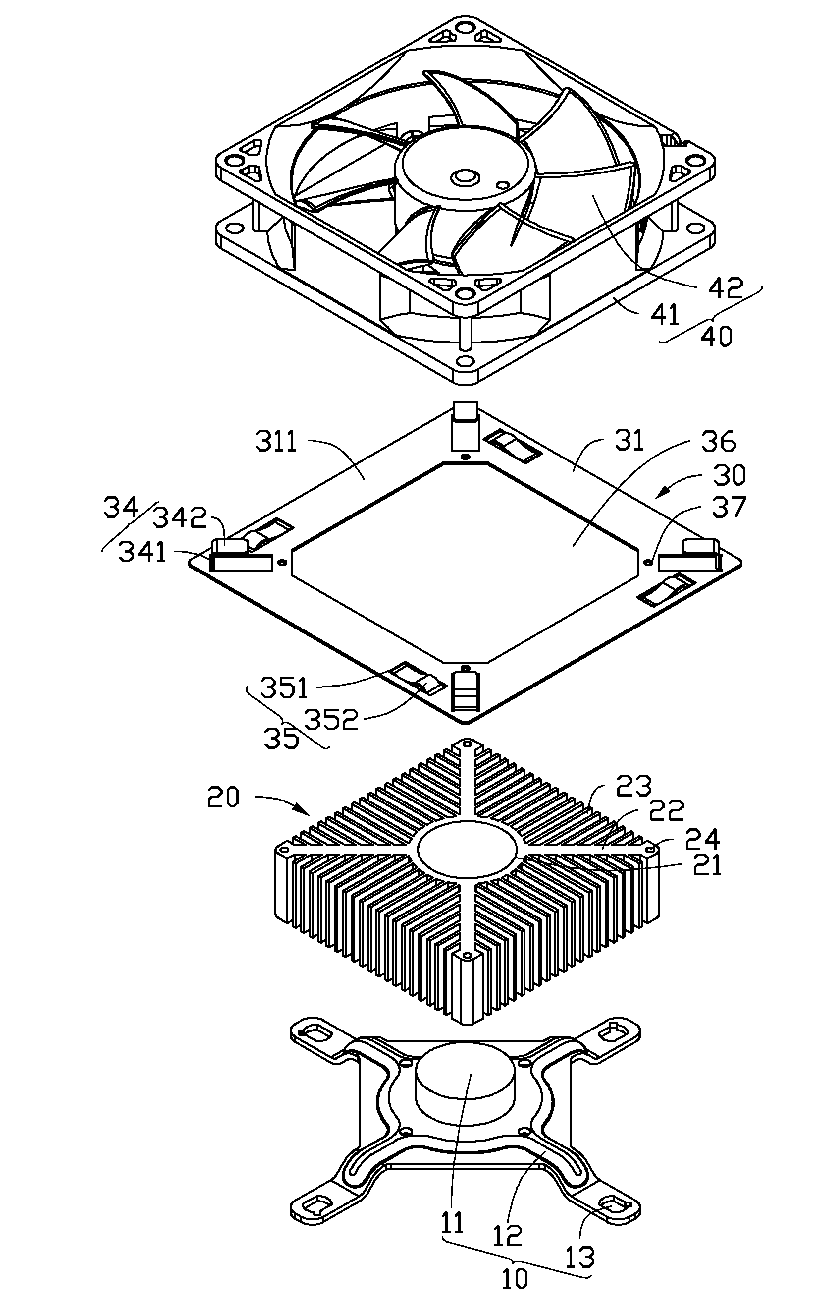
[0007] FIG. 1 is an exploded, isometric view of a heat dissipation device in accordance with an exemplary embodiment.
[0008] FIG. 2 is a partly assembled view of the heat dissipation device of FIG. 1.
[0009] FIG. 3 is similar to FIG. 2, but showing the heat dissipation device fully assembled.
DETAILED DESCRIPTION
[0010] Referring to FIG. 1, an exemplary heat dissipation device is shown. The heat dissipation device is for dissipating heat generated by an electronic component (not shown) mounted on a printed circuit board (not shown). The heat dissipation device comprises a retainer 10, a heat sink 20, a fan holder 30 and a fan 40. The fan 40 is mounted to the heat sink 20 via the fan holder 30.
[0011] The retainer 10 includes a central cylinder post 11, and four symmetrical fasteners 12 extending outwardly from the post 11. The post 11 is arranged on the electronic component to absorb the heat generated by the electronic component. Each fastener 12 defines a through hole 13 at a free end thereof. In the present embodiment, the post 11 is made of metal with good heat dissipation efficiency, such as copper. The four fasteners 12 are integrally formed as a single monolithic piece of metal.
[0012] The heat sink 20 comprises a cylinder core 21, and four symmetrical branches 22 extending outwardly from the core 21. The core 21 defines a blind hole (not shown) at a bottom thereof to receive the post 11. A plurality of fins 23 projects outwardly from the outer side surfaces of the core 21 and the branches 22. The plurality of fins 23 cooperatively define four lateral outer surfaces joined end to end, with the four lateral outer surfaces having a square configuration. Thus, the heat sink 10 correspondingly has a square configuration. The plurality of fins 23 can be divided into four groups of fins 23, with the fins 23 of the four groups oriented in four different directions. Four side surfaces of the core 21 and the four branches 22 cooperatively form four regions. Each group of the fins 23 is formed at a corresponding region. The fins 23 in two neighboring groups of the fins 23 are oriented perpendicularly to each other. Four assembly holes 24 are formed at distal ends of the four branches 22, respectively.
[0013] The fan has a square configuration, and comprises a top plate (not labeled) and a bottom plate 41 engaged with the top plate to define a frame. A rotor 42 is received in the frame.
[0014] The fan holder 30 is mounted on the heat sink 20, and includes a base 31, four clasps 34 arranged on four corners of the base 31, and four elastic portions 35 corresponding to the clasps 34, respectively. Each elastic portion 35 is arranged at the same side of the corresponding clasp 34. In the present embodiment, each elastic portion 35 is arranged at a clockwise side of the corresponding clasp 34. The four clasps 34 are centrosymmetric (and radially symmetrical) with respect to a central axis of the fan holder 30. The four elastic portions 35 are radially symmetrical with respect to the central axis of the fan holder 30. The base 31 is planar and square, and defines a substantially square opening 36 at the center thereof. In the present embodiment, the fan holder 30 is integrally formed as a single monolithic piece of metal. In other words, the base 31, the clasps 34 and the elastic portion 35 are portions of a single body formed from the same metallic material.
[0015] Each of the clasps 34 is L-shaped, and includes a first portion 341 extending upwardly from a top surface 311 of the base 31 and a second portion 342 extending perpendicularly inward from a top free end of the first portion 341. The second portion 342 is parallel to the top surface 311 of the base 31. In alternative embodiments, the second portion 342 can extend inclinedly downward from the top free end of the first portion 341. In the present embodiment, the elastic portions 35 are in the form of spring fingers. Each of the elastic portions 35 includes a first end 351 away from the corresponding clasp 34 and connected to the base 31, and an opposite, free second end 352 adjacent to the corresponding clasp 34. The second end 352 of the elastic portion 35 is located at the top surface 311 of the base 31, and includes an arced protrusion. A free end of the arced protrusion is inclined relative to the top surface 311 of the base 31. In the present embodiment, a height of the clasp 34 is higher than that of the corresponding elastic portion 35. The base 31 defines four through holes 37 corresponding to the four assembly holes 24 of the heat sink 20.
[0016] Also referring to FIG. 2, in assembly, the post 11 of the retainer 10 is received in the core 21 of the heat sink 20. Thereby, the heat sink 20 is fixed on the retainer 10. Four screws (not shown) are extended through the through holes 13 of the retainer 10 to fix the retainer 10 and the heat sink 20 on an external device, such as the printed circuit board (not shown). The electronic component is thermally connected to a bottom surface of the post 11. The fan holder 30 covers a periphery of a top end of the heat sink 20. In the present embodiment, the heat dissipation device further includes four fasteners (not shown). Each fastener extends through a corresponding through hole 37 and a corresponding assembly hole 24 to fix the fan holder 30 on the heat sink 20. The opening 36 of the fan holder 30 is configured to allow passage of airflow generated by the fan 40 therethrough, so that the airflow reaches the heat sink 20.
[0017] The fan 40 is arranged on the base 31 of the fan holder 30 in a rotationally offset position. The four corners of the bottom plate 41 of the fan 40 are pressed against the elastic portions 35 of the fan holder 30, respectively. The fan 40 is rotated anticlockwise to engage the fan holder 30 with the bottom plate 41 of the fan 40. The elastic portions 35 resiliently urge the bottom plate 41 of the fan 40 in an upward direction. As a result, the second portions 342 of the clasps 34 clasp the four corners of the bottom plate 41 of the fan 40. In other words, the four corners of the bottom plate 41 are elastically sandwiched between the elastic portions 35 and the second portions 342 of the clasps 34. Thus, the fan 40 is firmly secured on the fan holder 30.
[0018] When the fan 40 needs to be detached from the heat sink 20, the fan 40 is pressed downward and rotated clockwise to separate the bottom plate 41 of the fan 40 from the resilient clasping of the fan holder 30. Then, the fan 40 is pulled up from the fan holder 30. Thus, the fan 40 is detached from the fan holder 30.
[0019] By utilizing the clasps 34 and the elastic portions 35, the fan 40 can be easily attached to and detached from the fan holder 30.
[0020] It is to be further understood that even though numerous characteristics and advantages have been set forth in the foregoing description of embodiments, together with details of the structures and functions of the embodiments, the disclosure is illustrative only; and that changes may be made in detail, especially in matters of shape, size, and arrangement of parts within the principles of the disclosure to the full extent indicated by the broad general meaning of the terms in which the appended claims are expressed.
* * * * *
D00000
D00001
D00002
D00003
XML
uspto.report is an independent third-party trademark research tool that is not affiliated, endorsed, or sponsored by the United States Patent and Trademark Office (USPTO) or any other governmental organization. The information provided by uspto.report is based on publicly available data at the time of writing and is intended for informational purposes only.
While we strive to provide accurate and up-to-date information, we do not guarantee the accuracy, completeness, reliability, or suitability of the information displayed on this site. The use of this site is at your own risk. Any reliance you place on such information is therefore strictly at your own risk.
All official trademark data, including owner information, should be verified by visiting the official USPTO website at www.uspto.gov. This site is not intended to replace professional legal advice and should not be used as a substitute for consulting with a legal professional who is knowledgeable about trademark law.