Method And Apparatus For Dehumidifying Atmospheric Moisture And Purifying Same
Mayer; Richard
U.S. patent application number 13/530575 was filed with the patent office on 2012-12-27 for method and apparatus for dehumidifying atmospheric moisture and purifying same. Invention is credited to Richard Mayer.
| Application Number | 20120325343 13/530575 |
| Document ID | / |
| Family ID | 47360695 |
| Filed Date | 2012-12-27 |

| United States Patent Application | 20120325343 |
| Kind Code | A1 |
| Mayer; Richard | December 27, 2012 |
METHOD AND APPARATUS FOR DEHUMIDIFYING ATMOSPHERIC MOISTURE AND PURIFYING SAME
Abstract
A method and apparatus for the extraction of atmospheric moisture and converting it into potable water that is entirely closed and sealed thereby reducing the possibility of bacterial contamination through the system. The water is collected through a compressor and a coil, then filtered through a series of filters and pumped thereafter into a sealed, pressurized bladder that keeps the filtered water unexposed to the atmosphere until it is dispensed for drinking.
| Inventors: | Mayer; Richard; (Chatsworth, CA) |
| Family ID: | 47360695 |
| Appl. No.: | 13/530575 |
| Filed: | June 22, 2012 |
Related U.S. Patent Documents
| Application Number | Filing Date | Patent Number | ||
|---|---|---|---|---|
| 61571338 | Jun 23, 2011 | |||
| Current U.S. Class: | 137/544 |
| Current CPC Class: | Y02A 20/00 20180101; C02F 9/00 20130101; C02F 1/04 20130101; F24F 3/16 20130101; F24F 3/1405 20130101; Y02A 20/109 20180101; Y10T 137/794 20150401; B67D 3/0038 20130101; Y02A 20/152 20180101; C02F 2303/04 20130101; Y02A 20/154 20180101; B01D 5/0006 20130101; B67D 2210/0001 20130101; E03B 3/28 20130101; F24F 2013/228 20130101; F24F 13/222 20130101 |
| Class at Publication: | 137/544 |
| International Class: | E03B 7/07 20060101 E03B007/07 |
Claims
1. An apparatus for dehumidifying atmospheric moisture and purifying same comprising: a compressor; a coil; a collection tank for condensed atmospheric moisture; one or more filters; a first conduit connecting said collection tank to said one or more filters; a pump moving said moisture from said collection tank through said first conduit to said one or more filters; a sealed, pressurized tank for the collection of said moisture after filtration; a second conduit connecting said pressurized tank to said one or more filters, said pump moving said moisture from said one or more filters through said second conduit to said pressurized tank; a valve connected to said pressurized tank that when opened releases said moisture for dispensing into a vessel; and a circuit board with microprocessors for programming the activation of said pump.
2. The apparatus as defined in claim 1 wherein a floater indicator is contained in said collection tank and in communication with said circuit board wherein when said floater indicator hits a first predetermined level, said pump turns on to move said moisture through said apparatus and when said floater indicator hits a second predetermined level, said pump turns off.
3. The apparatus as defined in claim 1 wherein said second conduit contains a final filter for filtration of said moisture before collection in said pressurized tank.
4. The apparatus as defined in claim 1 wherein a sensor is located in said pressurized tank that is in communication with said circuit board wherein said pump is activated when the water level is sensed by said sensor in said pressurized tank to hit a first predetermined level and deactivated when said water level is sensed by said sensor in said pressurized tank to hit a second predetermined level.
Description
REFERENCE TO PRIOR APPLICATION
[0001] This application claims the priority of provisional application 61/571,338, filed Jun. 23, 2011 entitled METHOD AND APPARATUS FOR DEHUMIDIFYING ATMOSPHERIC MOISTURE AND PURIFYING SAME by Richard Mayer.
BACKGROUND OF THE INVENTION
[0002] 1. Field of the Invention
[0003] The present invention relates generally to the field of water producing devices and more specifically toward an improved device for extracting atmospheric moisture from the air, purifying it and dispensing it for drinking.
[0004] 2. Description of the Prior Art
[0005] In the field of water purification, there exists machines and methods that extra atmospheric humidity and convert it into potable water, Generally, such methods require a coil that gets cooled below the dew point, causing condensed water that is stored in a tank. The condensed water is then filtered and purified through a variety of processes to make the water potable.
[0006] Prior art methods include the use of ultraviolet light and filtration systems to remove pathogens, heavy metals and harmful bacteria. Prior art methods typically include a plurality of water tanks, pumps and filtration steps to ensure that the water remains safe to drink.
[0007] These prior art systems involve many parts that are subject to malfunction and repair, but more importantly, these systems do not provide a closed system for the collected water, making the growth of bacteria a constant concern.
[0008] It is the object of the present invention to improve on the prior art so that the collected water is not in a perpetual state of exposure to air and therefore in danger of growing harmful bacteria therein.
SUMMARY OF THE INVENTION
[0009] The preferred embodiment of the present invention teaches An apparatus for dehumidifying atmospheric moisture and purifying same comprising: a compressor: a coil; a collection tank for condensed atmospheric moisture; one or more filters; a first conduit connecting said collection tank to said one or more filters; a pump moving said moisture from said collection tank through said first conduit to said one or more filters; a sealed, pressurized tank for the collection of said moisture after filtration; a second conduit connecting said pressurized tank to said one or more filters, said pump moving said moisture from said one or more filters through said second conduit to said pressurized tank; a valve connected to said pressurized tank that when opened releases said moisture for dispensing into a vessel; and a circuit board with microprocessors for programming the activation of said pump.
[0010] The above embodiment can be further modified by defining that there further includes a floater indicator is contained in said collection tank and in communication with said circuit board wherein when said floater indicator hits a first predetermined level, said pump turns on to move said moisture through said apparatus and when said floater indicator hits a second predetermined level, said pump turns off.
[0011] The above embodiment can be further modified by defining that said second conduit contains a final filter for filtration of said moisture before collection in said pressurized tank.
[0012] The above embodiment can be further modified by defining that a sensor is located in said pressurized tank that is in communication with said circuit board wherein said pump is activated when the water level is sensed by said sensor in said pressurized tank to hit a first predetermined level and deactivated when said water level is sensed by said sensor in said pressurized tank to hit a second predetermined level.
BRIEF DESCRIPTION OF THE DRAWINGS
[0013] This invention can better be understood by reference to the drawings, provided for exemplary purposes, and in which:
[0014] FIG. 1 is a front view of the device with the filters exposed at the bottom.
[0015] FIG. 2 is a top view of the device uncovered to reveal the sealed, pressurized bladder that contains the purified water.
[0016] FIG. 3 is a rear view of the device showing the compressor, the coil, the pump and the circuitry that moves the water through the system.
[0017] FIG. 4 is a schematic view of all of the parts of the device of the instant invention.
DETAILED DESCRIPTION OF A PREFERRED EMBODIMENT
[0018] The instant invention provides an improved apparatus 10 and method that includes the prior art components of a compressor 12, a coil 14, a collection tank 16 and filtration systems 18. However, the instant invention provides a bladder 20 for containment of the purified water that is under pressure and void of air, thereby removing the possibility of the growth of bacteria therein.
[0019] The instant system therefore requires only on filtration step for the production of potable water. However, a second filtration step can be added in the interest of improving the taste of the water.
[0020] The instant invention includes a compressor 12, a coil 14 and a lower collection tank 16. The water 22 collected in the lower collection tank 16 is then pumped through a filtration system 18 that includes a filter for the removal of particles and heavy metals 24a, a filter for the removal of bacteria 24b and then a charcoal filter for the improvement of taste 24c. The water 22 is then moved after filtration into a sealed bladder 20 through a series of conduits 26 that has been bled so that no air remains and the bladder 20 is under pressure.
[0021] There is a float indicator 28 in the lower tank 16 to indicate when the tank 16 is full and when the system need not collect any more water 22. Once the bladder tank 20 is full, the system shuts off until the level of water 22 in the lower tank 16 reaches at level that indicates to the system that it must produce more water. A circuit board 30 inside of the apparatus 10 controls this function.
[0022] When water 22 is dispensed from the bladder 20, it is dispensed using a gravity feed 32 that is a valve that releases water therefrom. Optionally, a second filtration of charcoal can be added at this point for flavor. However, the primary objective is to purify the water with streamlined features and this objective is met with or without the use of the second charcoal filter.
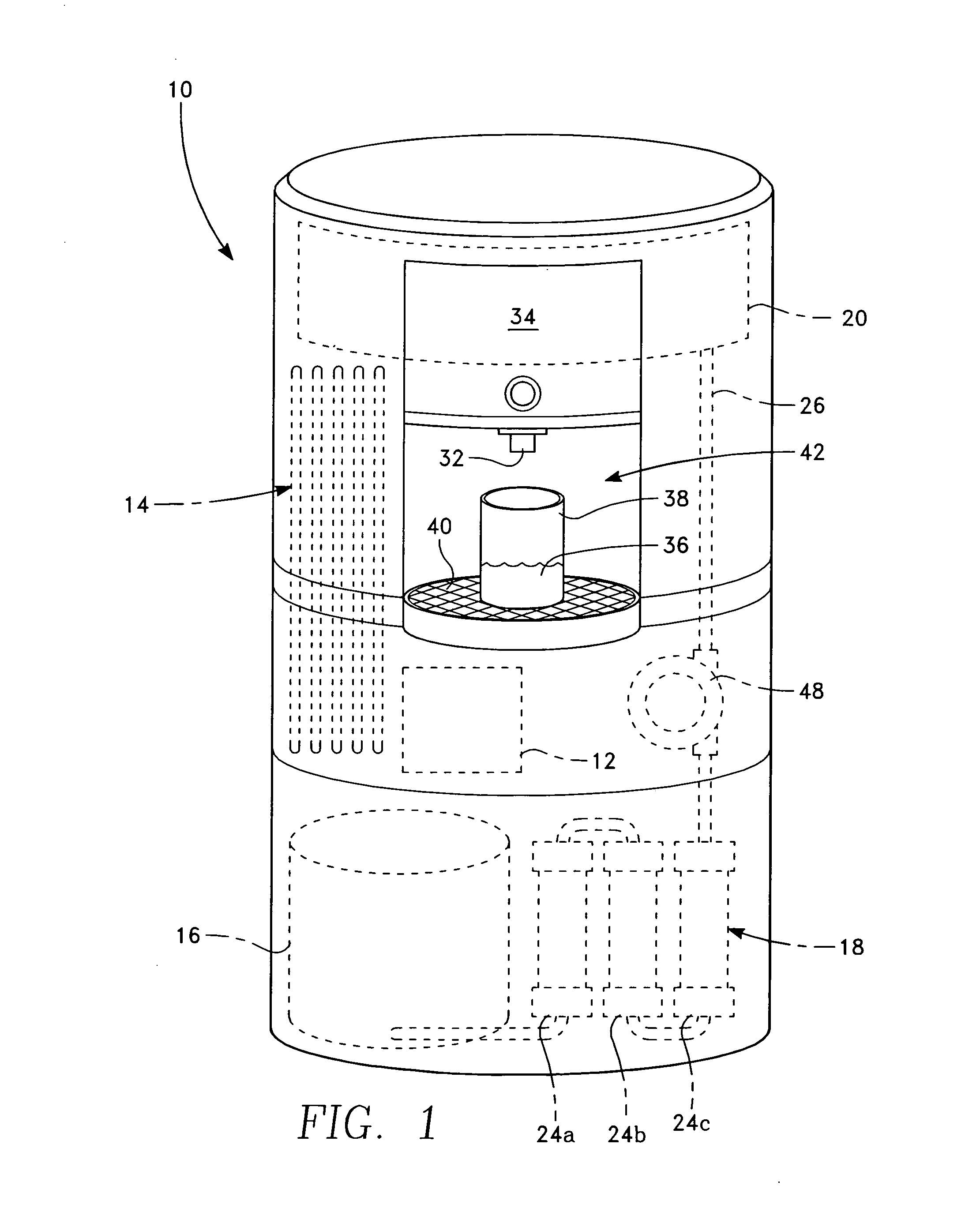
[0023] FIG. 1 shows the front 34 of the apparatus 10 where the water 36 is dispensed into a glass 38 that sits upon a shelf 40 placed below the water gravity feed 32. Below the dispensing area 42 is shown the filtration system 18 and the filters 24a, 24b, 24c through which the water 22 is filtered once condensed into the lower tank 16 which sits below the dispensing area 42.
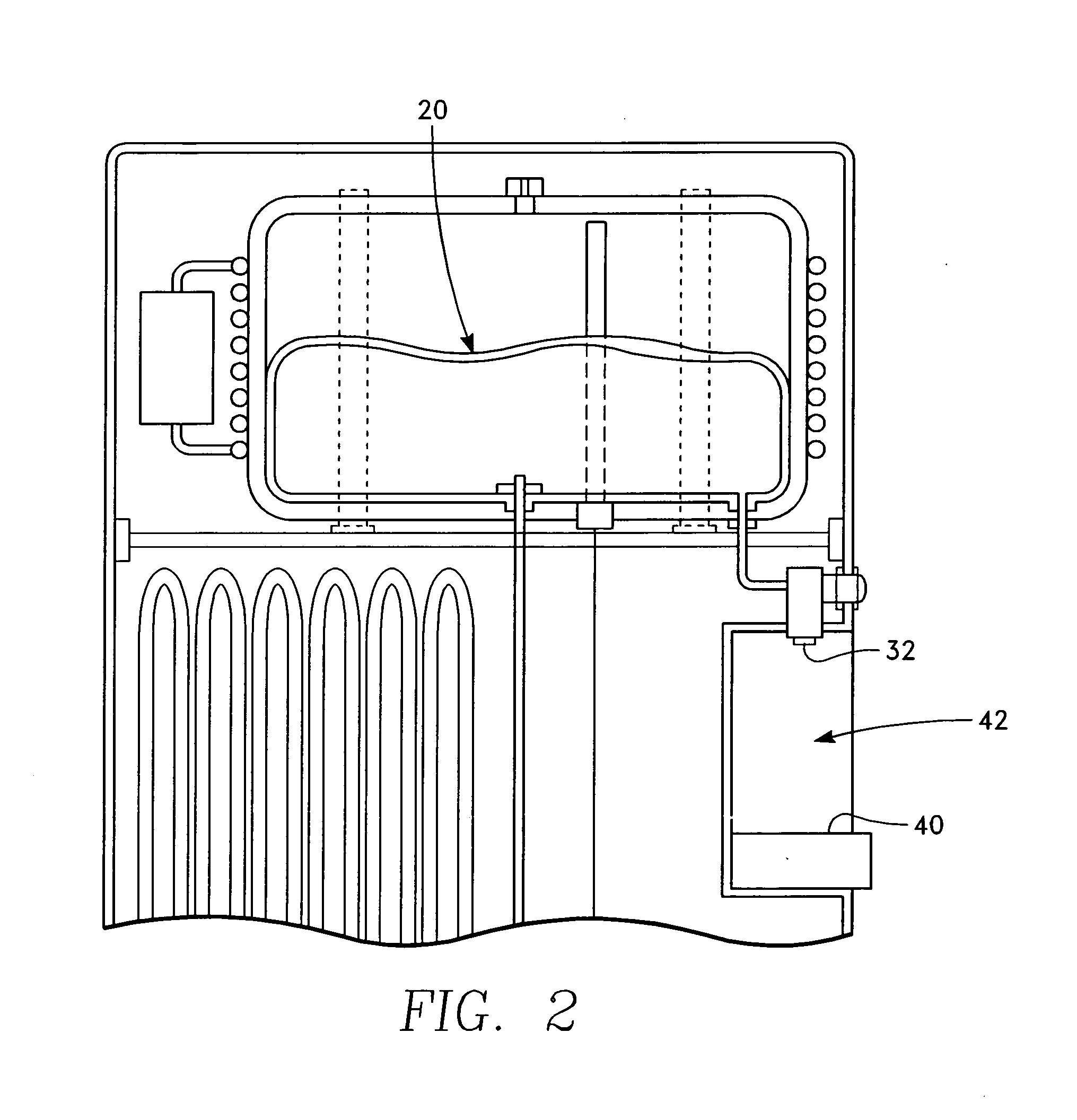
[0024] FIG. 2 shows a top view of the sealed, pressurized bladder 20 that contains the filtered and purified water 22.
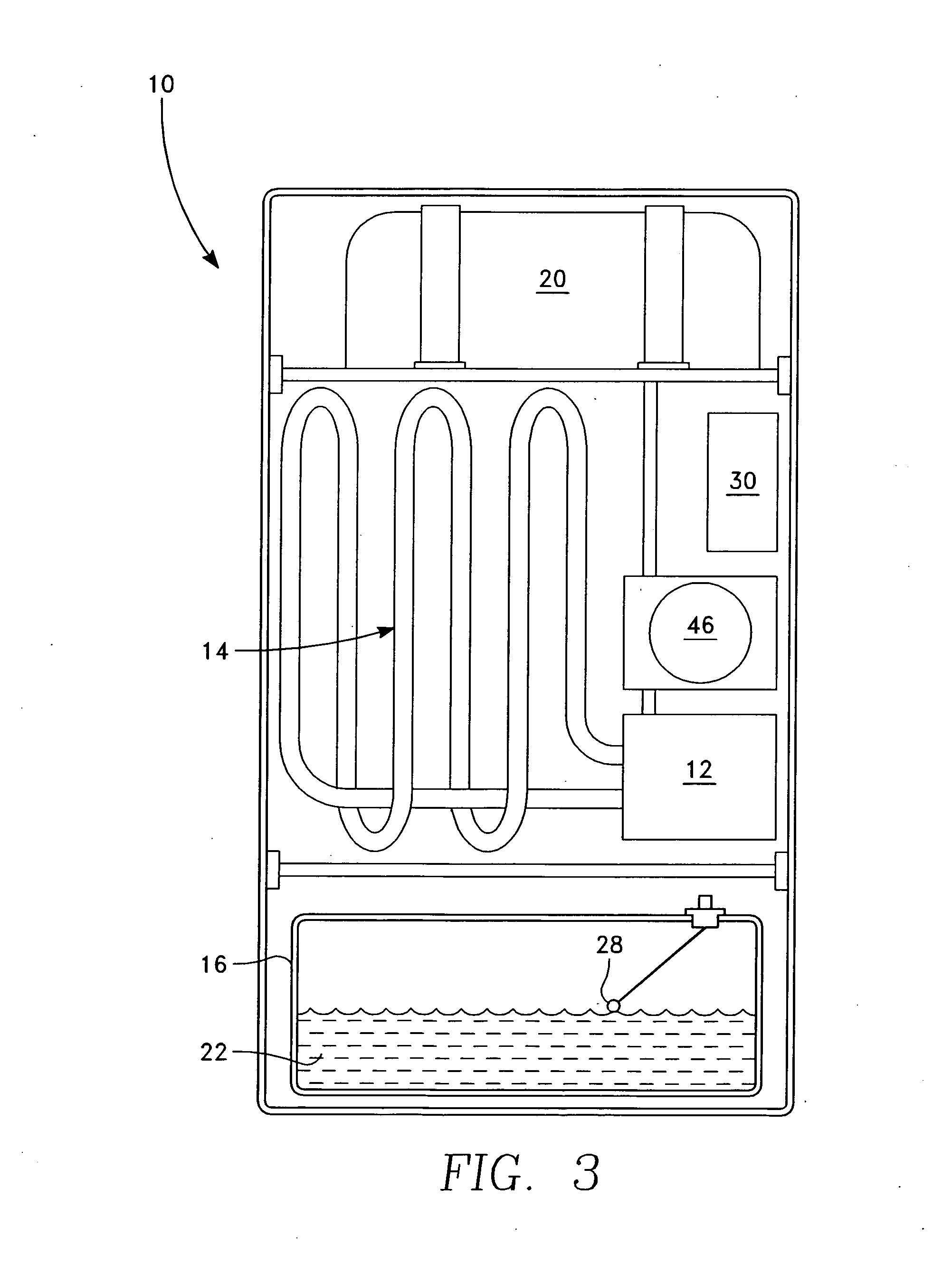
[0025] FIG. 3 shows the compressor 12, the coil 14, the pump 46 and circuitry 30 that moves the system.
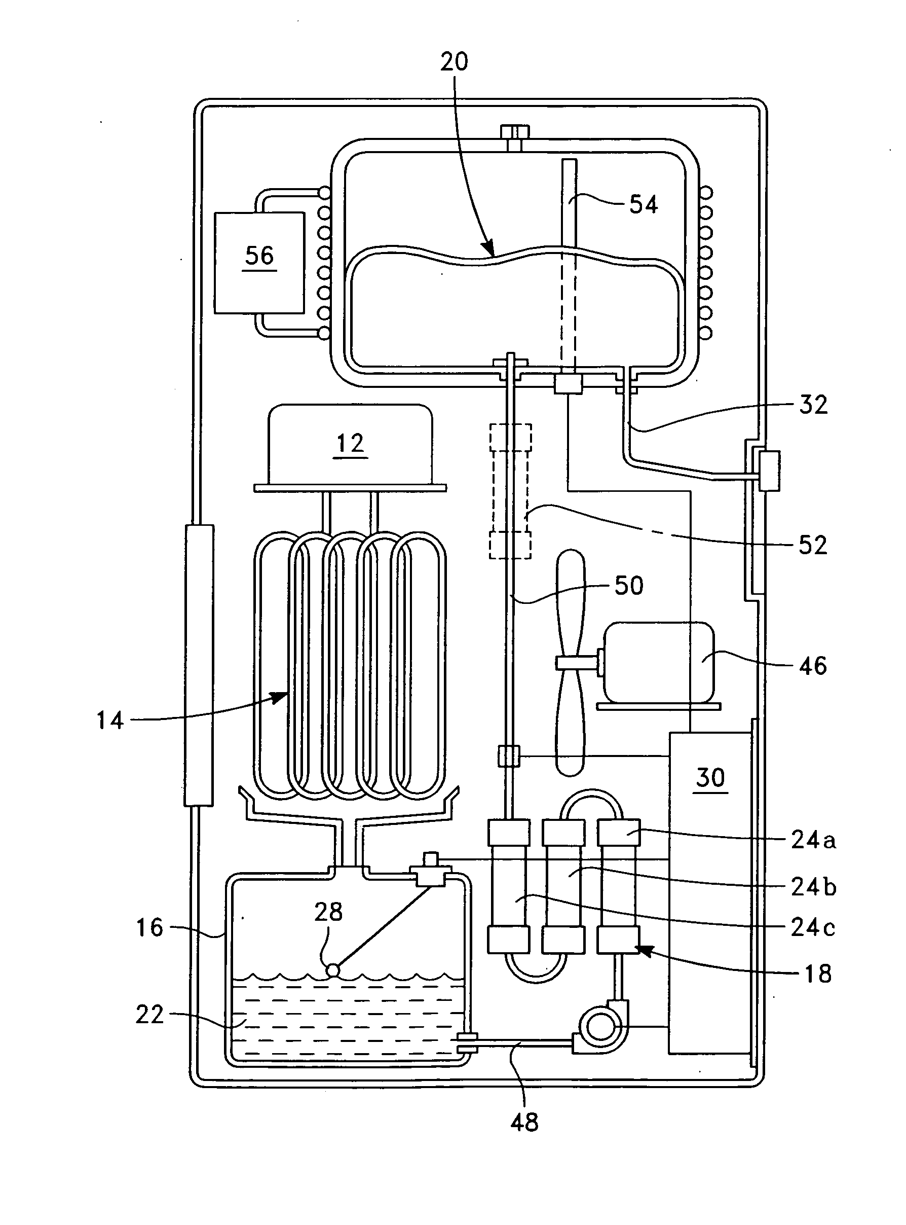
[0026] FIG. 4 shows schematically all of the components of the system. The compressor 12 cools causing atmospheric moisture to condense on the coils 14 and the condensed water 22 is then collected in the lower tank. The lower tank 16 includes the floating indicator so the system knows when the start and stop.
[0027] The collected water 22 travels through a conduit 48 into the filtration system 18 which includes at least three filtration components 24a, 24b, 24c. The circuit board 30 is the brain that responds to the floater indicator 28 in the lower tank 16 that is also in communication with the pressurized, sealed bladder 20. The pump 46 moves the water 22 through the conduit 28 into the filtration system 18 and up to the sealed bladder 20.
[0028] Between the filtration system 18 and the bladder 20 is another conduit 50 that may contain the optional second charcoal filter 52. A sensor strip 54 sits in the sealed bladder 20 and is in communication with the circuit board 30 that allows the system to know when the water level in the bladder 20 requires the system to shut off or turn on.
[0029] A cooling system 56 is attached to the bladder 20 for dispensing of the water which is a gravity feed 32 that is activated through the opening of a valve.
[0030] The discussion included in this patent is intended to serve as a basic description. The reader should be aware that the specific discussion may not explicitly describe all embodiments possible and alternatives are implicit. Also, this discussion may not fully explain the generic nature of the invention and may not explicitly show how each feature or element can actually be representative or equivalent elements. Again, these are implicitly included in this disclosure. Where the invention is described in device-oriented terminology, each element of the device implicitly performs a function. It should also be understood that a variety of changes may be made without departing from the essence of the invention. Such changes are also implicitly included in the description. These changes still fall within the scope of this invention.
[0031] Further, each of the various elements of the invention and claims may also be achieved in a variety of manners. This disclosure should be understood to encompass each such variation, be it a variation of any apparatus embodiment, a method embodiment, or even merely a variation of any element of these. Particularly, it should be understood that as the disclosure relates to elements of the invention, the words for each element may be expressed by equivalent, apparatus terms even if only the function or result is the same. Such equivalent, broader, or even more generic terms should be considered to be encompassed in the description of each element or action. Such terms can be substituted where desired to make explicit the implicitly broad coverage to which this invention is entitled. It should be understood that all actions may be expressed as a means for taking that action or as an element which causes that action. Similarly, each physical element disclosed should be understood to encompass a disclosure of the action which that physical element facilitates. Such changes and alternative terms are to be understood to be explicitly included in the description.
* * * * *
D00000
D00001
D00002
D00003
D00004
XML
uspto.report is an independent third-party trademark research tool that is not affiliated, endorsed, or sponsored by the United States Patent and Trademark Office (USPTO) or any other governmental organization. The information provided by uspto.report is based on publicly available data at the time of writing and is intended for informational purposes only.
While we strive to provide accurate and up-to-date information, we do not guarantee the accuracy, completeness, reliability, or suitability of the information displayed on this site. The use of this site is at your own risk. Any reliance you place on such information is therefore strictly at your own risk.
All official trademark data, including owner information, should be verified by visiting the official USPTO website at www.uspto.gov. This site is not intended to replace professional legal advice and should not be used as a substitute for consulting with a legal professional who is knowledgeable about trademark law.