Water Filtration System
Beatty; Scott ; et al.
U.S. patent application number 13/526727 was filed with the patent office on 2012-12-27 for water filtration system. This patent application is currently assigned to Sunbeam Products, Inc.. Invention is credited to Scott Beatty, Steven Fung, Terry Tang.
| Application Number | 20120325342 13/526727 |
| Document ID | / |
| Family ID | 47360694 |
| Filed Date | 2012-12-27 |


| United States Patent Application | 20120325342 |
| Kind Code | A1 |
| Beatty; Scott ; et al. | December 27, 2012 |
Water Filtration System
Abstract
A water filtration system is provided that includes a filter section, a tank section, a pump section, a housing section and a dispensing section. The filter section includes a high-pressure water filter disconnected from a source of tap water. The tank section includes an outer tank member and an inner tank member fluidly connected to the filter section. The pump section is fluidly connected to the filter section via a first conduit for pumping water at a high pressure through the filter and is fluidly connected to the outer tank member via a second conduit for drawing unfiltered water from the outer tank member. The housing section houses at least one of the filter section, the tank section and the pump section. The dispensing section is fluidly connected to the inner tank member for dispensing filtered water.
| Inventors: | Beatty; Scott; (Coral Springs, FL) ; Tang; Terry; (Tseung Kwan O, HK) ; Fung; Steven; (Tuen Mun, HK) |
| Assignee: | Sunbeam Products, Inc. |
| Family ID: | 47360694 |
| Appl. No.: | 13/526727 |
| Filed: | June 19, 2012 |
Related U.S. Patent Documents
| Application Number | Filing Date | Patent Number | ||
|---|---|---|---|---|
| 61499559 | Jun 21, 2011 | |||
| Current U.S. Class: | 137/544 |
| Current CPC Class: | C02F 2307/10 20130101; C02F 2209/445 20130101; C02F 2209/40 20130101; C02F 9/005 20130101; C02F 2201/006 20130101; C02F 2209/02 20130101; F25D 2323/121 20130101; C02F 2201/005 20130101; Y10T 137/794 20150401; C02F 2301/043 20130101; B67D 2210/00005 20130101; C02F 1/001 20130101 |
| Class at Publication: | 137/544 |
| International Class: | E03B 7/07 20060101 E03B007/07 |
Claims
1. A water filtration system comprising: a filter section including a high-pressure water filter disconnected from a source of tap water; a tank section including an outer tank member and an inner tank member fluidly connected to the filter section; a pump section fluidly connected to the filter section via a first conduit for pumping water at a high pressure through the filter, the pump section being fluidly connected to the outer tank member via a second conduit for drawing unfiltered water from the outer tank member; a housing section housing at least one of the filter section, the tank section and the pump section; and a dispensing section fluidly connected to the inner tank member for dispensing filtered water.
2. The system of claim 1, further comprising a cooling section including a cooling sink with at least a portion disposed in the outer tank member for cooling the unfiltered water and the filtered water.
3. The system of claim 1, further comprising a collection section fluidly connected to the outer tank member.
4. The system of claim 1, wherein the housing section includes a fan aperture adjacent the cooling section and a grill over the fan aperture.
5. The system of claim 1, wherein the tank section further includes a first insulation member and a second insulation member connected to the first insulation member.
6. The system of claim 5, wherein the first insulation member and the second insulation member are configured to house the outer tank member.
7. The system of claim 1, wherein the dispensing section includes a solenoid member for controlling flow of filtered water from the inner tank member.
8. The system of claim 7, wherein the dispensing section includes a spout disposed at an exterior of the housing section and a spout paddle rotatably disposed at an exterior of the housing section.
9. The system of claim 8, wherein the spout paddle is rotatable to open or close a switch for controlling the flow of the filtered water.
10. The system of claim 9, wherein the switch is electrically communicated to the solenoid member.
11. A water filtration system comprising: an outer tank member configured to hold unfiltered water; an inner tank member disposed inside the outer tank member, the inner tank member being configured to hold filtered water and having exterior walls exposed to unfiltered water; and a cooling section disposed at the outer tank member to cool the unfiltered water and the filtered water in the inner tank member.
12. The system of claim 11, further comprising a filter section fluidly connected to the inner tank member.
13. The system of claim 12, wherein the filter section includes a high-pressure water filter disconnected from a source of tap water.
14. The system of claim 13, further comprising a pump section fluidly connected to the outer tank member and the filter section for pumping unfiltered water through the high-pressure water filter.
15. The system of claim 11, further comprising a housing section including a bottom housing member for supporting at least one of the outer tank member, the inner tank member and the cooling section, the bottom housing member being configured to rest on a household countertop.
16. The system of claim 15, further comprising a collection section fluidly connected to the outer tank member, the collection section having a reservoir to receive unfiltered water.
17. The system of claim 16, wherein the housing section has a collection aperture opening into the collection section for pouring unfiltered water through a portion of the housing section and into the reservoir.
18. The system of claim 11, further comprising a dispensing section fluidly connected to the inner tank member for dispensing filtered water, the dispensing section including a solenoid member for controlling flow of the filtered water.
19. The system of claim 11, wherein the cooling section includes a cooling sink with at least a portion disposed in the outer tank member for cooling the unfiltered water and the filtered water.
20. The system of claim 11, further comprising a first insulation member and a second insulation member connected to the first insulation member, the first insulation member and the second insulation member being configured to house the outer tank member.
Description
CROSS-REFERENCE TO RELATED APPLICATIONS
[0001] This application claims priority under 35 U.S.C. .sctn.119(e) to U.S. Provisional Patent Application No. 61/499,559, filed on Jun. 21, 2011. The entire disclosure of U.S. Provisional Patent Application No. 61/499,559 is incorporated herein by reference.
BACKGROUND OF THE INVENTION
[0002] The present invention generally relates to a water filtration system. More specifically, the present invention relates to a water filtration system for controlling the dispensing temperature of water and provides filtering and dispensing.
BACKGROUND INFORMATION
[0003] Two types of filters are used for filtering liquids such as water. The first is gravity filters which use the weight of water to flow through the filter but the filtering rate is very slow. Examples of devices that use gravity filters are pitchers and kitchen countertop appliances. The second type of filter includes faucet filters which use water pressure from the supply line to force water through the filter at a fast rate allowing for filtering and dispensing to occur at the same time. Examples of devices that use water pressure to force water through the filter include faucet filters, refrigerator filters and plumbed filtration systems. One drawback of such devices is that they must be connected to a pressurized source of water which reduces their versatility and consumer appeal. There exists in the art water filtration systems that utilize a pump to pressurize water being supplied to a filter. One known problem with such systems is controlling the dispensing temperature with residual water temperature in the filter chamber, water lines, pump, etc. that are outside of the chill tank which are at ambient temperature. The higher temperature residual water causes the temperature of the chilled water to be raised so that the water ultimately dispensed is not at the temperature of the water in the chilled water tank.
[0004] In view of the above, it will be apparent to those skilled in the art from this disclosure that there exists a need for an improved water filtration system that controls the dispensing temperature of water and provides filtering and dispensing. This invention addresses this need in the art as well as other needs, which will become apparent to those skilled in the art from this disclosure.
SUMMARY OF THE INVENTION
[0005] A water filtration system is provided that basically comprises a filter section, a tank section, a pump section, a housing section and a dispensing section. The filter section includes a high-pressure water filter disconnected from a source of tap water. The tank section includes an outer tank member and an inner tank member fluidly connected to the filter section. The pump section is fluidly connected to the filter section via a first conduit for pumping water at a high pressure through the filter. The pump section is fluidly connected to the outer tank member via a second conduit for drawing unfiltered water from the outer tank member. The housing section houses at least one of the filter section, the tank section and the pump section. The dispensing section is fluidly connected to the inner tank member for dispensing filtered water.
[0006] In another embodiment of the present invention, a water filtration system is provided that basically comprises an outer tank member, an inner tank member and a cooling section. The outer tank member is configured to hold unfiltered water. The inner tank member is disposed inside the outer tank member. The inner tank member is configured to hold filtered water and has exterior walls exposed to unfiltered water. The cooling section is disposed at the outer tank member to cool the unfiltered water and the filtered water in the inner tank member.
BRIEF DESCRIPTION OF THE DRAWINGS
[0007] Referring now to the attached drawings which form a part of this original disclosure:
[0008] FIG. 1 is a partial side cross-sectional view of a water filtration system according to an embodiment of the present invention;
[0009] FIG. 2 is a side view of the water filtration system with a portion of the housing section removed according to an embodiment of the present invention;
[0010] FIG. 3 is an exploded perspective view of the housing section of the water filtration system according to an embodiment of the present invention;
[0011] FIG. 3A is a magnified view of region A marked on FIG. 3 according to an embodiment of the present invention;
[0012] FIG. 3B is a magnified view of region B marked on FIG. 3 according to an embodiment of the present invention;
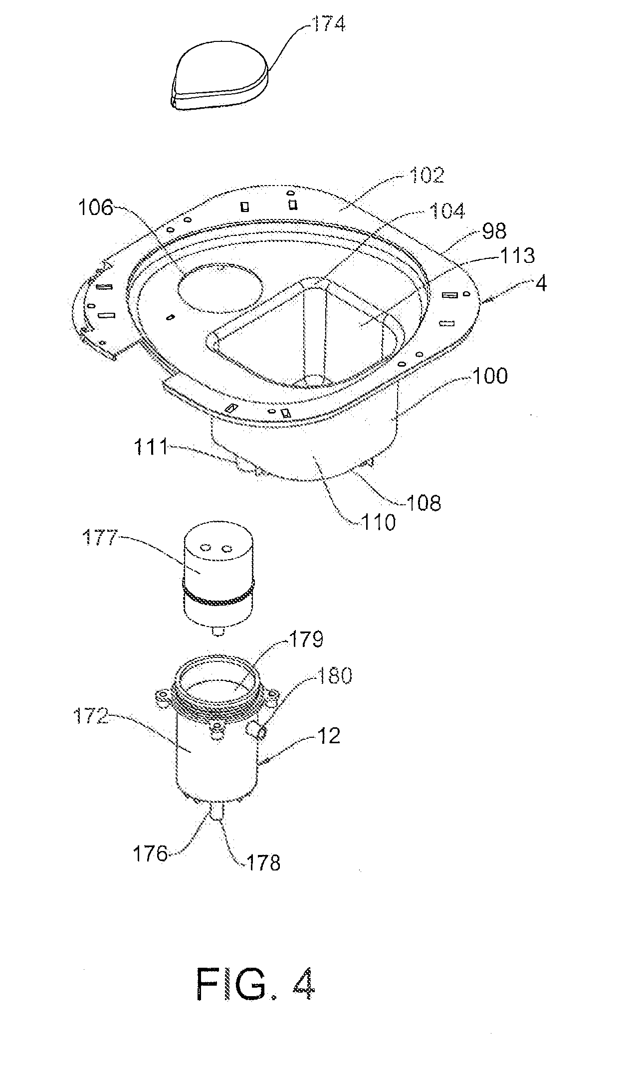
[0013] FIG. 4 is an exploded view of the collection section of the water filtration system according to an embodiment of the present invention;
[0014] FIG. 5 is an exploded and partial cross sectional view of the tank section of the water filtration system according to an embodiment of the present invention;
[0015] FIG. 6 is a partial cross sectional and perspective view of portions of the housing section, tank section, pump section and filter section of the water filtration system with portions of the housing section, the collection section, the tank section, the cooling section, the dispensing section, the control section and the display section removed for clarity according to an embodiment of the present invention;
[0016] FIG. 7 is an exploded view of the cooling section of the water filtration system according to an embodiment of the present invention;
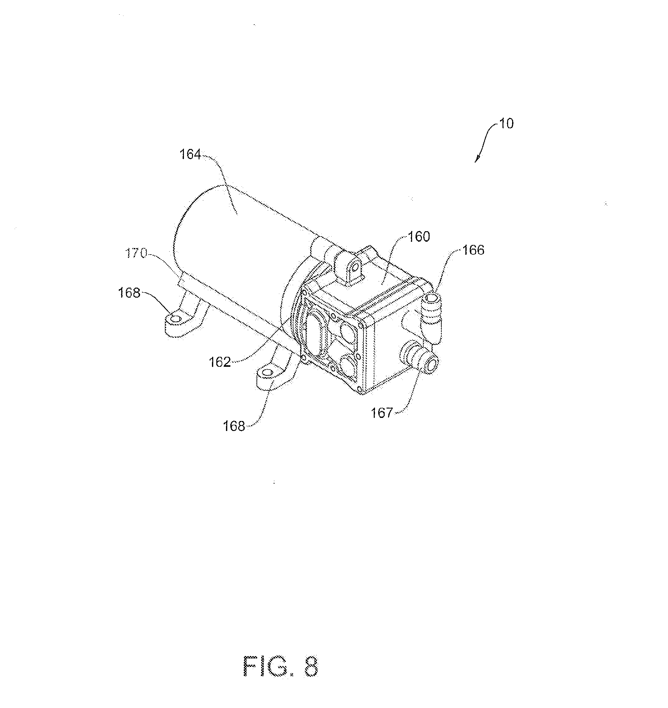
[0017] FIG. 8 is a perspective view of the pump section of the water filtration system according to an embodiment of the present invention; and
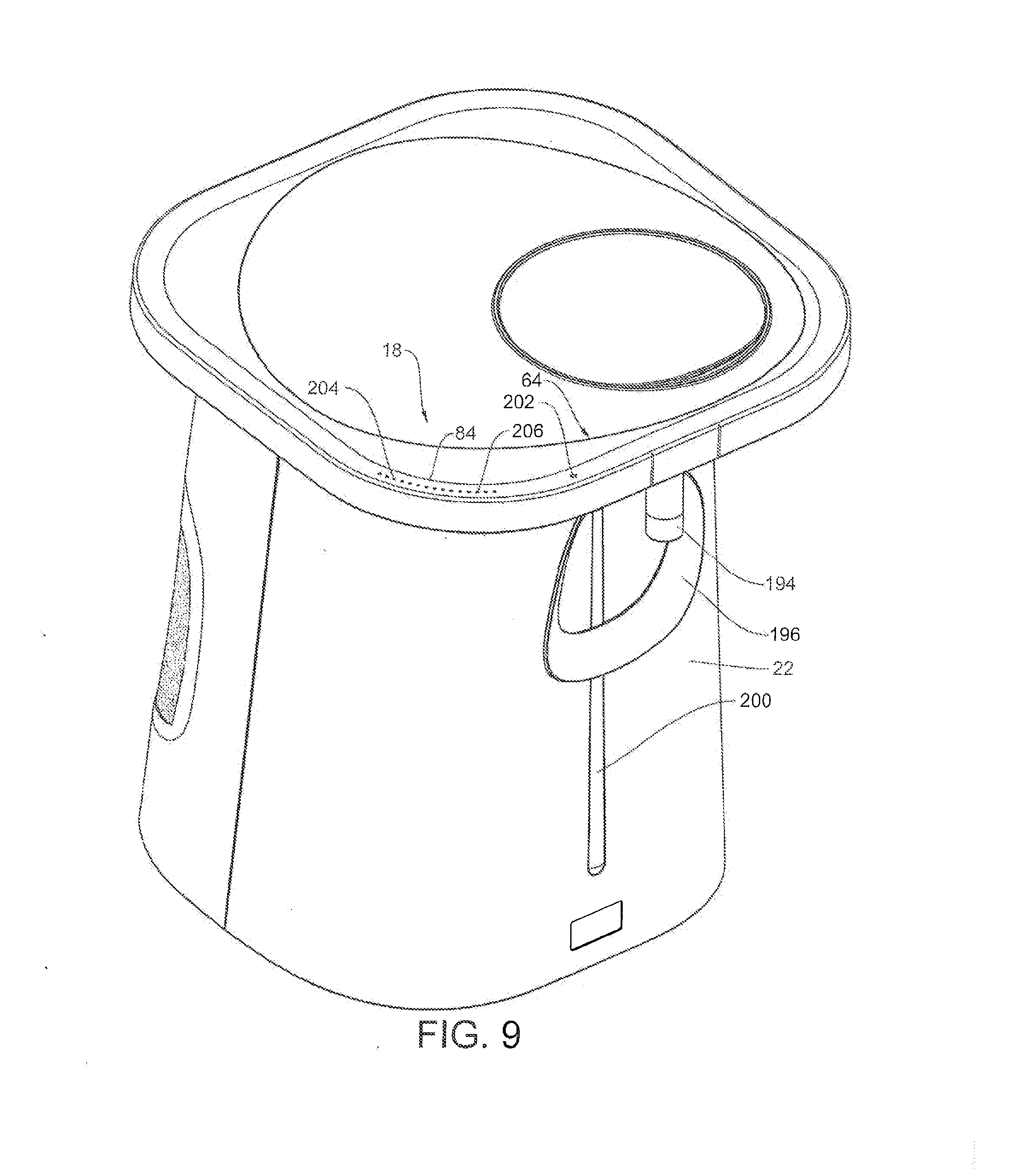
[0018] FIG. 9 is a top perspective view of the display section of the water filtration system according to an embodiment of the present invention.
DETAILED DESCRIPTION OF THE PREFERRED EMBODIMENTS
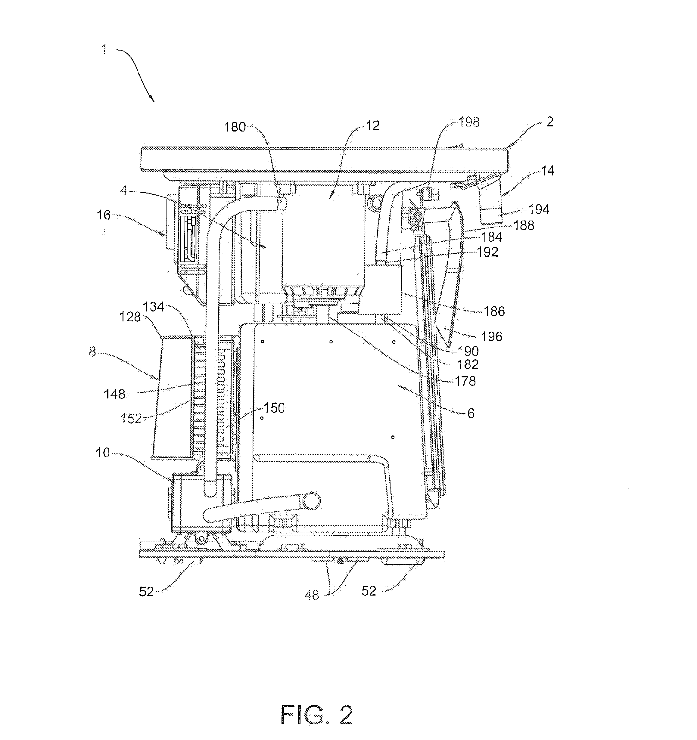
[0019] Referring initially to FIGS. 1 and 2, a water filtration system 1 is illustrated in accordance with an embodiment of the present invention. The water filtration system 1 includes a housing section 2, a collection section 4, a tank section 6, a cooling section 8, a pump section 10, a filter section 12, a dispensing section 14, a control section 16 and a display section 18.
[0020] The housing section 2 houses an assembly of the collection section 4, the tank section 6, the cooling section 8, the pump section 10, the filter section 12, the dispensing section 14, the control section 16 and the display section 18. The housing section 2 includes a first housing member 20, a second housing member 22, a bottom housing member 24, a cover member 26 and a cap member 28.
[0021] Referring to FIG. 3, the first housing member 20 is generally U-shaped and encloses about half or one side of the assembly. The first housing member 20 has an outwardly extending flange portion 30 for attaching to the cover member 26 and for supporting the collection section 4. The second housing member 22 is generally U-shaped and encloses about half or one side of the assembly. The second housing member 22 has an outwardly extending flange portion 32 for attaching to the cover member 26 and for supporting the collection section 4. The first housing member 20 is attached to the second housing member 22 by mating the U-shaped members to form a substantially rectangular cavity for the assembly to rest therein.
[0022] The first housing member 20 includes a fan aperture 34, a grill 36, a grill recess portion 38, a power switch 40 and a power switch aperture 42. The fan aperture 34 is disposed at an approximate center area of the grill recess portion 38. The grill recess portion 38 is a recessed area in the first housing member 20 that is sized and configured to receive the grill 36. The grill 36 attaches to the first housing member 20 in the grill recess portion 38 such that an exterior of the grill 36 substantially conforms with contours of an exterior of the first housing member A. The power switch aperture 42 is disposed below the grill recess portion 38 in the first housing member 20. The power switch 40 is a slide switch attached to the first housing member 20 in the power switch aperture 42.
[0023] The first housing member 20 and the second housing member 22 have mating arc shaped apertures 44, 46 that form a frame around a chill knob 48. The chill knob 48 is a rotatable knob that is attached to a rotary switch 50. The rotary switch 50 is electrically connected to the cooling section 8 and/or the control section 16 for temperature control. The chili knob 48 activates the rotary switch 50 as a user turns the chill knob 48 to control a temperature of water in the tank section 6.
[0024] The first housing member 20 and the second housing member 22 are disposed on the bottom housing member 24. At least a portion of the tank section 6 and the pump section 10 are disposed at the bottom housing member 24 as well. The bottom housing member 24 is attached to a lower portion of the first and second housing members 20, 22. The bottom housing member 24 includes one or more drain channels 52 that are configured to receive a removable plug 54. The drain channels 52 are fluidly connected to the tank section 6. The drain channels 52 extend substantially parallel to each other and extend through the bottom housing member 24. Each of the drain channels 46 is sized and configured to receive the removable plug 54 at a lower opening 56. The bottom housing member 24 further includes multiple foot rubbers 5$ that are attached to a lower face 60 of the bottom housing member 24, as shown in FIGS. 1 and 2. The foot rubbers 58 contact a surface and slightly elevate the bottom housing member 24 above the surface. The surface is generally level and can be a household countertop, for example. The cover member 26 of the housing section 2 mates with the annular flange portions 30, 32. The cover member 26 includes a top cover 62 and a refill cover 64. The refill cover 64 is removably attached to the top cover 62. The top cover 62 includes a first annular member 66 that forms a perimeter of the top cover 62. The first annular member 66 forms a downwardly facing sleeve portion 68 about its perimeter that is attached to the annular flange portions 30, 32. The sleeve portion 68 fits over the top of the annular flange portions 30, 32 to secure the cover member 26 to the first and second housing members 20, 22. The first annular member 66 also forms a cover aperture 70 within the perimeter that is sized to receive the refill cover 64. The cover aperture 70 extends through the top cover 62 to provide a passage for unfiltered water to be poured into the collection section 4. Referring to FIGS. 3 and 3A, at a border of the cover aperture 70 is an aperture wall 72 and an abutment wall 74. The abutment wall 74 is connected to the aperture wall 72 and extends inwardly from the aperture wall 72 so as to have an inner diameter smaller than that of the aperture wall 72. That is, the abutment wall 74 forms a platform 75, on which the refill cover 64 rests.
[0025] The refill cover 64 is sized and configured to fit into the top cover 62. Referring to FIGS. 3 and 3B, the refill cover 64 includes an annular band 76 extending downwardly from a lower face 78 of the refill cover 64. The annular band 76 is sized and configured to fit within the cover aperture 70 and contact an inner diameter of the abutment wall 74. An outer perimeter 80 of the lower face 78 contacts the platform 75 of the abutment wall 74. When seated in the cover aperture 70, a top face 84 of the refill cover 64 is substantially flush or aligned with a top face 86 of the top cover 62.
[0026] The refill cover 64 includes a funnel portion 88 and a refill aperture 90. The refill aperture 90 provides an ingress opening for flow of pouring water into the funnel portion 88. The funnel portion 88 extends downwardly from a border of the refill aperture 90 at a gradient for guiding the flow of pouring water into the collection section 4. The gradient of the funnel portion 88 ends at a funnel aperture 92 that is smaller than the refill aperture 90.
[0027] The cap member 28 of the housing section 2 is attached to the cover member 26. Specifically, the cap member 28 is configured to rest in the refill aperture 90 and engages walls of the refill aperture 90. The cap member 28 rests on a top face 94 of the funnel portion 88. The top face 94 forms a platform in the refill aperture 90 for contact with the cap member 28. A portion of the cap member 28 pivots away from the cover member 26 about a hinge 96 to provide space for unfiltered water to pour into the collection section 4 through the refill aperture 90.
[0028] Housing section 2 may take different forms. For example, the top cover 62 and the refill cover 64 may be integral. The annular flange portions 30, 32 may be absent. The first and second housing members 20, 22 may not be U-shaped. The cover member 26 and the cap member 28 may be integral.
[0029] Referring to FIG. 4, the collection section 4 receives unfiltered water for temporary storage before filtering. The collection section 4 rests on the annular flange portions 30, 32 and extends downwardly toward the bottom housing member 24 within the first and second housing members 20, 22. The collection section 4 includes an inner cover member 98 and a reservoir member 100 attached to the inner cover member 98. The inner cover member 98 extends radially outward from the reservoir member 100 to contact the annular flange portions 30, 32. The inner cover member 98 is disposed within the first and second housing members 20, 22 so as to cover the tank section 6, the cooling section 8, the pump section 10 and the filter section 12 above the bottom housing member 24.
[0030] The inner cover member 98 includes a second annular member 102, a reservoir aperture 104 and a filter aperture 106. The first annular member 66 fits over the second annular member 102. The reservoir aperture 104 is formed within the second annular member 102 and provides an opening to the reservoir member 100 for water. The filter aperture 106 is also formed within the second annular member 102. The filter section 12 is disposed at the filter aperture 106.
[0031] The reservoir member 100 includes a base member 108 and reservoir wall 110 attached to both the base member 108 and the inner cover member 98. The base member 108 includes an outlet 111 connected to the tank section 6. The reservoir wall 110 is an annular member extending between the base member 100 and the inner cover member 98. The reservoir member 100 receives unfiltered water poured through the cover member 26. The reservoir wall 110 forms a reservoir cavity 113 to temporarily hold the unfiltered water until allowed to flow to the tank section 6.
[0032] Referring to FIGS. 1, 2, 4 and 5, the tank section 6 includes a first insulation member 112, a second insulation member 114, an outer tank member 116 and an inner tank member 118. The first and second insulation members 112, 114 are mated to enclose the outer tank member 116. The first and second insulation members 112, 114 are comprised of an insulative material such as polypropylene insulation material. The first and second insulation members 112, 114 form rectangular apertures 120 that, when mated, receive at least a portion of the cooling section 8, which extends into the outer tank member 116 to chill the unfiltered water held by the outer tank member 116. The outer tank member 116 is fluidly connected to the outlet 111 of the reservoir member 100 via a conduit portion 122. A mesh member 124 may be disposed in the conduit portion 122 or the outlet 111 to strain solid particulates from the water in the reservoir cavity 113.
[0033] The inner tank member 118 is disposed inside the outer tank member 116. At least a portion of an exterior of the inner tank member 118 is exposed to chilled, unfiltered water in the outer tank member 116. The chilled, unfiltered water about the inner tank member 118 cools the filtered water inside the inner tank member 118. The inner tank member 118 includes an inlet 125 and an outlet 127. The inlet 125 is connected to the filter section 12 and the outlet 127 is connected to the dispensing section 14.
[0034] Referring to FIGS. 1, 2, 5 and 7, the cooling section 8 includes a first cooling cover 126, a second cooling cover 128, a cooling sink 130, a temperature sensor 132, a heat sink 134 and a cooling fan 136. The first cooling cover 126 and the second cooling cover 128 are disposed at opposite ends of the cooling section 8 from each other. The first cooling cover 126 mates with the rectangular aperture of the first and second insulation members 112, 114. The first cooling cover 126 is a solid member that can have ribs 138 for reinforcement. The first cooling cover 126 includes a sink aperture 140 that is sized and configured for the cooling sink 130. The cooling sink 130 extends through the first cooling cover 126 and into the outer tank member 116.
[0035] The cooling sink 130 includes a fin portion 142 and a sensor portion 144. Multiple fins 146 are disposed at the fin portion 142. The multiple fins 146 extend through the first cooling cover 126 and into the outer tank member 116. Unfiltered water in the outer tank member 116 contacts the fin portion 142, which cools the unfiltered water.
[0036] The temperature sensor 132 is disposed at the sensor portion 144 of the cooling sink 130. The temperature sensor 132 is electrically or wirelessly connected to the control section 16. The heat sink 134 is disposed adjacent the temperature sensor 132. The heat sink 134 includes a fin portion 148 and a base portion 150. The fin portion 148 includes multiple fins 152 that extend outwardly away from the tank section 6. The base portion 150 faces the temperature sensor 132. The fin portion 148 rests within the second cooling cover 128. End portions of the fins 152 are disposed adjacent the cooling fan 136. The second cooling cover 128 houses the cooling fan 136. The second cooling cover 128 includes a first receiving cavity 154 facing the tank section 6 and a second receiving cavity 156 facing outwardly away from the heat sink 134. The first receiving cavity 154 is configured and arranged to receive the fin portion 148. The second receiving cavity 156 is configured and arranged to receive the cooling fan 136 and secure the cooling fan 136 adjacent the fins 152. The cooling fan 136 is electrically connected to an electric motor 158, which is electrically connected to the control section 16. The grill 36 is disposed adjacent the electronic motor 158 and covers the fan 136. Referring to FIGS. 1, 2, 6 and 8, the pump section 10 includes a pump 160, a pump motor 162 and a motor housing 164. The pump 160 is fluidly connected to the filter section 12 via an outlet 166 and fluidly connected to the outer tank member 116 via inlet 167. The pump motor 162 drives the pump 160 to draw unfiltered water from the outer tank member 116, and pump it through the filter section 12 and force it and into the inner tank member 118. The motor housing 164 is a cylindrical sleeve sized to fit over the cylindrical pump motor 162. The motor housing 164 includes multiple foot members 168 connected to a bottom portion 170 of the motor housing 164. The foot members 168 are connected to the bottom housing member 24 to secure the pump section 10 to the housing section 2.
[0037] Referring now to FIGS. 2, 4, 5 and 6, the filter section 12 includes a filter receptacle member 172, a lid member 174 and a fluid flow member 176. The filter receptacle member 172 is cylindrical shaped and sized to receive a high-pressure water filter 177 in a cavity 179 framed by the filter receptacle member 172. The lid member 174 attaches to a top portion of the filter receptacle member 172 and closes the cavity 179 with the filter 177 therein. An O-ring or other type of seal may be used in conjunction with the lid member 174 to close the filter receptacle member 172 with the high-pressure water filter 177 in the cavity 179. The fluid flow member 176 includes an outlet 178 and an inlet 180. The outlet 178 is fluidly connected to the inlet 125 of the inner tank member 118. The inlet 180 is fluidly connected to the outlet 166 of the pump 160.
[0038] Referring to FIGS. 1 and 2, the dispensing section 14 is fluidly connected to the tank section 6. The dispensing section 14 draws filtered water from the inner tank member 118 of the tank section 6 and provides conduits for the water to flow out of the housing section 2.
[0039] The dispensing section 14 includes a first conduit member 182, a second conduit member 184, a solenoid member 186 and a spout member 188. The first conduit member 182 provides a passage for filtered water to flow between the inner tank member 118 and the solenoid member 186. An end portion of the first conduit member 182 is attached to the outlet 127 of the inner tank member 118 and an opposite end portion of the first conduit member 182 is attached to the solenoid member 186.
[0040] The solenoid member 186 is an electrically controlled solenoid valve that includes an inlet portion 190 and an outlet portion 192. The solenoid member 186 selectively stops or allows fluid flow between the inlet portion 190 and the outlet portion 192. The inlet portion 190 is connected to the first conduit member 192. The outlet portion 192 is fluidly connected to the spout member 188 via the second conduit member 184.
[0041] The spout member 188 dispenses filtered water and allows the user to control the flow of filtered water. The spout member 188 includes a spout 194 and a spout paddle 196. The spout 194 is fluidly connected to the outlet portion 192 via the second conduit member 184. The spout paddle 196 is pivotally disposed adjacent the annular flange portion 32, and extends downwardly therefrom. The spout paddle 196 is also electrically connected to the solenoid member 186, the pump section 10 and/or the control section 16. The spout paddle 196 pivots between a rest position and an engage position. Specifically, the spout paddle 196 is biased toward maintaining the rest position in which the paddle 196 is substantially parallel with the exterior of the second housing member 22. At the engage position, a bottom end portion of the paddle 196 contacts an exterior of the second housing member 22. When a user pivots the spout paddle 196 toward the second housing member 22 to reach the engage position, the paddle 196 closes a switch 198 thereby signaling the solenoid member 186 to open and allow the flow of filtered water from the inlet portion 190 to the outlet portion 192.
[0042] With the spout paddle 196 at the engage position, the pump motor 162 causes the pump 160 to pump unfiltered water from the outer tank member 116 through the filter section 12 and into the inner tank member 118. Filtered water that is pumped into the inner tank member 118 mixes with previously filtered water stored in the inner tank member 118. When the inner tank member 118 becomes full or substantially full, additional filtered water that enters the inner tank member 118 forces filtered water into the first conduit member 182.
[0043] The control section 16 can include a microcomputer with an operating control program that controls the pumping, cooling and dispensing, as discussed herein. The control section 16 can also include other conventional components such as a power circuit (not shown), an input interface circuit (not shown), an output interface circuit (not shown), and one or more storage devices (not shown), such as a ROM (Read Only Memory) device and a RAM (Random Access Memory) device. The power circuit is connected to an AC or DC power source and directs power to the solenoid member 186, the pump 160, the temperature sensor 132, the fan 136, etc., as well as provide power to other circuits and components of the control section 16. The input interface circuit can be electrically connected to the rotary switch 44 for temperature control, for example. The output interface circuit can be electrically connected to the display section 18, for example. The storage device stores processing results and control programs that are run by the processor circuit. The control unit 16 is capable of selectively controlling any of the cooling section 8, the pump section 10 or the display section 18 in accordance with the control program. It will be apparent to those skilled in the art from this disclosure that the precise structure and algorithms for the control section 16 can be any combination of hardware and software that will carry out the functions of the present invention. Referring to FIGS. 1, 2, 4 and 9, the display section 18 communicates a status to the user. Specifically, the display section 18 displays a collection section status, a tank section status, a cooling section status and/or a filter section status. For the collection section status, the display section 18 includes a ball check type water gauge 200 fluidly connected with the collection section 4 to display a level of stored, unfiltered water. The water gauge 200 is disposed at the second housing member 22 for easy viewing by the user.
[0044] For the tank section status and/or the cooling section status, a temperature indicator 202 is disposed at the housing section 2 for viewing by the user. Specifically; the temperature indicator 202 is located at the top face 84 of the refill cover 64. The temperature indicator 202 can indicate a specific temperature of the water in the tank section 6 or can indicate a level of cooling between a maximum level and a minimum level.
[0045] For the filter section status, the display section 18 includes a filter indicator 204. The filter indicator 204 includes a series of juxtaposed LEDs 206 disposed at the top face 84 of the refill cover 64 to indicate the remaining life of the high-pressure filter 177. The LEDs 206 may light to indicate remaining life or, in another embodiment, may light to indicate a level of use of the high-pressure filter 177.
[0046] In operation, the water filtration system 1 pumps unfiltered water through the high-pressure filter 177 and into the inner tank member 118. The pump 160 draws unfiltered water from the outer tank member 116 and pressurizes the conduit leading to the filter section 12 with the unfiltered water to force water through the high-pressure filter 177. The filtered water from the filter section 12 exits under pressure via the outlet 178 into the inner tank member 118. The newly filtered water mixes with previously-filtered, remaining water and exits the inner tank member 118 via outlet 127, traveling through conduit 182 toward the solenoid member 186. The remaining water may be filtered water that was prevented from being dispensed by the solenoid member 186 and remained in the inner tank member 118. The solenoid member 186 is activated by the spout paddle 196 moving to the engage position, thereby closing the switch 198 and activating the solenoid member 186.
[0047] The water filtration system 1 directly chills unfiltered water and indirectly chills filtered water. The outer tank member 116 does not hold water at ambient temperature. The cooling section 8, partially disposed in the outer tank member 116, chills the unfiltered water in the outer tank member 116. Thus, the unfiltered water is chilled when pumped from the outer tank member 116 and through the filter section 12.
[0048] Furthermore, the chilled, unfiltered water in the outer tank member 116 cools the exterior of the inner tank member 118 and thereby chills the filtered water within the inner tank member 118. Accordingly, when the newly-filtered water mixes with the previously-filtered water in the inner tank member 118, the temperature difference is not as great as if mixing water at ambient temperature with chilled water. Thus, the mixing of the previously-filtered water with the newly-filtered water does not substantially raise the temperature of the water to be dispensed.
GENERAL INTERPRETATION OF TERMS
[0049] In understanding the scope of the present invention, the term "comprising" and its derivatives, as used herein, are intended to be open ended terms that specify the presence of the stated features, elements, components, groups and/or steps, but do not exclude the presence of other unstated features, elements, components, grottos and/or steps. The foregoing also applies to words having similar meanings such as the terms, "including", "having" and their derivatives. Also, the terms "part," "section," "portion," "member" or "element" when used in the singular can have the dual meaning of a single part or a plurality of parts. Finally, terms of degree such as "substantially", "about" and "approximately" as used herein mean a reasonable amount of deviation of the modified term such that the end result is not significantly changed. For example, these terms can be construed as including a deviation of at least .+-.5% of the modified term if this deviation would not negate the meaning of the word it modifies.
[0050] While only selected embodiments have been chosen to illustrate the present invention, it will be apparent to those skilled in the art from this disclosure that various changes and modifications can be made herein without departing from the scope of the invention as defined in the appended claims. Furthermore, the foregoing descriptions of the embodiments according to the present invention are provided for illustration only, and not for the purpose of limiting the invention as defined by the appended claims and their equivalents.
* * * * *
D00000
D00001
D00002
D00003
D00004
D00005
D00006
D00007
D00008
D00009
XML
uspto.report is an independent third-party trademark research tool that is not affiliated, endorsed, or sponsored by the United States Patent and Trademark Office (USPTO) or any other governmental organization. The information provided by uspto.report is based on publicly available data at the time of writing and is intended for informational purposes only.
While we strive to provide accurate and up-to-date information, we do not guarantee the accuracy, completeness, reliability, or suitability of the information displayed on this site. The use of this site is at your own risk. Any reliance you place on such information is therefore strictly at your own risk.
All official trademark data, including owner information, should be verified by visiting the official USPTO website at www.uspto.gov. This site is not intended to replace professional legal advice and should not be used as a substitute for consulting with a legal professional who is knowledgeable about trademark law.