Exhaust Gas Treatment System for Engine
Shiomi; Hideo ; et al.
U.S. patent application number 13/583377 was filed with the patent office on 2012-12-27 for exhaust gas treatment system for engine. Invention is credited to Hideo Shiomi, Taichi Togashi.
| Application Number | 20120325093 13/583377 |
| Document ID | / |
| Family ID | 44563310 |
| Filed Date | 2012-12-27 |


| United States Patent Application | 20120325093 |
| Kind Code | A1 |
| Shiomi; Hideo ; et al. | December 27, 2012 |
Exhaust Gas Treatment System for Engine
Abstract
An exhaust gas aftertreatment system for an engine can perform manual regeneration control for regenerating a particulate removal filter by increasing the engine rotation speed. The system can suppress the engine rotation speed increase while maintaining the exhaust gas temperature required to regenerate the particulate removal filter. The system can set the target engine rotation speed to a first set value when a regeneration instruction signal from a manual regeneration switch is received. When, although the engine rotation speed falls within a predetermined engine rotation speed range including the first set value that is the target engine rotation speed for a predetermined time period, the exhaust gas temperature does not reach the filter's regeneration temperature within the predetermined time period, the target engine rotation speed is repeatedly reset by being increased from the first set value by a predetermined rotation speed.
| Inventors: | Shiomi; Hideo; (Osaka-shi, JP) ; Togashi; Taichi; (Osaka-shi, JP) |
| Family ID: | 44563310 |
| Appl. No.: | 13/583377 |
| Filed: | February 16, 2011 |
| PCT Filed: | February 16, 2011 |
| PCT NO: | PCT/JP2011/053231 |
| 371 Date: | September 7, 2012 |
| Current U.S. Class: | 96/425 |
| Current CPC Class: | F02D 41/0245 20130101; F01N 2560/06 20130101; F01N 2430/00 20130101; F02D 31/007 20130101; F02D 41/1446 20130101; F02D 2200/604 20130101; Y02T 10/26 20130101; F01N 3/023 20130101; F01N 9/002 20130101; F02D 41/0205 20130101; Y02T 10/12 20130101; F02D 41/029 20130101 |
| Class at Publication: | 96/425 |
| International Class: | B01D 29/62 20060101 B01D029/62 |
Foreign Application Data
| Date | Code | Application Number |
|---|---|---|
| Mar 9, 2010 | JP | 2010-052004 |
Claims
1. An exhaust gas processing system for an engine in which a filter removing particulate in exhaust gas is provided in an exhaust passage, an exhaust gas temperature sensor detecting exhaust gas temperature is provided upstream the filter, a manual regeneration means commanding regeneration of the filter, and a target engine speed is set be a first set value when a regeneration command signal from the manual regeneration means is received, characterized in that when the exhaust gas temperature does not reach the regeneration temperature of the filter until a predetermined time passes after the engine speed remains in a predetermined range of engine speed including the first set value which is the target engine speed for a predetermined time, the target engine speed is set be a value increased for a predetermined engine speed from the first set value, and after this, when the exhaust gas temperature does not reach the regeneration temperature of the filter until the predetermined time passes after the engine speed remains in a predetermined range of engine speed including the reset set value, the target engine speed is set be a value increased for the predetermined engine speed from the actual engine speed, and repeats this control.
Description
TECHNICAL FIELD
[0001] The present invention relates to an exhaust gas processing system.
BACKGROUND ART
[0002] Conventionally, an art is known reducing PM (Particulate matter) included in exhaust gas of a diesel engine with a particulate removing filter referred to as a DPF (Diesel Particulate Filter).
[0003] When the temperature of the exhaust gas is higher than regeneration temperature of the DPF, the PM collected in the DPF can be made harmless and removed. On the other hand, when the temperature of the exhaust gas is lower than regeneration temperature of the DPF, the PM collected in the DPF cannot be made harmless and removed. Then, in this case, as regeneration control of the DPF, the temperature of the exhaust gas must be made higher than the regeneration temperature regularly by using EGR and exhaust gas with excessive fuel so as to make the PM collected in the DPF harmless and remove it.
[0004] The Japanese Patent Laid Open Gazette 2004-183506 discloses construction in which, in the case of manual regeneration control of a DPF for exhaust gas, engine speed is increased to a predetermined value so as to make the temperature of the exhaust gas is higher than regeneration temperature of the DPF. The manual regeneration control is regeneration control performed based on certain manual operation by an operator.
[0005] However, in the construction disclosed by the Japanese Patent Laid Open Gazette 2004-183506, in the case of the manual regeneration control of the DPF, the engine speed is always increased to the predetermined value. Therefore, when the temperature of the exhaust gas is close to the regeneration temperature of the DPF in the operation till then, the engine speed is increased excessively and fuel is consumed uselessly.
DISCLOSURE OF INVENTION
Problems to Be Solved by the Invention
[0006] The purpose of the present invention is to provide an exhaust gas processing system performing manual regeneration control regenerating a particulate removing filter by increasing engine speed which can suppress increase of engine speed while securing regeneration temperature required for regeneration of a particulate removing filter.
Means for Solving the Problems
[0007] In an exhaust gas processing system for an engine according to the present invention, a filter removing particulate in exhaust gas is provided in an exhaust passage, an exhaust gas temperature sensor detecting exhaust gas temperature is provided upstream the filter, a manual regeneration means commanding regeneration of the filter, and a target engine speed is set be a first set value when a regeneration command signal from the manual regeneration means is received. When the exhaust gas temperature does not reach the regeneration temperature of the filter until a predetermined time passes after the engine speed remains in a predetermined range of engine speed including the first set value which is the target engine speed for a predetermined time, the target engine speed is set be a value increased for a predetermined engine speed from the first set value, and after this, when the exhaust gas temperature does not reach the regeneration temperature of the filter until the predetermined time passes after the engine speed remains in a predetermined range of engine speed including the reset set value, the target engine speed is set be a value increased for the predetermined engine speed from the actual engine speed, and repeats this control.
Effect of the Invention
[0008] According to the exhaust gas processing system of the present invention, in the manual regeneration control regenerating the particulate removing filter by increasing the engine speed, the increase of the engine speed can be suppressed while securing regeneration temperature required for the regeneration of the particulate removing filter
BRIEF DESCRIPTION OF DRAWINGS
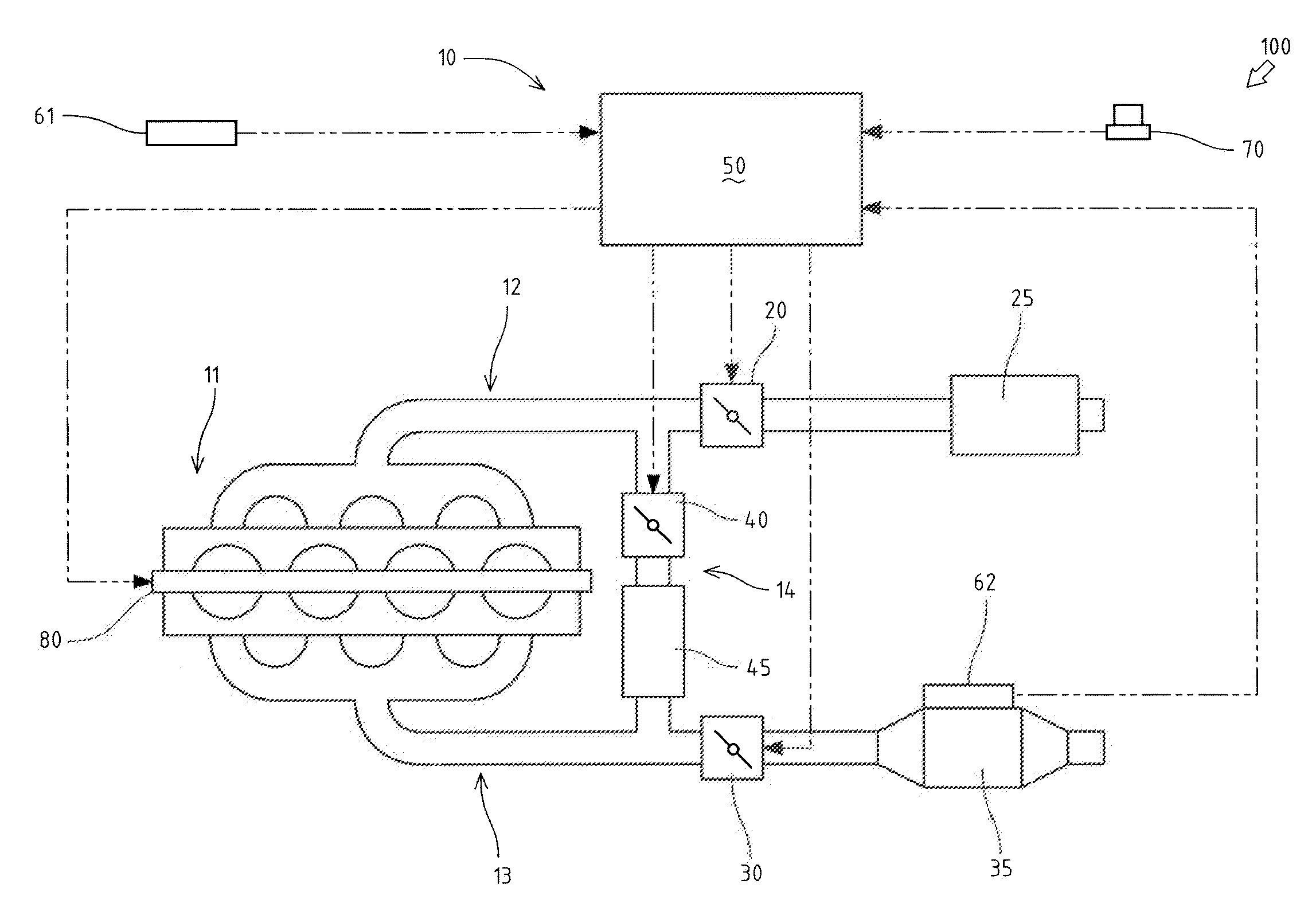
[0009] FIG. 1 A schematic drawing of an engine having an exhaust gas processing system which is an embodiment of the present invention.
[0010] FIG. 2 A flow chart of manual regeneration control.
[0011] FIG. 3 A flow chart of time series variation of the manual regeneration control.
DETAILED DESCRIPTION OF THE INVENTION
[0012] An explanation will be given on an engine 100 having an exhaust gas processing system 10 which is an embodiment of the present invention referring to FIG. 1.
[0013] The engine 100 includes a four-cylindered engine body 11, an intake route 12, an exhaust route 13, an EGR route 14, a regeneration switch 70 as a manual regeneration means, a fuel injection device 80 and an ECU (Engine Control Unit) 50.
[0014] The intake route 12 is connected to an intake manifold of the engine body 11, and has an air cleaner 25 and an intake throttle 20. The intake throttle 20 is arranged downstream the air cleaner 25 in the intake route 12.
[0015] The exhaust route 13 is connected to an exhaust manifold of the engine body 11, and has an exhaust throttle 30 and a DPF (Diesel Particulate Filter) 35 as a particulate removing filter. The exhaust throttle 30 is arranged upstream the DPF 35 in the exhaust route 13.
[0016] The EGR route 14 is connected to the part of the intake route 12 downstream the intake throttle 20 and connected to the part of the exhaust route 13 upstream the exhaust throttle 30, and has an EGR valve 40 and an EGR cooler 45.
[0017] The ECU 50 is a control means of the engine 100 and is connected to the intake throttle 20, the exhaust throttle 30, the EGR valve 40, an engine speed sensor 61, an exhaust gas temperature sensor 62, the regeneration switch 70 as the manual regeneration means, and the fuel injection device 80.
[0018] The ECU 50 controls fuel injection of the fuel injection device 80 so as to make an engine speed Ne become a target engine speed Nem, thereby controlling the engine speed Ne. The target engine speed Nem is set with a target engine speed setting means, for example an accelerator lever.
[0019] For example, in the case in which the engine 100 is mounted on a working vehicle, the regeneration switch 70 is arranged as a manual switch near an operation panel of an operator's seat. Before work with the working vehicle, an operator turns the regeneration switch 70 on so as to regenerate the DPF 35 manually.
[0020] The exhaust gas processing system 10 includes the ECU 50, the exhaust gas temperature sensor 62, the regeneration switch 70 and the fuel injection device 80, and performs regeneration control which raises exhaust gas temperature so as to make harmless PM (Particulate matters) collected in the DPF 35 and remove them when the exhaust gas temperature is lower than a regeneration temperature Th1 required for the regeneration of the DPF 35.
[0021] The exhaust gas processing system 10 in this embodiment performs manual regeneration control as discussed below. Namely, in the case of receiving a regeneration command signal, when the exhaust gas temperature is lower than the regeneration temperature Th1, the engine speed Ne is increased so as to raise the exhaust gas temperature. The not less than the regeneration temperature Th1.
[0022] An explanation will be given on a flow of the manual regeneration control referring to FIG. 2.
[0023] When the regeneration switch 70 is turned on and the regeneration command signal is received, the ECU 50 performs below manual regeneration control.
[0024] Firstly, at a step S110, the ECU 50 makes the target engine speed Nem be a first set value Ne1 set previously so as to control the engine speed Ne. In this embodiment, the first set value Nel is a low idling speed of the engine 100.
[0025] Next, at a step S120, the ECU 50 confirms whether the engine speed Ne converges at the target engine speed Nem or not. When the engine speed Ne converges at the target engine speed Nem, the control shifts to a step S130. Convergence at the target engine speed Nem means the state in which the engine speed Ne remains in a predetermined range of engine speed including the target engine speed Nem for a predetermined time.
[0026] Then, at the step S130, the ECU 50 confirms whether an exhaust temperature monitoring time t2 passes after the engine speed Ne converges at the target engine speed Nem or not. When the exhaust temperature monitoring time t2 passes, the control shifts to a step S140. The exhaust temperature monitoring time t2 is previously set and stored in the ECU 50, and enough longer than a time for increasing the engine speed Ne for a predetermined engine speed .DELTA.Ne (t1 ion FIG. 3).
[0027] At the step S140, the ECU 50 confirms whether the exhaust gas temperature. The reaches the regeneration temperature Th1 required for the regeneration of the DPF 35 or not. When the exhaust gas temperature. The does not reach the regeneration temperature Th1, the control shifts to a step S150. When the exhaust gas temperature. The reaches the regeneration temperature Th1, the actual target engine speed Nem is maintained. In this case, the PM collected in the DPF 35 is made harmless and removed. The regeneration temperature Th1 is previously stored in the ECU 50, and is the temperature which can make the PM collected in the DPF 35 harmless and remove it.
[0028] At the step S150, the ECU 50 changes the target engine speed Nem from the actual value to the value increasing the first set value Ne1 for the predetermined engine speed .DELTA.Ne, and the control shifts to the step S120 again. The predetermined engine speed .DELTA.Ne is previously set optionally and stored in the ECU 50.
[0029] An explanation will be given on an embodiment of the variation of the engine speed Ne by the manual regeneration control referring to FIG. 3.
[0030] FIG. 3 shows the time series variation of the engine speed Ne. The behavior of the engine speed Ne is described below following the time series (points A to E passing successively).
[0031] At the point A just after starting the manual regeneration control, the target engine speed Nem is set be the first set value Ne1. The engine speed Ne is controlled to converge at the first set value Ne1.
[0032] At the point B, since the exhaust temperature monitoring time t2 passes after the engine speed Ne converges at the first set value Ne1 and the exhaust gas temperature. The does not reach the regeneration temperature Th1, the target engine speed Nem set be the value increased for the predetermined engine speed .DELTA.Ne from the first set value Ne1 which is the actual value.
[0033] At the point C, the engine speed Ne is controlled to converge at the reset target engine speed Nem(Ne1+.DELTA.Ne).
[0034] At the point D, since the exhaust temperature monitoring time t2 passes after the engine speed Ne converges at the target engine speed Nem(Ne1+.DELTA.Ne) and the exhaust gas temperature. The does not reach the regeneration temperature Th1 again, the target engine speed Nem set be the value increased for the predetermined engine speed .DELTA.Ne from the target engine speed Nem(Ne1+.DELTA.Ne) which is the actual value.
[0035] At the point E, the engine speed Ne is controlled to converge at the target engine speed Nem(Ne1+2.DELTA.Ne).
[0036] After this, the same control from the point D to the point E is repeated until the exhaust gas temperature. The reaches the regeneration temperature Th1.
[0037] As mentioned above, in the exhaust gas processing system 10, after starting the manual regeneration control, when the exhaust gas temperature. The does not reach the regeneration temperature Th1 of the DPF 35 until the predetermined time passes after the engine speed Ne converges at the first set value Ne1 which is the target engine speed Nem, the target engine speed Nem is set be the value increased for the predetermined engine speed from the first set value Ne1. Then, when the exhaust gas temperature. The does not reach the regeneration temperature Th1 of the DPF 35 until the predetermined time passes after the engine speed Ne converges at the reset target engine speed Nem(Ne1+.DELTA.Ne), the target engine speed Nem is set be the value increased for the predetermined engine speed from the actual engine speed Nem(Ne1+.DELTA.Ne) and repeats this control.
[0038] In the exhaust gas processing system 10, the exhaust gas temperature. The is monitored, and when the exhaust gas temperature. The does not reach the regeneration temperature Th1, the target engine speed Nem is increased for the predetermined engine speed .DELTA.Ne for each passing of the exhaust temperature monitoring time t2 by stages, for example the target engine speed Nem(Ne1+.DELTA.Ne), the target engine speed Nem(Ne1+2.DELTA.Ne), the target engine speed Nem(Ne1+3.DELTA.Ne), and the target engine speed Nem(Ne1+4.DELTA.Ne), whereby the exhaust gas temperature. The is raised so as to reach the regeneration temperature Th1.
[0039] Therefore, excessive increase of the engine speed Ne can be suppressed while securing the regeneration temperature Th1 required for the regeneration of the DPF 35. As a result, useless consumption of fuel can be reduced.
INDUSTRIAL APPLICABILITY
[0040] The present invention can be employed in an exhaust gas processing system performing manual regeneration control regenerating a particulate removing filter by increasing engine speed.
* * * * *
D00000
D00001
D00002
D00003
XML
uspto.report is an independent third-party trademark research tool that is not affiliated, endorsed, or sponsored by the United States Patent and Trademark Office (USPTO) or any other governmental organization. The information provided by uspto.report is based on publicly available data at the time of writing and is intended for informational purposes only.
While we strive to provide accurate and up-to-date information, we do not guarantee the accuracy, completeness, reliability, or suitability of the information displayed on this site. The use of this site is at your own risk. Any reliance you place on such information is therefore strictly at your own risk.
All official trademark data, including owner information, should be verified by visiting the official USPTO website at www.uspto.gov. This site is not intended to replace professional legal advice and should not be used as a substitute for consulting with a legal professional who is knowledgeable about trademark law.