Heat Exchanger
BREHM; Holger ; et al.
U.S. patent application number 13/525698 was filed with the patent office on 2012-12-27 for heat exchanger. Invention is credited to Holger BREHM, Thomas Heckenberger, Thomas Himmer, Stephanie Larpent, Julie Paterson, Rudolf Riedel.
| Application Number | 20120324909 13/525698 |
| Document ID | / |
| Family ID | 44012439 |
| Filed Date | 2012-12-27 |

View All Diagrams
| United States Patent Application | 20120324909 |
| Kind Code | A1 |
| BREHM; Holger ; et al. | December 27, 2012 |
HEAT EXCHANGER
Abstract
A heat exchanger for exchanging heat between two media in a vehicle is provided. The heat exchanger includes at least one tube, especially a double-walled tube for carrying a first medium of a first temperature, a thermoelectric material being disposed on an inner wall of the tube, and at least one guide sheet, connected to the at least one tube, for carrying a second medium of a second temperature. The at least one guide sheet is designed to carry the second medium to the outer wall of the at least one tube to allow the exchange of heat between the first and the second medium.
| Inventors: | BREHM; Holger; (Erdmannhausen, DE) ; Heckenberger; Thomas; (Leinfelden-Echterdingen, DE) ; Himmer; Thomas; (Reichenbach, DE) ; Larpent; Stephanie; (Stuttgart, DE) ; Paterson; Julie; (Toronto, CA) ; Riedel; Rudolf; (Pforzheim, DE) |
| Family ID: | 44012439 |
| Appl. No.: | 13/525698 |
| Filed: | June 18, 2012 |
Related U.S. Patent Documents
| Application Number | Filing Date | Patent Number | ||
|---|---|---|---|---|
| PCT/EP2010/069107 | Dec 7, 2010 | |||
| 13525698 | ||||
| Current U.S. Class: | 62/3.2 |
| Current CPC Class: | F28F 2240/00 20130101; F28F 13/06 20130101; Y02T 10/16 20130101; F01N 5/025 20130101; F28F 2215/10 20130101; F01N 3/043 20130101; H01L 35/30 20130101; F28D 7/1653 20130101; F28F 1/32 20130101; F28F 2001/027 20130101; F28F 3/044 20130101; Y02T 10/20 20130101; F28D 7/1684 20130101; Y02T 10/12 20130101 |
| Class at Publication: | 62/3.2 |
| International Class: | F25B 21/02 20060101 F25B021/02 |
Foreign Application Data
| Date | Code | Application Number |
|---|---|---|
| Dec 16, 2009 | DE | 10 2009 058 676.8 |
Claims
1. A heat exchanger for exchanging heat between two media in a vehicle, the heat exchanger comprising: at least one tube configured to guide a first medium of a first temperature, a thermoelectric material disposed between an inner wall of the tube and an outer wall of the tube or on an inner wall of the tube; and at least one guide sheet connectable to the at least one tube for guiding a second medium of a second temperature, the at least one guide sheet configured to guide the second medium to the outer wall of the at least one tube to enable the exchange of heat between the first medium and the second medium.
2. The heat exchanger according to claim 1, wherein the guide sheet has at least one recess, and wherein the tube is accommodated by the recess.
3. The heat exchanger according to claim 1, wherein a second tube is arranged substantially parallel to the tube on a first common plane, and a third tube is arranged on a second plane which is parallel to the first plane, the third plane being disposed on the second plane in a position at which a passage is provided between the tube and the second tube on the first plane.
4. The heat exchanger according to claim 1, wherein the inner wall forms a guide channel for the first medium, wherein the inner wall has protrusions in the guide channel, and/or wherein the outer wall has raised structures in a direction of a flow area of the second medium.
5. The heat exchanger according to claim 1, wherein the guide sheet has a profiling.
6. The heat exchanger according to claim 5, wherein the profiling is a plurality of elongated raised structures, the plurality of raised structures being arranged on the guide sheet such that a meandering guidance of the second medium around multiple tubes is facilitated.
7. The heat exchanger according to claim 5, wherein the guide sheet has a profiling in the form of a plurality of protrusions, the guide sheet being arranged adjacent to another guide sheet having a profiling in the form of a plurality of protrusions, the protrusions of the profiling of the guide sheet engaging on a back with the protrusions of the profiling of the additional guide sheet.
8. The heat exchanger according to claim 5, wherein the guide sheet is arranged adjacent to at least one additional guide sheet having a profiling, the profiling of the guide sheet and the profiling of the additional guide sheet having a same structure and facing a same raising direction, the additional guide sheet being rotated 180 degrees with respect to a normal to the guide sheet.
9. The heat exchanger according to claim 5, wherein the guide sheet is disposed adjacent to at least one additional guide sheet having a profiling, the profiling of the guide sheet and the profiling of the additional guide sheet facing each other.
10. The heat exchanger according to claim 1, wherein the at least one guide sheet is uneven in an area of the passages in the tube.
11. The heat exchanger according to claim 1, wherein the at least one tube is a double-walled tube.
12. The heat exchanger according to claim 2, wherein the second tube and the third tube are double-walled tubes.
Description
[0001] This nonprovisional application is a continuation of International Application No. PCT/EP2010/069107, which was filed on Dec. 7, 2010, and which claims priority to German Patent Application No. DE 10 2009 058 676.8, which was filed in Germany on Dec. 16, 2009, and which are both herein incorporated by reference.
BACKGROUND OF THE INVENTION
[0002] 1. Field of the Invention
[0003] The present invention relates to a heat exchanger for exchanging heat between two media, as used, for example in a vehicle.
[0004] 2. Description of the Background Art
[0005] The energy which is stored, for example, in the exhaust gas of a vehicle in the form of heat, is currently unused and discharged into the surroundings. To increase the efficiency of a system, e.g., a motor vehicle, and consequently reduce CO.sub.2 emissions during operation, a thermoelectric generator (TEG) may be implemented whose thermoelectric module (TEM) converts part of the heat to electrical energy and returns it to the system. The TEG is a heat exchanger which is provided with thermoelectrically active material. If this material is exposed to a temperature difference, the TEG generates electrical energy. The temperature difference is produced in the TEG by conducting a hot medium, e.g., exhaust gas, and a cold medium, e.g., a coolant, past each other. The TEG mat be accommodated at any location within the exhaust gas branch or in the exhaust gas recirculation system, producing different benefits.
[0006] Conventional TEGs are not very efficient, due to the elevated heat transfer resistance between thermoelectrically active materials and a heat source/heat sink. Integrating the TEM into a heat exchanger has also proven to be not very practical. Up to now, available connecting techniques have been, in part, unstable at high temperatures. In addition, only minimal heat transfer frequently exists on the contacting of the TEM in the heat exchanger on the gas side. According to the prior art, conventional TEMs are therefore not optimally suited for use in a TEG, due to their design and connecting techniques, and are also not very effective.
[0007] EP 1 475 532 A2, which corresponds to U.S. Pat. No. 7,100,369, describes a thermoelectric generator having a thermoelectric element which uses the exhaust gas from an engine as a high temperature heat source and an engine coolant as a low temperature heat source to generate electricity. A valve regulates the supply of the exhaust gas to the thermoelectric element according to the engine load.
SUMMARY OF THE INVENTION
[0008] It is therefore an object of the present invention to provide an improved heat exchanger for exchanging heat between two media.
[0009] An embodiment of the present invention is based on the finding that an optimization of the thermoelectric generator may be achieved by designing a heat exchanger, in particular, as a cross-flow heat exchanger. As an alternative to generating electrical energy from thermal energy, the heat exchanger according to the invention may also be used as a thermoelectric heater and cooler.
[0010] The present invention provides a heat exchanger for exchanging heat between two media in a vehicle, the heat exchanger having the following features: at least one tube, in particular a double-walled tube for guiding or conducting a first medium of a first temperature, a thermoelectric material being disposed between an inner wall of the tube and an outer wall of the tube or at least on an inner wall of the tube; and at least one guide sheet connected to the at least one tube for guiding a second medium of a second temperature, the at least one guide sheet being designed to guide the second medium to the outer wall of the at least one tube to enable the exchange of heat between the first medium and the second medium.
[0011] The heat exchanger may be a thermoelectric generator for generating electric current from a temperature difference between two media. Alternatively, the heat exchanger may also be a thermoelectric heater or cooler which provides a heating or cooling capacity, using electric current. A heat exchanger of this type may be used, for example, in vehicles. If the heat exchanger according to the invention is used as a thermoelectric generator, a coolant for cooling the engine or the battery of the vehicle, for example, may be used as the first medium, and an exhaust gas generated by an internal combustion engine of the vehicle may be used as the second medium. The tube may be designed, for example, as a flat tube or a round tube. In addition, the tube may be designed as a single-walled or double-walled tube. The double-walled tube is generally formed from an inner tube and an outer tube surrounding the inner tube. In this case, the thermoelectric material is disposed between the inner tube and the outer tube. The guide sheet may be a sheet strip, along which, for example, the exhaust gas from the internal combustion engine may be guided. The heat exchanger according to the invention may have a plurality of guide sheets disposed in layers and a plurality of tubes disposed in parallel. For example, each of the guide sheets may have openings through which the plurality of tubes is accommodated and held in such a way that the tubes and guide sheets are disposed largely orthogonally to each other. Accordingly, the first medium and the second medium may be carried in a cross current without the two media mixing. The first medium may generally be guided within the tube (for example, in an inner tube of a double-walled tube), and the second medium may be guided between main surfaces of the guide sheets and around the outer walls of the tubes. Alternatively, the second medium may also be guided within the at least one tube, and the first medium may be guided along the at least one guide sheet. The thermoelectric material may be, for example, differently doped semiconductor materials. According to the design of the heat exchanger proposed herein, the thermoelectric material between the favorably cross-flowing media of different temperatures may be disposed in such a way that the thermoelectric material is equally exposed to both media, so that a temperature gradient is as homogeneous and minimal as possible over the entire heat exchanger.
[0012] According to an embodiment, the guide sheet may have at least one recess. The tube may be accommodated by the recess. According to such a design of the guide sheet and tube, a flow direction of the first medium may deviate from a flow direction of the second medium. For example, the first medium may flow largely orthogonally to the second medium. A flow relationship of this type permits better heat transfer between the first medium and the second medium than would be the case, for example, using a unidirectional flow (i.e., a flow in the same direction) of the two media. The guide sheet may also have a plurality of recesses for accommodating multiple tubes, in this case each tube being able to be accommodated in a separate recess.
[0013] According to another embodiment, at least one additional, in particular double-walled, tube may be disposed largely parallel to the tube on a first common plane, and at least one third, in particular double-walled, tube may be disposed on a second plane which is parallel to the first plane. The third tube may be disposed on the second plane in a position at which a passage between the tube and the additional tube is provided on the first plane. Such a non-aligned configuration of multiple tubes produces a meandering flow of the second medium around the tubes, which advantageously enlarges the heat transfer surface between the two media.
[0014] The inner wall of the tube may also form a guide channel for the first medium, the inner wall also being able to have protrusions into the guide channel. Additionally or alternatively, the outer wall of the tube may also have raised structures in the direction of a flow region for the second medium. Both the protrusions and the raised structures may be designed as filled or unfilled knobs, which may have different shapes. The protrusions and/or raised structures may act as a turbulence insert, for example to produce an swirling of a liquid medium. The protrusion and/or raised structures furthermore have the advantage that they may enlarge a heat transfer surface for the first medium and/or the second medium, which may improve the heat transfer coefficient.
[0015] According to another embodiment, the guide sheet may have a profiling. For example, the profiling may be designed in the form of a plurality of filled or unfilled knobs on a surface of the guide sheet. The knobs may have different geometries. The profiling may act as a spacer between the guide sheet and an adjacent guide sheet.
[0016] The profiling may be designed in the form of a plurality of elongated raised structures. The plurality of raised structures may be disposed on the guide sheet in such a way that a meandering guidance for the second medium around multiple tubes is made possible. For example the elongated raised structures may be designed as narrow, elongated knobs between two diagonally opposite tubes from two different rows of tubes disposed in parallel alignment. In this manner, the second medium may be advantageously guided or deflected along the outer wall of the tube, which makes it possible to achieve a better heat transfer with the first medium carried in the inner tube.
[0017] According to another embodiment, the guide sheet may have a profiling in the form of a plurality of protrusions. The guide sheet may be disposed adjacent to at least one additional guide sheet which has a profiling in the form of a plurality of protrusions, multiple protrusions of the profiling of the guide sheet being able to engage on the back with corresponding protrusions of the profiling of the additional guide sheet. A fixing of multiple, stacked guide sheets to each other, and thus also an improved hold for multiple tubes which engage with the stack of guide sheets, may thus be favorably provided.
[0018] Alternatively, the guide sheet may be disposed adjacent to at least one additional guide sheet having a profiling, the profiling of the guide sheet and the profiling of the additional guide sheet having the same structure and being able to face the same raising direction, the other guide sheet, however, being able to be rotated 180 degrees with regard to a normal to the guide sheet. According to this specific embodiment, therefore, the profiling of two adjacent guide sheets having identical profiling may be prevented from engaging with each other, since, for example, a distance between the guide sheets would thus be too small for certain applications or application scenarios of the heat exchanger. Since it is possible to dispense with the manufacture of differently profiled guide sheets, however, production costs may be reduced in this type of configuration of the guide sheets, since only guide sheets of the same type need to be manufactured.
[0019] The guide sheet may also be disposed adjacent to at least one additional guide sheet having a profiling, the profiling of the guide sheet and the profiling of the additional guide sheet being able to face each other. In a stack of guide sheets, therefore, two surfaces having profiling and two upper sides not having profiling may each alternately face each other. This provides the advantage that the raised structures of the profiling of both guide sheets may touch each other and thereby ensure a greater distance between the two guide sheets. For certain application scenarios, in particular for two media of higher viscosity, such a greater distance between the guide sheets may be helpful to ensure a lower resistance of the second medium between the guide sheets.
[0020] According to another embodiment, the at least one guide sheet may be uneven in the area of the passages in the tube or uneven in the area of the at least one recess. For example, the guide sheet may be corrugated in the area of the recesses. This specific embodiment of the guide sheet offers the advantage, on the one hand, that an improved hold for the at least one tube may be achieved without additional components, since a larger area of the tube is contacted and held by the guide sheet, due to the uneven form. On the other hand, an improved heat transfer may be made possible between the guide sheet and the tube, since a greater contact line exists between the uneven guide sheet and the tube.
[0021] Further scope of applicability of the present invention will become apparent from the detailed description given hereinafter. However, it should be understood that the detailed description and specific examples, while indicating preferred embodiments of the invention, are given by way of illustration only, since various changes and modifications within the spirit and scope of the invention will become apparent to those skilled in the art from this detailed description.
BRIEF DESCRIPTION OF THE DRAWINGS
[0022] The present invention will become more fully understood from the detailed description given hereinbelow and the accompanying drawings which are given by way of illustration only, and thus, are not limitive of the present invention, and wherein:
[0023] FIG. 1 shows an isometric representation of a heat exchanger according to one exemplary embodiment of the present invention;
[0024] FIG. 2 shows an isometric representation of a longitudinal section of the heat exchanger according to the invention from FIG. 1;
[0025] FIGS. 3 through 5 show isometric representations of TEM tubes according to exemplary embodiments of the present invention;
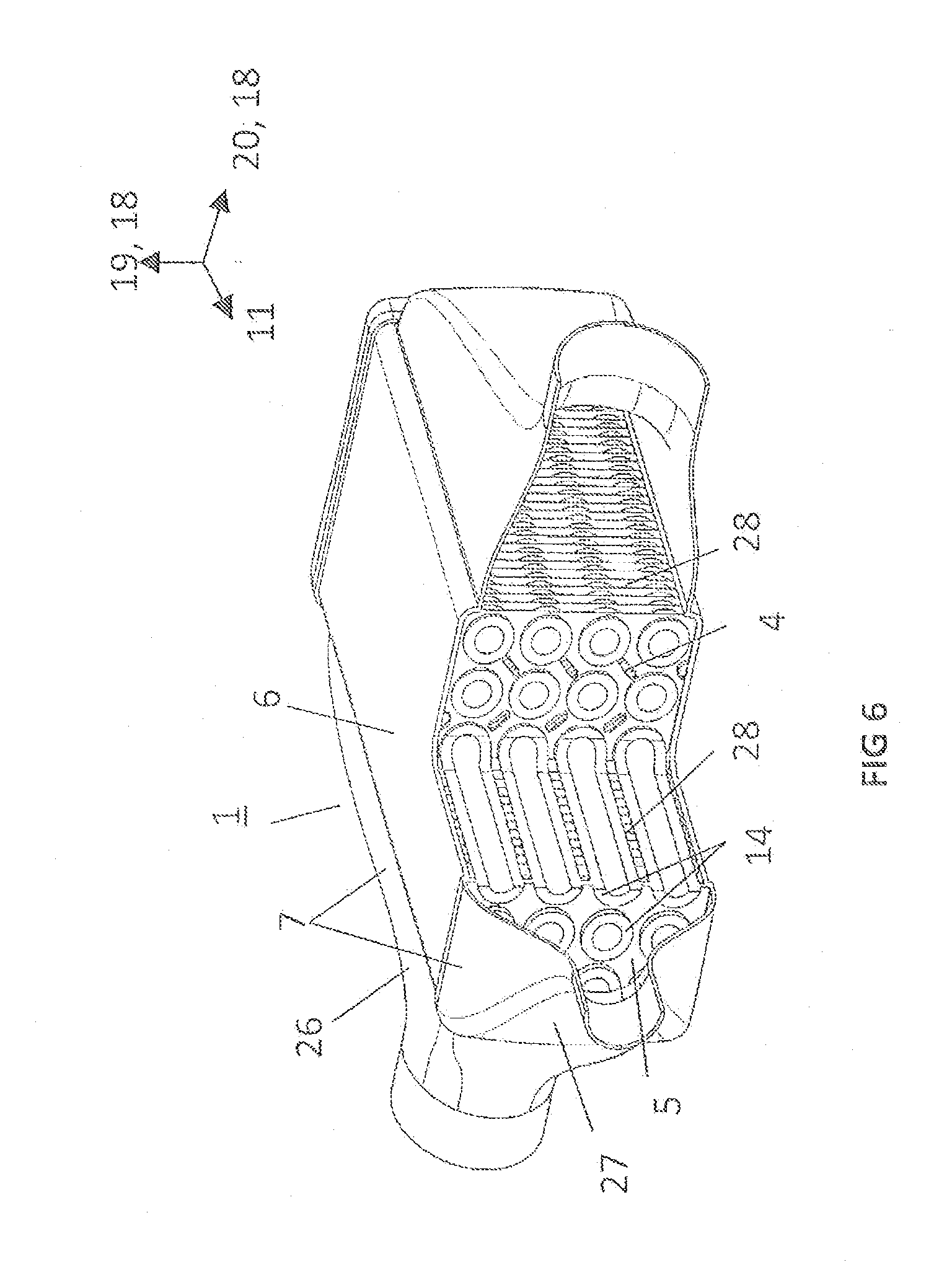
[0026] FIG. 6 shows an isometric representation of a longitudinal section of a heat exchanger according to another exemplary embodiment of the present invention;
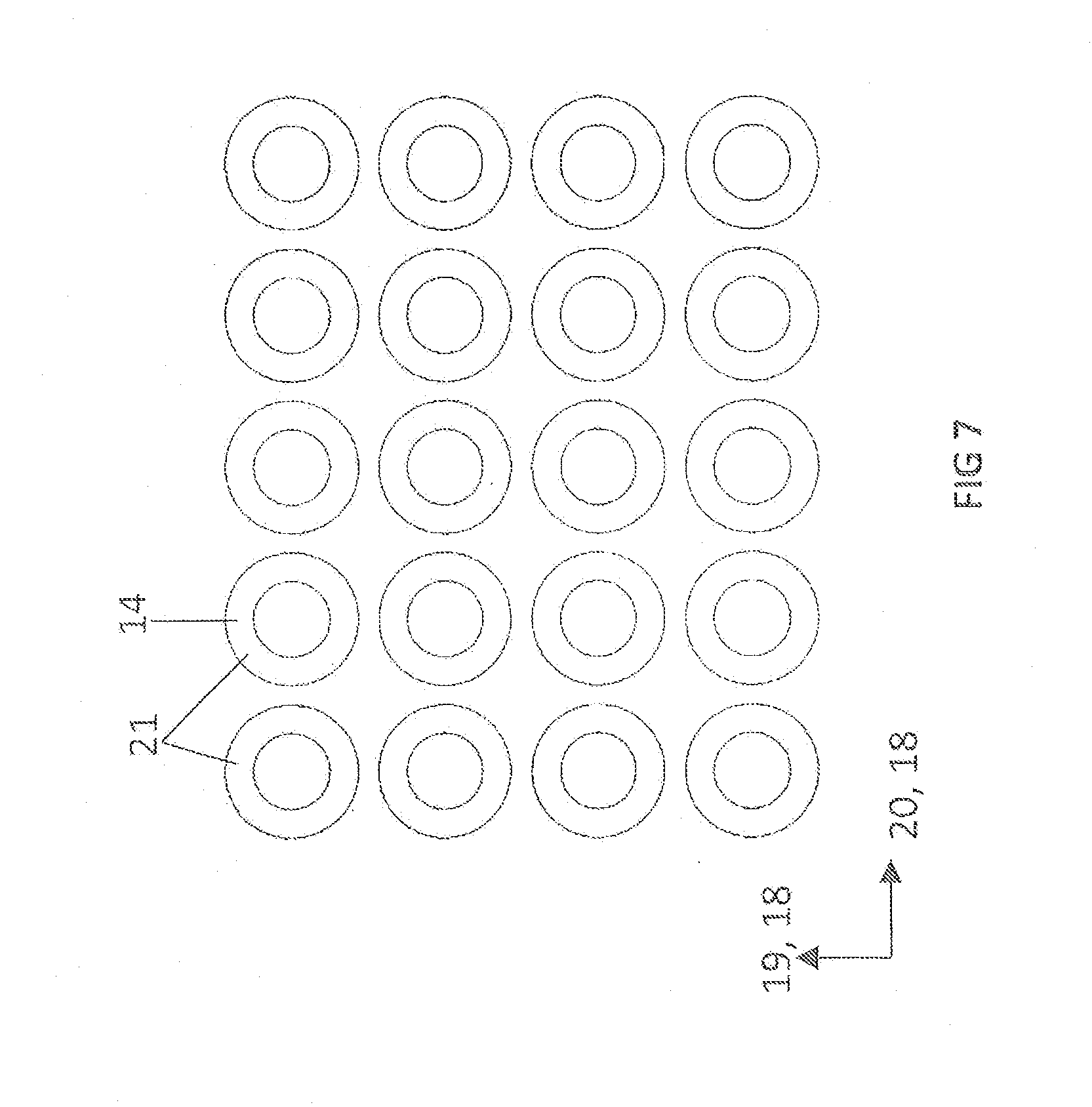
[0027] FIG. 7 shows a cross sectional view of an aligned configuration of TEM tubes according to one exemplary embodiment of the present invention;
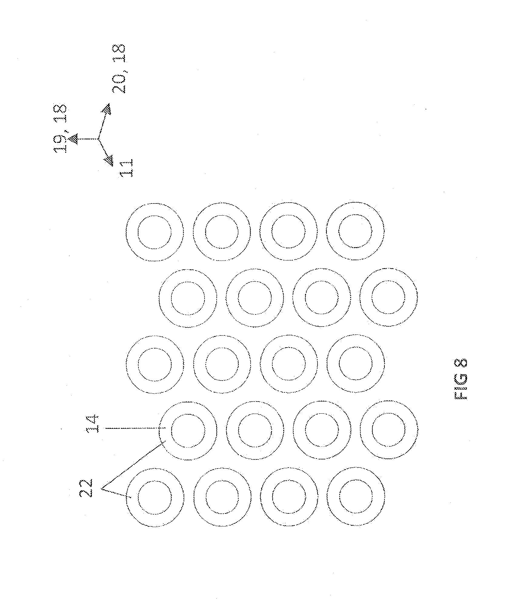
[0028] FIG. 8 shows a cross sectional view of an offset configuration of TEM tubes according to one exemplary embodiment of the present invention;
[0029] FIG. 9 shows isometric representations of two differently shaped bases for a TEG according to the invention, according to exemplary embodiments of the present invention;
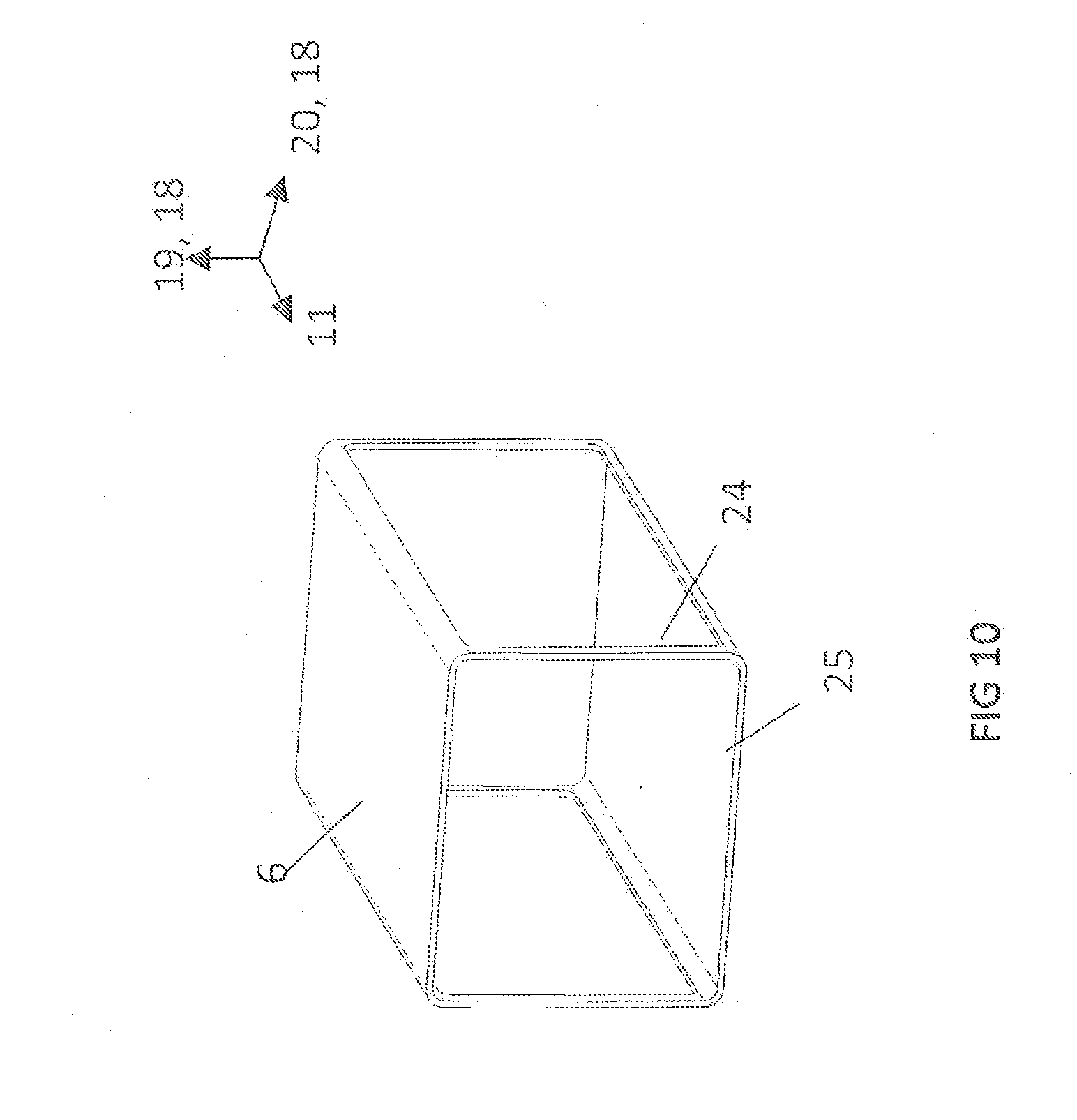
[0030] FIG. 10 shows an isometric representation of a housing for a TEG according to the invention, according to one exemplary embodiment of the present invention;
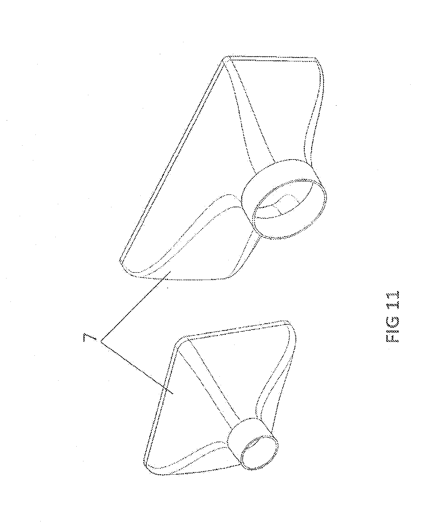
[0031] FIG. 11 shows isometric representations of two differently shaped diffusers for a TEG according to the invention, according to exemplary embodiments of the present invention;
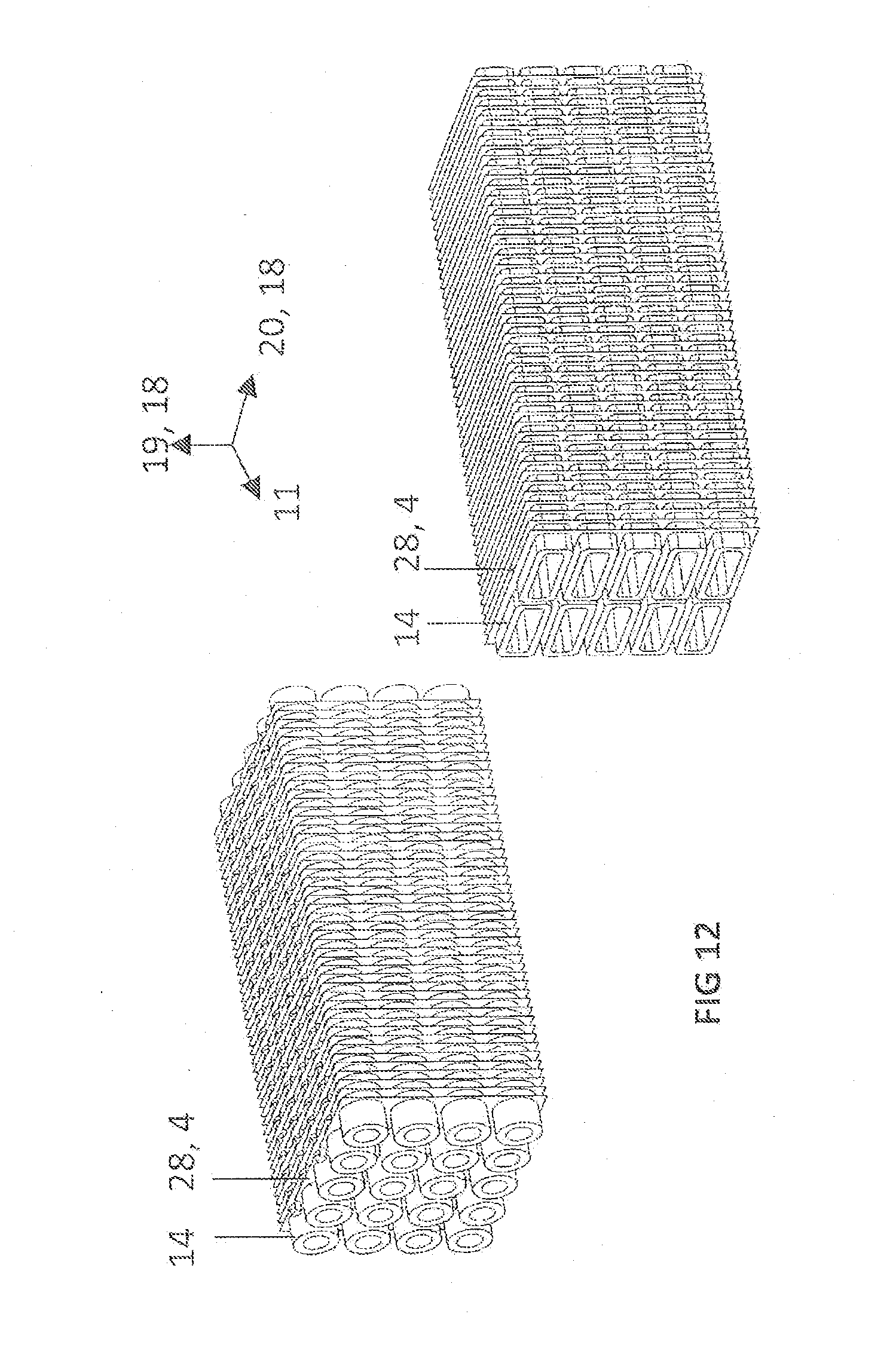
[0032] FIG. 12 shows a sectional view of isometric representations of two different embodiments of TEG blocks according to the invention which have sheet strip ribbing;
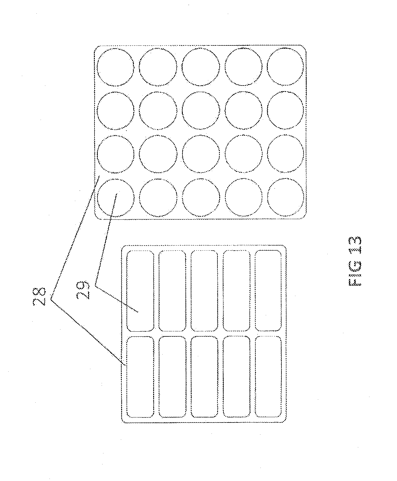
[0033] FIG. 13 shows a top view of a representation of two differently shaped sheet strips as guide sheets, according to exemplary embodiments of the present invention;
[0034] FIGS. 14 through 19 show a top view of representations of sheet strips as guide sheets which have different profiling geometries, according to exemplary embodiments of the present invention;
[0035] FIG. 20 shows a cross sectional view of a TEG having profiled sheet strips as guide sheets, according to one exemplary embodiment of the present invention;
[0036] FIG. 21 shows a sectional view of the TEG from FIG. 20, which has a schematic diagram of a flow guidance for a medium, according to one exemplary embodiment of the present invention;
[0037] FIG. 22 shows a cross sectional view of a representation of a TEG having profiled sheet strips as guide sheets, according to one exemplary embodiment of the present invention;
[0038] FIG. 23 shows the sectional view of the TEG from FIG. 22, which has a schematic diagram of a flow guidance for a medium, according to another exemplary embodiment of the present invention;
[0039] FIGS. 24 through 26 show cross sectional representations of TEGs which have different tube bundle configurations or housing geometries, according to exemplary embodiments of the present invention;
[0040] FIG. 27 shows a side view of a representation of a stack of sheet strips as guide sheets which have profiling, according to one exemplary embodiment of the present invention;
[0041] FIG. 28 shows a side view of a representation of a stack of sheet strips as guide sheets which have meshed profiling, according to one exemplary embodiment of the present invention;
[0042] FIG. 29 shows an isometric schematic diagram of a configuration of a stack of sheet strips as guide sheets having profiling, according to one exemplary embodiment of the present invention;
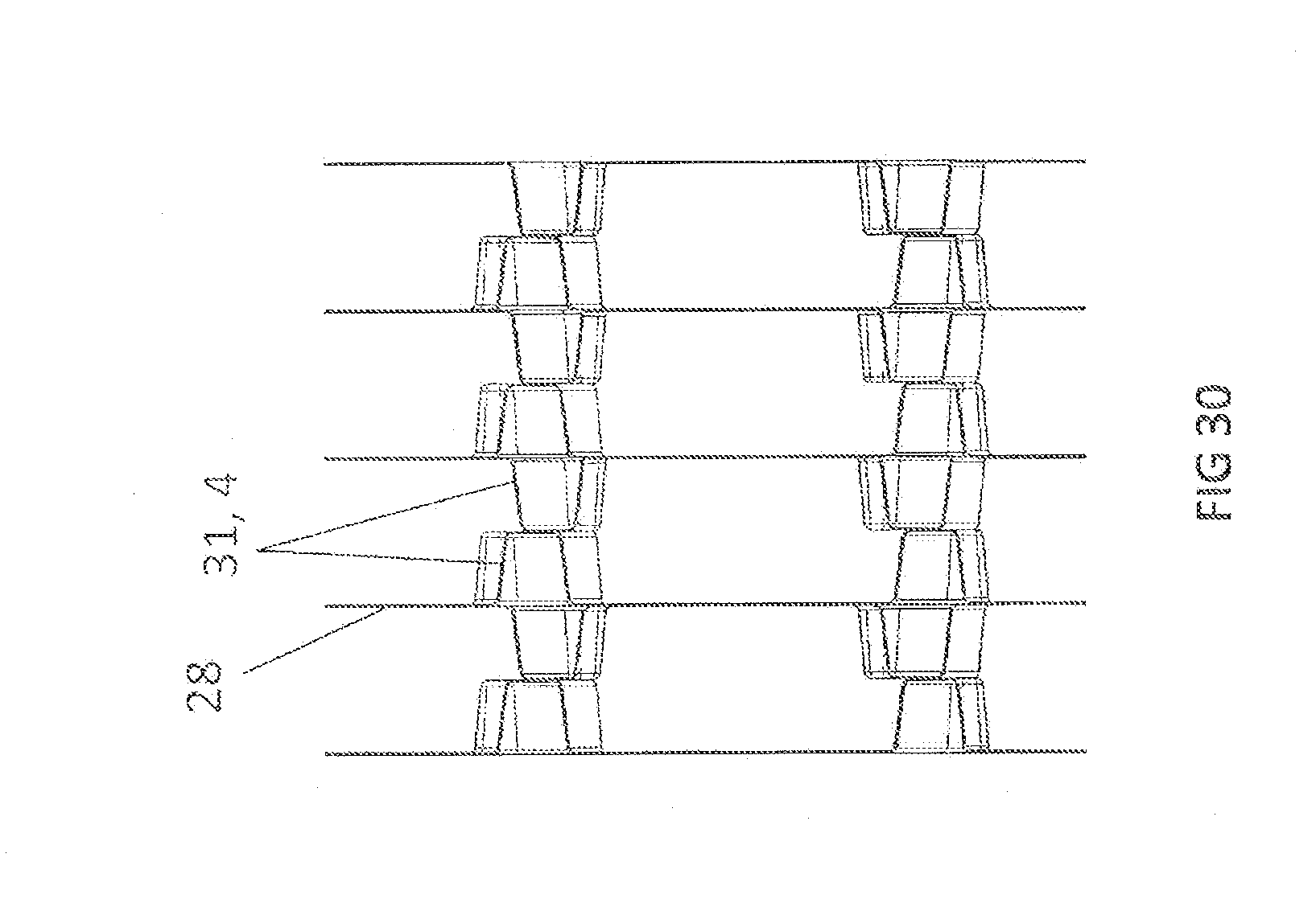
[0043] FIG. 30 shows a side view of a representation of a stack of sheet strips as guide sheets which have profiling, according to another exemplary embodiment of the present invention;
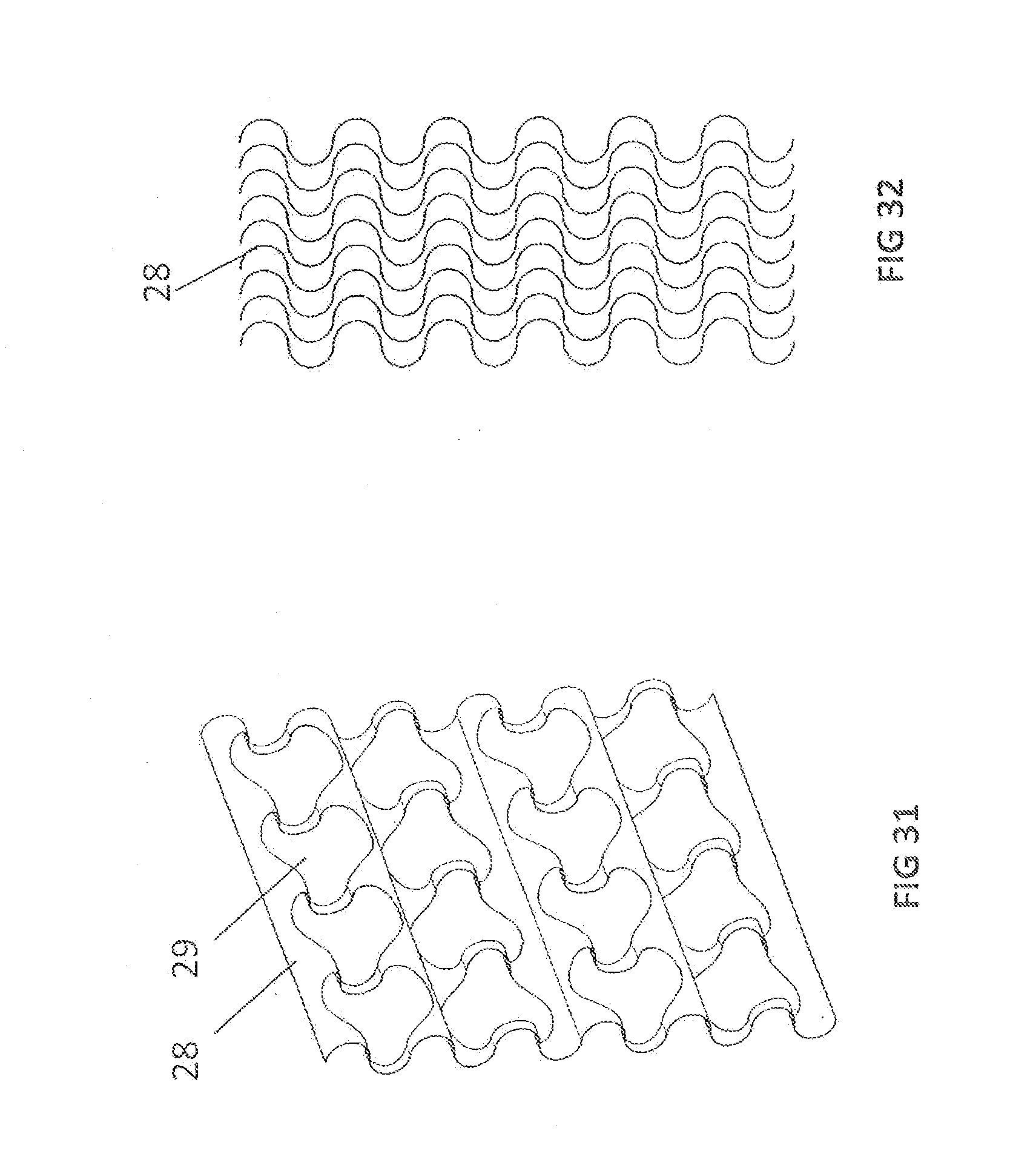
[0044] FIG. 31 shows an isometric representation of an uneven sheet strip as a guide sheet having a profiling, according to one exemplary embodiment of the present invention;
[0045] FIG. 32 shows a side view of a representation of a stack comprising a plurality of uneven sheet strips according to the exemplary embodiment from FIG. 28;
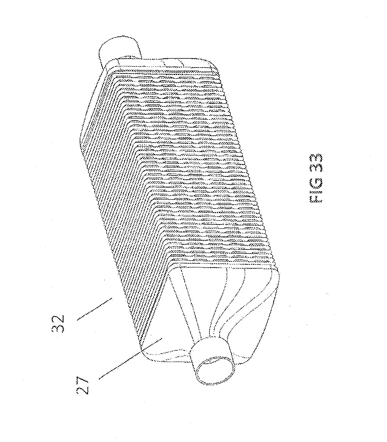
[0046] FIG. 33 shows an isometric representation of one embodiment of the heat exchanger according to the invention as a thermoelectric heater or cooler;
[0047] FIG. 34 shows an isometric representation of a longitudinal section of the thermoelectric heater or cooler according to the invention from FIG. 33;
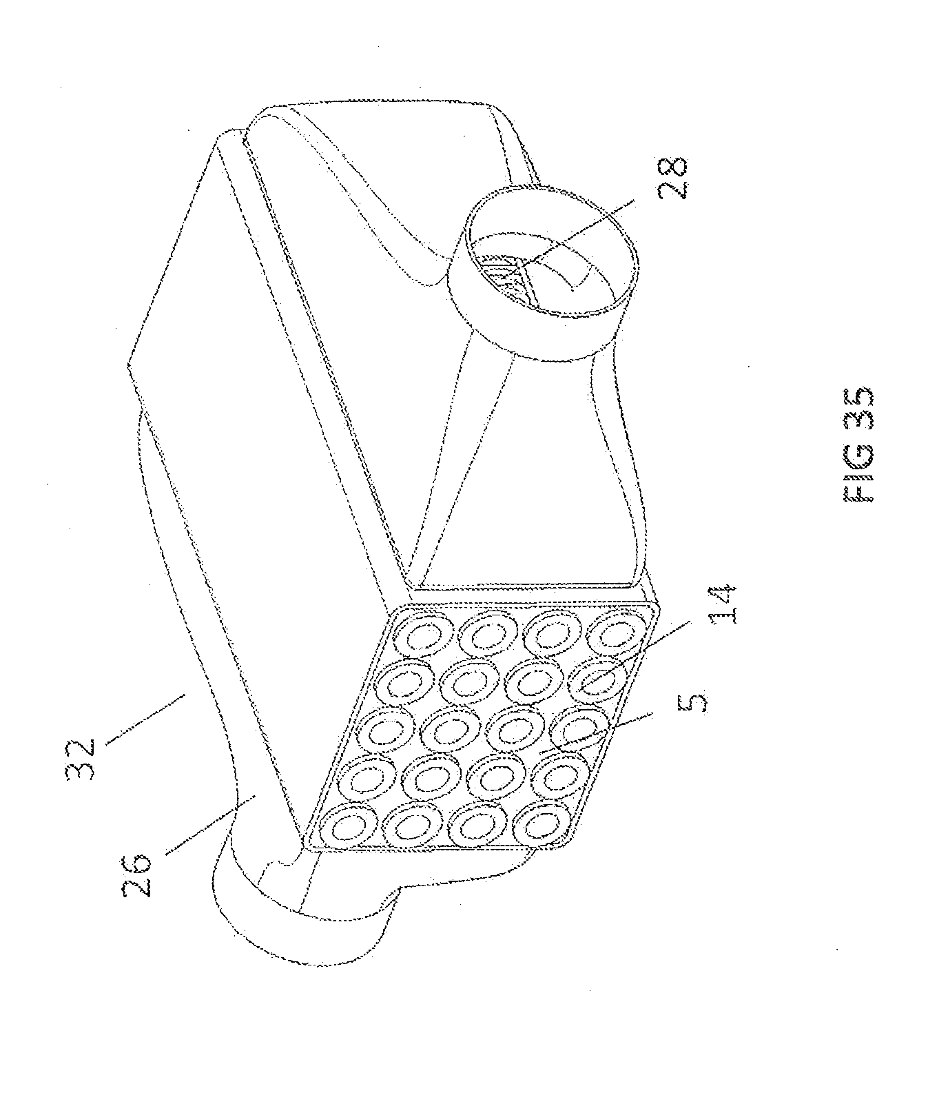
[0048] FIG. 35 shows an isometric representation of a thermoelectric heater or cooler according to another exemplary embodiment of the present invention; and
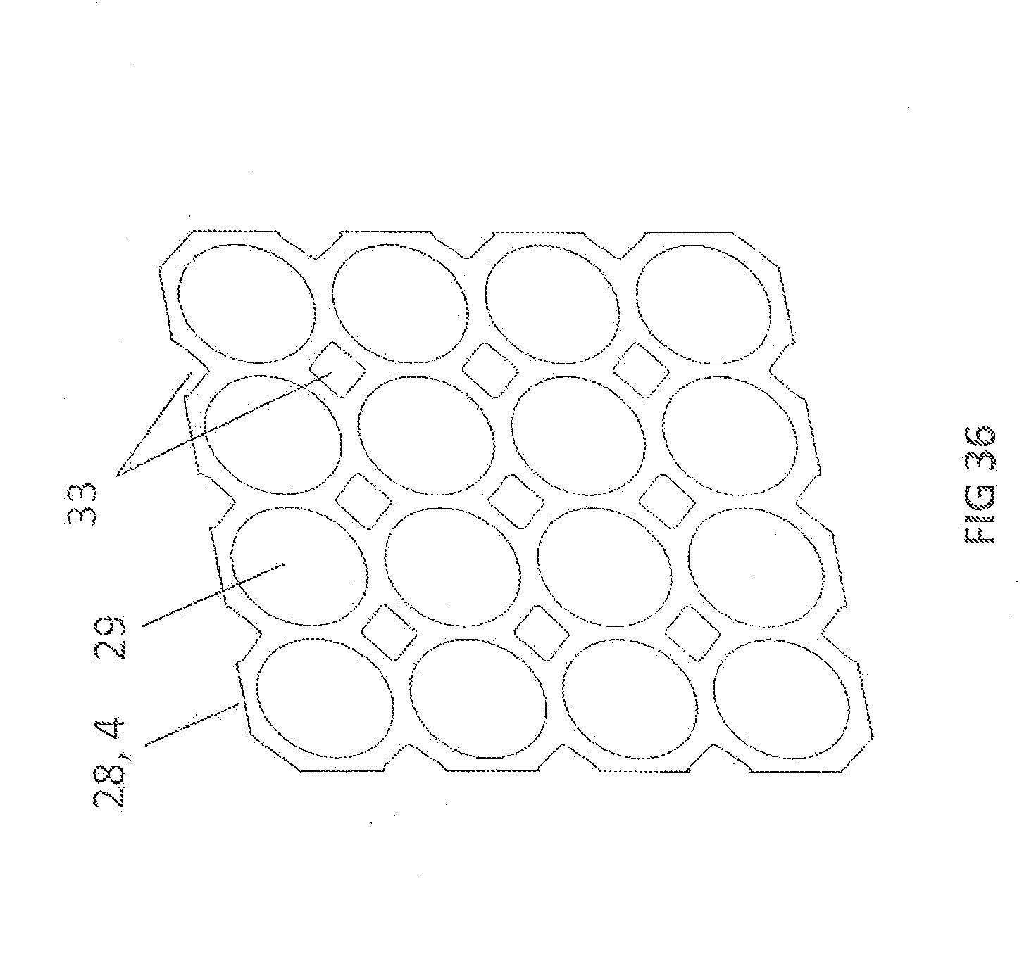
[0049] FIG. 36 shows an isometric representation of a sheet strip as a guide sheet for one embodiment of the heat exchanger according to the invention as a parallel heat exchanger, according to one exemplary embodiment of the present invention.
DETAILED DESCRIPTION
[0050] In the following description of the exemplary embodiments of the present invention, identical or similar reference numerals are used for the elements illustrated in the different drawings and having a similar function, these elements not being described repeatedly.
[0051] The heat exchanger according to the invention may be used, for example, as a thermoelectric generator (TEG) for generating electricity in a vehicle.
[0052] In a TEG according to exemplary embodiments of the invention, two media of different temperatures may be conducted past each other in a cross flow along a heat transfer route, so that heat may be transferred from the warm medium to the cold medium. The two media are separated to prevent mixing from occurring. The hot medium is, for example, exhaust gas, and the cold medium is, for example, a water/Glysantin mixture, which may be used as a coolant. The exhaust gas comes from, for example, an internal combustion engine; the water/Glysantin mixture comes from a coolant circuit for cooling different engine, air-conditioning or battery components.
[0053] The TEG may largely comprise, for example, the following components: a possible holder, a thermoelectric module (TEM), at least one profiling, at least one base, a housing, diffusers or collectors as well as a possible turbulence insert.
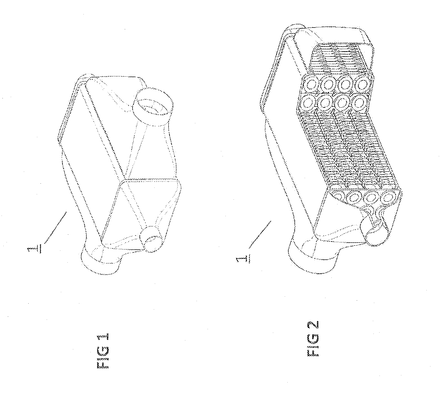
[0054] FIG. 1 shows an isometric representation of an external view of a heat exchanger 1 as a TEG according to one exemplary embodiment of the present invention.
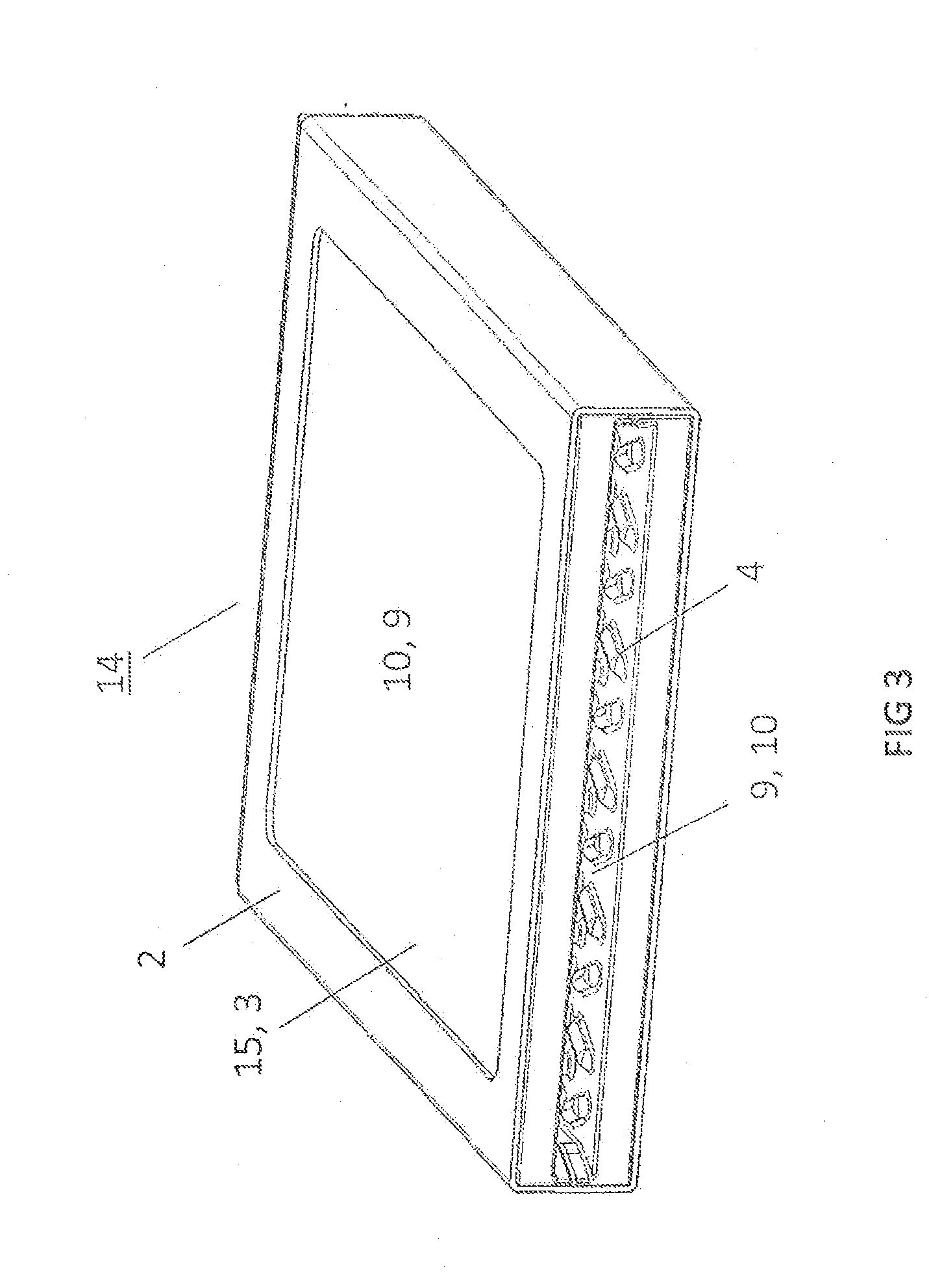
[0055] FIG. 2 shows an exemplary embodiment of an axial longitudinal section of TEG 1 according to the invention from FIG. 1. From a constructive, thermodynamic perspective, its design represents a cross-current tube bundle heat exchanger 1, through which two media of different temperatures may flow without the media mixing with each other.
[0056] According to the approach presented herein, a thermoelectric material, which forms the thermoelectric module (TEM) of the heat exchanger, is disposed on an inside of the plurality of tubes of the heat exchanger. If the heat exchanger is used as a TEG, the TEM is used to generate electricity from exhaust gas heat.
[0057] In the TEM illustrated herein, for example, a heat source based on a second medium is located on one side, and a heat sink based on a first medium is located on the other side, so that heat is transported from the warm side to the cold side due to the different temperatures of the two media. As a result the TEM produces electricity in the presence of the temperature difference according to the Seebeck effect.
[0058] The TEM is generally designed in such a way that a plurality of thermoelectrically active materials, e.g., n-doped and p-doped semiconductors, are alternately connected to each other via electric conductors. The geometric orientation of the thermoelectrically active materials is in the direction of the heat flow from the warm side to the cold side. For example, PbTe, BiTe, SiFe, SiMn or SiMg may be used as the material of the thermoelectrically active materials.
[0059] The separating plane or surface between the hot and cold sides favorable represent the TEM. This means that one side of the TEM is in direct or indirect contact with a hot source, and the other side is in direct or indirect contact with a cold area. The temperature difference provided hereby between the one side and the other side of the TEM produces thermal diffusion flows within the thermoelectrically active (TE-active) materials in the TEM, which results in an electric voltage. This phenomenon is known as the Seebeck effect. TE-active materials may be, for example, semiconductor materials. The electric voltage may be tapped in the form of electric current. For this purpose, the electric current is supplied to an electric load or an electric storage unit outside the TEM via electric lines which lead to the TEM and are connected thereto.
[0060] The TE-active materials do not touch each other, for which reason a space is provided between the TE-active materials. For efficiency reasons, a ratio between a volume of TE-active materials and a volume of space should, in principle, be as high as possible.
[0061] To set the desired electric voltages and current flows, the semiconductor conductor material integrated into the TEM may be connected in alignment or in parallel. This also applies to the electric interconnection of multiple TEMs.
[0062] The TEM or TEG construction may be executed in such a way that the TEM is designed to be media-tight. As a result, neither the first medium nor the second medium enters the interior of the TEM and thus reaches the TE-active materials.
[0063] During the course of the following description, the term "TEM tubes" is used for the tubes of the heat exchanger presented herein.
[0064] With regard to its inner and outer shape, the TEM or the TEM tube may have different designs.
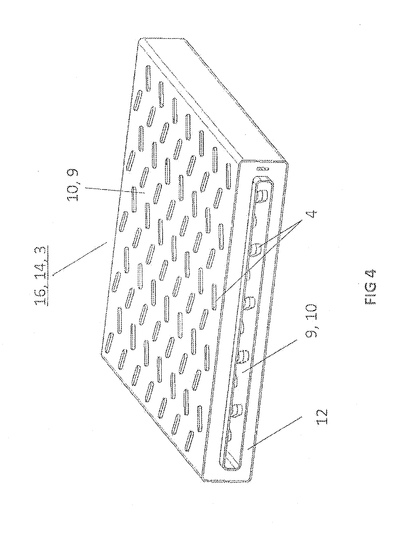
[0065] Accordingly, FIGS. 3 through 5 show isometric representations of differently designed TEM tubes, according to exemplary embodiments of the present invention.
[0066] FIG. 3 shows an isometric representation of a planar TEM tube 14. The planar TEM tube comprises a rectangular tube 2 as well as two thermoelectric modules 3. According to this exemplary embodiment, rectangular tube 2 is designed as a holder which has recesses on its opposite main sides. TEMs 3 in this case are designed as planar TEMs 15 and are accommodated in holder 2 and connected media-tight thereto. TEMs 15 are disposed parallel to each other. One of the first and second media 9, 10 flows within holder 2, and thus between TEMs 15, and the other of the first and second media 10, 9 flows outside holder 2. TEMs 15 are exposed directly to the two media 9, 10. At lest one surface of each of the two TEMs 15 has a profiling 4 on facing sides of TEMs 15. Holder 2 and TEMs 15 separate media flows 9, 10. Holder 2 and TEMs 3, 15 form a unit which resembles a flat tube and are referred to in combination as TEM tube 14.
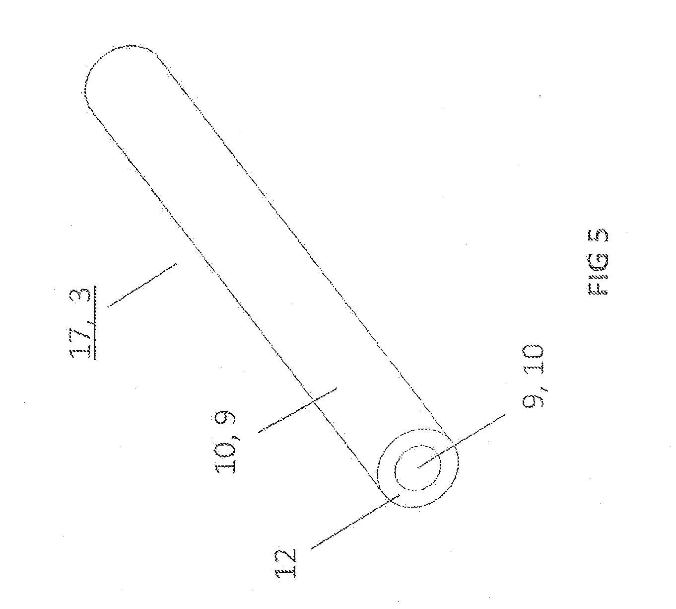
[0067] FIG. 4 shows another example of a method for forming TEM tube 14 in an isometric representation. TEM tube 14 according to the invention is formed by a double-walled rectangular tube 16, TE-active materials 12 being introduced into the space between the two walls as thermoelectric module 3. The inner wall of the two walls of TEM tube 16 is in contact with one of the two media 9, 10, while the outer wall of the two walls of TEM tube 16 is in contact with the other of the two media 9, 10. For example, the inner wall of the two walls of TEM tube 16 may contact first medium 9, and the outer wall of the two walls of TEM tube 16 may contact second medium 10. First medium 9 may be a coolant from a coolant circuit of the vehicle, and second medium 10 may be an exhaust gas of an internal combustion engine of the vehicle. In the exemplary embodiment illustrated in FIG. 4, the particular media-side surfaces of the inner and outer walls of rectangular tube 16 have a profiling 4.
[0068] FIG. 5 shows an isometric representation of a TEM tube in the form of a round tube TEM 7. The TEM tube is formed by a double-walled round tube 17, TE-active materials 12 being introduced into the space between the two walls as TEM 3. The inner wall of the two walls of TEM tube 17 is in contact with one of the two media 9, 10, while the outer wall of the two walls of TEM tube 17 is in contact with the other medium 9, 10. For example, the inner wall of the two walls of TEM tube 17 may contact first medium 9, and the outer wall of the two walls of TEM tube 17 may contact second medium 10. First medium 9 may be a coolant from a coolant circuit of the vehicle, and second medium 10 may be an exhaust gas of an internal combustion engine of the vehicle.
[0069] FIG. 6 shows an isometric representation of a construction of TEG 1 in a longitudinal sectional view, according to another exemplary embodiment of the present invention. A profiling 4, a base 5, a housing 6, TEM tubes 14, a radial diffuser 7, 26, an axial diffuser 7, 27 and a guide sheet or sheet strips 28 are illustrated. An arrow system 11; 19, 18; 20, 18 identifies the three dimensions of the space to illustrate the isometric representation. Viewed from the perspective of an observer of the representation, 11 represents an axial direction, 18 a radial direction, 19 a vertical direction and 20 a horizontal direction. In the paragraphs below, FIGS. 7, 8, 10, 12, 24, 25 and 26 provide corresponding dimension identifiers.
[0070] In the exemplary embodiment illustrated in FIG. 6, TEM tubes 14 in TEG 1 are disposed one on top of the other, according to dimension 18, 19, and/or adjacent to each other, according to dimension 18, 20, similarly to a tube bundle, and they do not touch each other. One of the two media 9, 10 flows within TEM tubes 14, while the other medium flows outside TEM tubes 14 and thus between the individual layers and columns of TEM tubes 14. The TEMs are disposed in TEM tubes 14. TEM tubes 14 may have a profiling or ribbing 4 both on the inside and on the outside to increase the heat transfer. However, this is not illustrated in FIG. 6. Furthermore, a turbulence insert, which is also not illustrated in FIG. 6, may also be provided to increase the heat transfer. FIG. 6 shows a profiling 4 of guide sheets 28 in the form of elongated raised structures or knobs 4. In the interest of clarity, only one of the raised structures or knobs 4 on one of sheet strips 28 is provided with a reference numeral herein.
[0071] Both the first medium and the second medium may be guided on both the inside and the outside of TEM tubes 14. The first and second media are not in direct contact with each other, and they do not mix with each other. As a result, TEM tubes 14 separate the two media streams of the first and second media along a heat transfer route, i.e., in radial direction 18. A length of TEM tubes 14 in axial direction 11 corresponds to the heat transfer route in TEG 1. A beginning and an end of TEM tubes 14 represent the inlet and outlet of the first or second medium on the heat transfer route within TEM tube 14.
[0072] TEG 1 according to the invention my have four diffusers 7, via which TEG 1 may communicate with connections on the gas and coolant sides. For example, a first radial diffuser 26 acts as an inlet for exhaust gas, another radial diffuser 26 opposite the first radial diffuser acts as an outlet for the exhaust gas, a first axial diffuser 27 acts as an inlet for a coolant, and another axial diffuser 27 opposite the first axial diffuser acts as an outlet for the coolant.
[0073] FIG. 7 shows a cross sectional view of an aligned configuration 21 of TEM tubes 14 according to one exemplary embodiment of the present invention. Any number of TEM tubes 14 may be layered one on top of the other, i.e., in vertical direction 19. Any number of TEM tubes 14 may also be disposed adjacent to each other, i.e., in horizontal direction 20. In aligned configuration 21 of TEM tubes 14, a passage between the particular rows of TEM tubes 14 is located in both vertical direction 19 and horizontal direction 20.
[0074] FIG. 8 shows a cross sectional view of an offset configuration 22 of TEM tubes 14 according to another exemplary embodiment of the present invention. In adjacent vertical rows of TEM tubes 14, it is apparent that one tube 14 from one row is always disposed upstream from a passage between two tubes in an adjacent row.
[0075] Knob-like, protruding structures, which ensure mutual support of TEM tubes 14 against each other, may be embossed into surfaces of TEM tubes 14 illustrated in FIGS. 7 and 8. A contact between TEM tubes 14 may thus be provided at these points. However, structures of this type are not illustrated in FIGS. 7 and 8.
[0076] The individual TEM tubes of the TEG are connected to each other in their particular longitudinal axial end areas by means of bases 5.
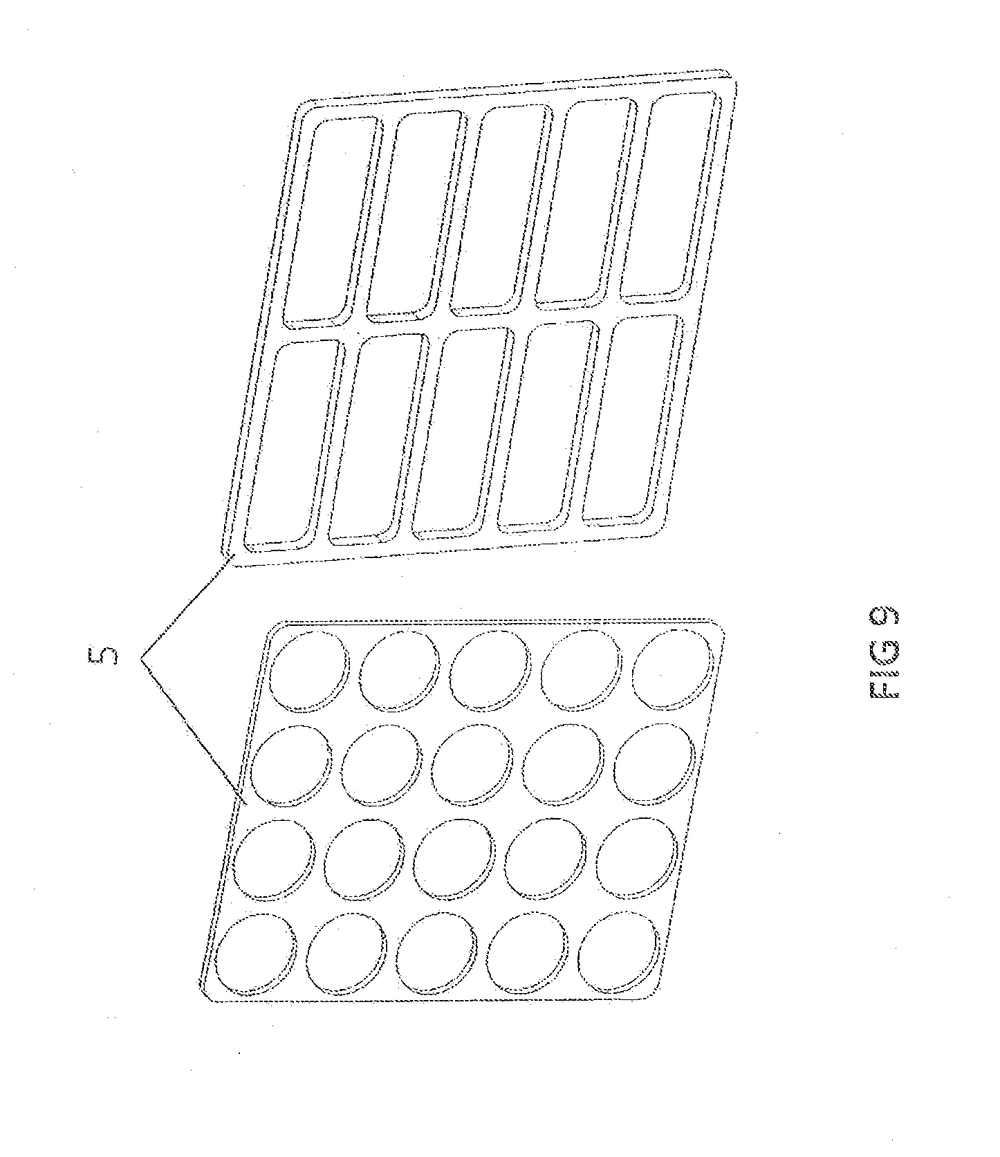
[0077] FIG. 9 shows an isometric representation of a base 5 for a TEG having round TEM tubes as well as an isometric representation of a base 5 for a TEG having rectangular TEM tubes, according to exemplary embodiments of the present invention.
[0078] Base 5 separates the media flows of the first medium and the second medium at the end faces of the heat transfer route, i.e., at its inlet and outlet, and thus in the axial direction. Base 5 is a deformed metal sheet which is manufactured, for example, from high grade steel. It is provided with a plurality of recesses, the number, configuration and shape of which correspond to the TEM tubes, which may be connected to the recesses in base 5. The connection may be carried out, for example, by laser welding. For this purpose, the tubes may be first inserted into the recesses in base 5. In general, one base 5 is joined to one inlet and outlet of the tube bundle. The recesses and the circumferential outer contour of base 5 may be provided with passages.
[0079] To assemble the TEG according to the invention in a media-tight manner, the circumferential contour of the base may be connected to a housing and/or a diffuser of the TEG. Laser welding, for example, may again be used as the connecting technique in this case.
[0080] FIG. 10 shows an isometric representation of one exemplary embodiment of a housing 6 for a TEG according to the invention.
[0081] With regard to its shape, housing 6 is a round or rectangular, rounded tube. Housing 6 may be offset multiple times in axial direction 11. The first or second medium may be guided between an outer side of the TEM tubes and an inner side of housing 6 crosswise, i.e., in directions 18, 19, 20, or longitudinally, i.e., in direction 11, in relation to the TEM tubes. Housing 6 thus separates the media flow of the first medium or the second medium from the surrounding atmosphere in radial direction 18 along the heat transfer route. A collection of this media flow upstream and downstream from housing 6 is therefore not necessary.
[0082] Housing 6 is provided with an opening 24 on each of two opposite sides in the radial direction (18). This opening 24 may be provided with a passage. In FIG. 10, only one of the two radial openings 24 is provided with a reference numeral. The two openings 24 may each be connected to a connecting line or a radial diffuser. The first or second medium may be guided into or out of housing 6 via openings 24. Ends 25 of housing 6 oriented along axial direction 11 may be connected by their inside or outside to the bases and/or to two additional diffusers, e.g., by means of laser welding. The TEG may thus have two radially disposed diffusers and two axially disposed diffusers. The diffusers are not illustrated in FIG. 10 and are explained in connection with FIG. 11 below.
[0083] Another small opening may be provided in the housing through which, for example, electric lines of the TEM tubes may be run. The opening would have to be sealed with an appropriate substance, e.g., adhesive. An opening of this type is not illustrated in FIG. 10.
[0084] FIG. 11 shows two exemplary embodiments of differently shaped diffusers 7 for a TEG according to the invention. Diffusers 7 may be disposed as radial diffusers at two radially opposite ends of the housing of the TEG according to the invention or as axial diffusers at two axially opposite ends of the housing of the TEG according to the invention.
[0085] Diffuser 7 may be formed from a deformed and/or welded metal sheet. It has two openings. On the side of the first opening, diffuser 7 is connected to a power line; on the side of the second opening, it is connected to the base and/or to the housing of the TEG. The openings naturally and generally have different diameters. Diffuser 7 is provided with an advantageous flow design. The space between an inner wall of an axial diffuser and the base forms a chamber which collects the medium communicating with the TEM tubes prior to entering the tubes and after exiting the tubes. As a result, two diffusers are generally provided for each TEG in the axial direction.
[0086] FIG. 12 shows isometric representations of sectional views of two different embodiments of TEG blocks according to the invention. Both TEG blocks illustrated in FIG. 12 have a configuration of a plurality of TEM tubes 14 and a plurality of guide sheets 28, tubes 14 in the top TEG block illustrated having a round cross section, and tubes 14 in the lower TEG block illustrated having a rectangular cross section.
[0087] In the embodiments of the TEG illustrated in FIG. 12, the hot medium, e.g., the exhaust gas, is guided on the outside of TEM tubes 14, and the cold medium, e.g., the coolant, is guided on the inside of TEM tubes 14. The cold medium in TEM tubes 14 flows largely in axial direction 11, which may include a swirling flow possibly produced by turbulence inserts which are not illustrated. The hot medium flows crosswise into TEM tubes 14 on the outside thereof, i.e., in directions 18, 19, 20. The TEG is thus thermodynamically a cross flow heat exchanger.
[0088] A ribbing 28 is provided on the outside of TEM tubes 14. Thin sheet strips 28, which are stacked one on top of the other in a parallel configuration or layered in axial direction 11 are provided as guide sheets, which are penetrated by the bundle of TEM tubes 14 orthogonally to sheets 28. For this purpose, each sheet strip 28 has recesses whose shape matches the outer contour of TEM tubes 14. In cross section, these sheet strips may have a round as well as rectangular shape or a shape which deviates therefrom. Sheet strips 28 may be provided with a profiling 4.
[0089] FIG. 13 shows a guide sheet 28 for a plurality of rectangular TEM tubes as well as a guide sheet 28 for a plurality of round TEM tubes, each in a top view, according to exemplary embodiments of the present invention.
[0090] Recesses 29 in sheet strips 28 may have passages or indentations and/or introduction angles which facilitate the joining of sheet strips 28 with the TEM tubes or which may ensure a connection between sheet strips 28 and the TEM tubes over a wider area. The heat transfer resistance may be reduced in this manner. The passages or indentations or insertion angles are not illustrated in FIG. 13. Another function of recesses 29 may be to hold and position the TEM tubes along the heat transfer route. In FIG. 13, only one recess 29 is provided with a reference numeral in the two exemplary embodiments of guide sheet 28.
[0091] For example, the connection between a recess 29 and a TEM tube or a passage of a recess and a TEM tube is a press fit, it being possible to deform recess 29 or the recess having passage 30 during the joining of sheet 28 to the TEM tube. The connection may therefore be a force-fit or form-locked connection and thus represent a mechanical connection. Alternatively or additionally, the connection may also be an integral connection, which may be produced, for example by soldering. The passages enlarge the contact surfaces on the TEM tube and may be used as spacers for sheet strips 28. Adjacent sheet strips 28 then touch each other at these points.
[0092] In the TEG, the sheet strips are generally spaced a distance apart. The hot medium, for example, flows between the sheet strips. The axial distance between the sheet strips may be 1-6 mm according to the invention and preferably 2-4.5 mm. A shorter distance could cause the pressure drop to increase disproportionately due to fouling, e.g., due to soot and particle deposits. A greater distance, in turn, could have the disadvantage that the heat transfer and the transfer surfaces are reduced, which could result in a lower capacity.
[0093] To permit or improve a spacing between the sheet strips, these sheet strips may have indentations, bent notches and/or latching tabs which are used to space the sheet strips a distance apart. Adjacent sheet strips then touch each other at these points.
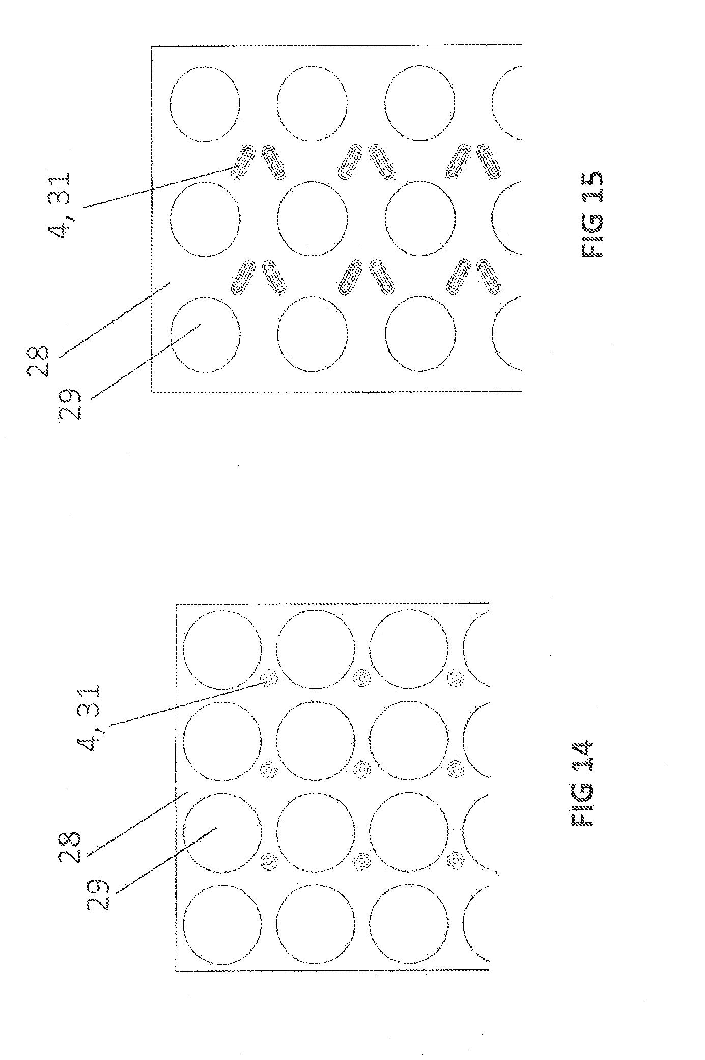
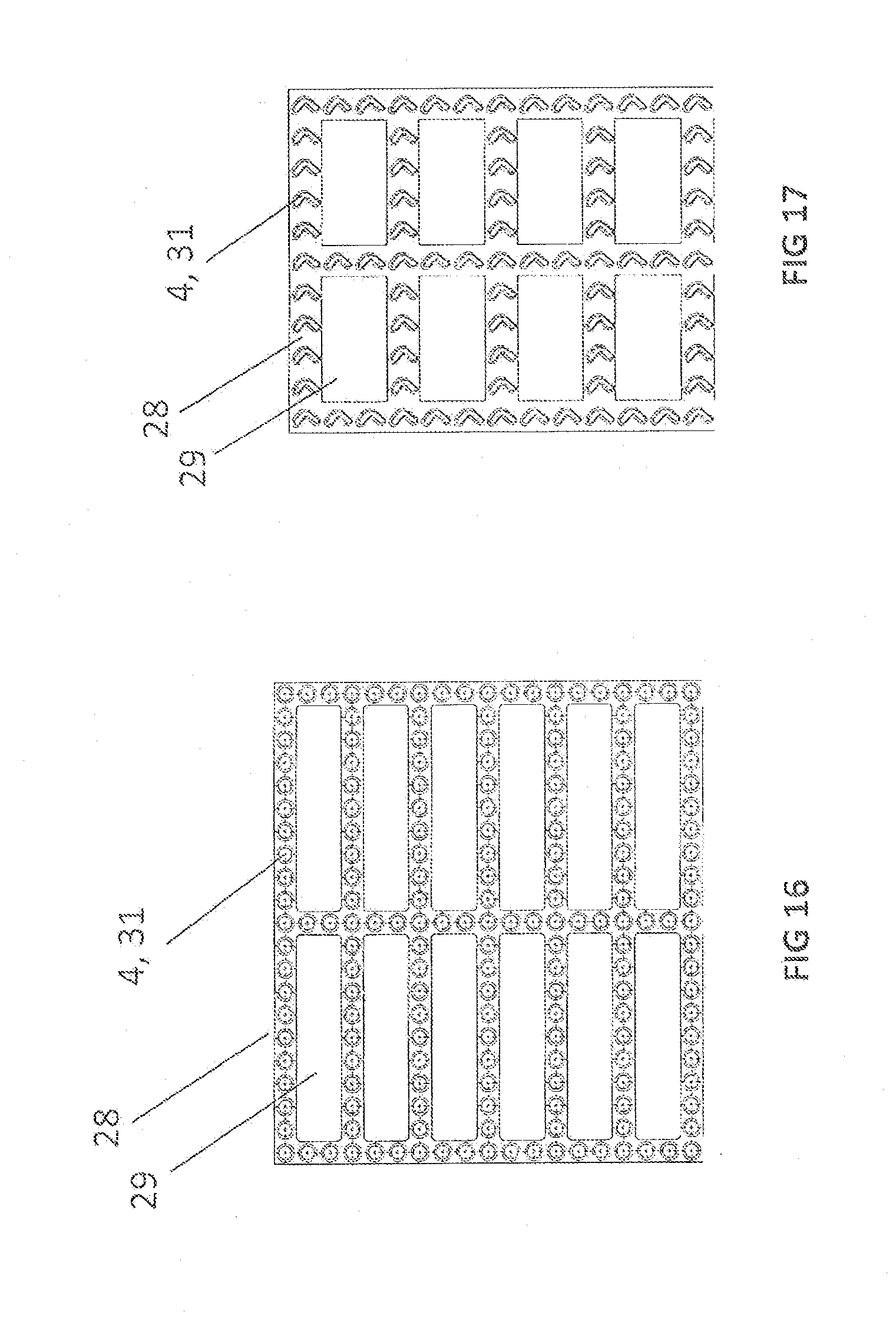
[0094] FIGS. 14 through 19 show top views of corresponding exemplary embodiments of sheet strips 28 having recesses 29 for round or rectangular tubes and different profilings 4.
[0095] Sheet strips 28 may have surface-increasing and heat transfer-increasing profilings 4 or embossed areas 4 and/or stamped areas 4 and/or notches 4 such as winglets 4 and/or knobs 4 and/or ribs 4 and/or gills 4, which may be used as spacers 31 for sheet strips 28. FIG. 14 shows round spacers (notches) in combination with round openings/recesses 29, while FIG. 15 shows elongated spacers 4, 31 in combination with round openings 29, elongated spacers 4, 31 forming a flow surface for guiding the second medium. FIG. 16 shows round knobs 4, 31 in combination with recesses 29 for rectangular flat tubes, a combination of winglet-shaped profiling elements 4, 31 in combination with recesses 29 for rectangular flat tubes being illustrated in FIG. 17. FIG. 18 shows a representation having a combination of recesses 29 for round tubes which have elongated profiling elements 4, 31, while FIG. 19 shows a representation of a combination of recesses 29 for round tubes which have round profiling elements 4, 31 on the edge of the guide sheet and elongated profiling elements 4, 31 between diagonally disposed recesses for round tubes.
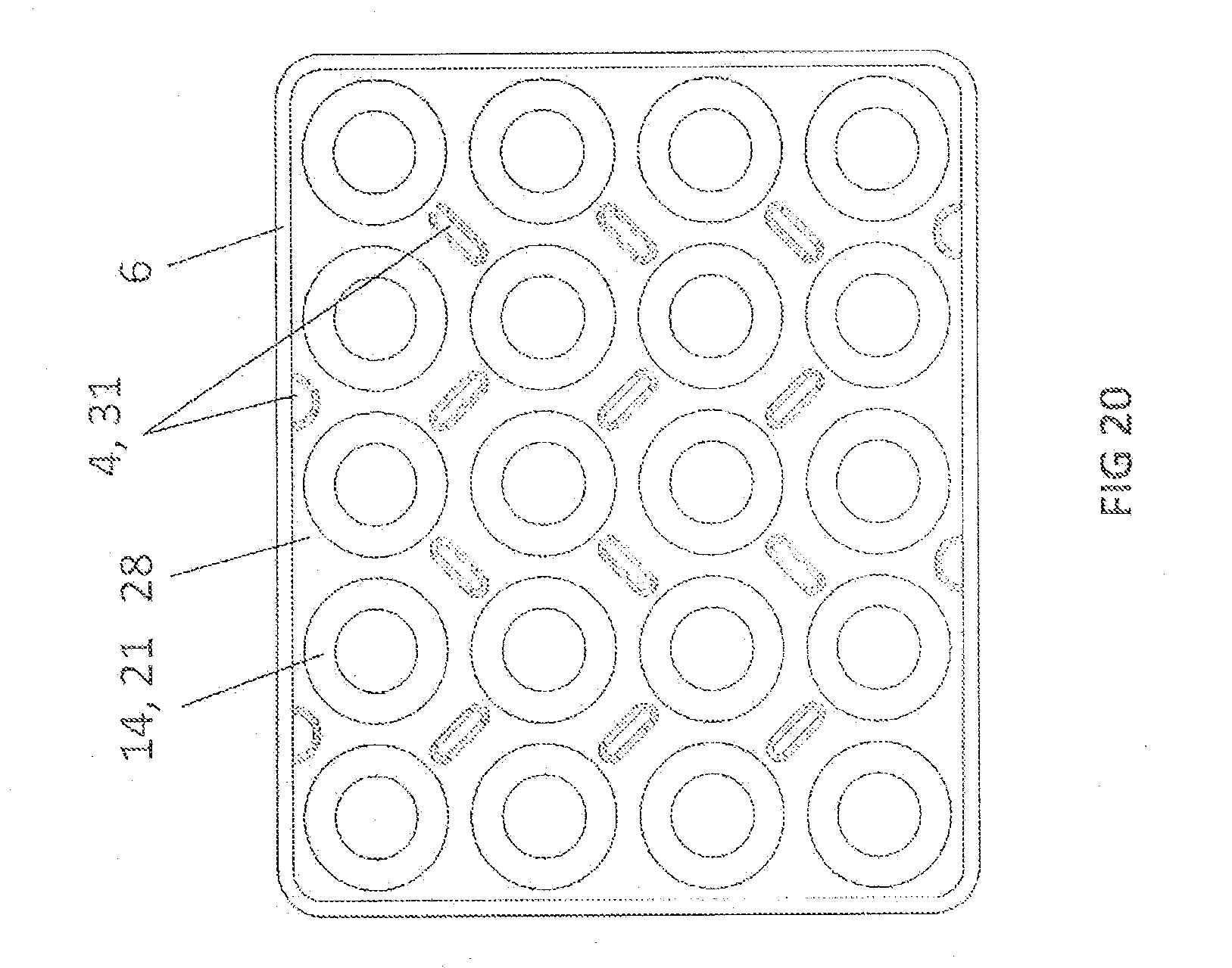
[0096] FIG. 20 shows a cross sectional representation of a TEG according to the invention, according to one exemplary embodiment of the present invention. Housing 6, a guide sheet 28 having profiling 4 as spacers 31 as well as aligned configuration 21 of TEM tubes 14 are illustrated.
[0097] According to one exemplary embodiment of the invention, profilings 4 of sheet strips 28 are not only used to enlarge the heat transfer surface and to interrupt the laminar limiting layer in the flow and/or to produce swirls in the flow, which may be used to increase the capacity of the TEG. Profilings are also used to advantageously guide and/or deflect the flow, for example of the second medium. This may be necessary, in particular, when the bundle of TEM tubes 14 have a relatively high packing density for reasons of installation space. In this case, TEM tubes 14 follow each other very closely in dimensions 18, 19, 20, whereby the unwanted production of still water zones between two adjacent or two consecutive TEM tubes 14 may be avoided. This is the case, in particular, when the hot media flow is able to flow unhindered in radial direction 18 if TEM tubes 14 are disposed in aligned configuration 21. To prevent this, profilings 4 are disposed according to the invention as shown in FIG. 20.
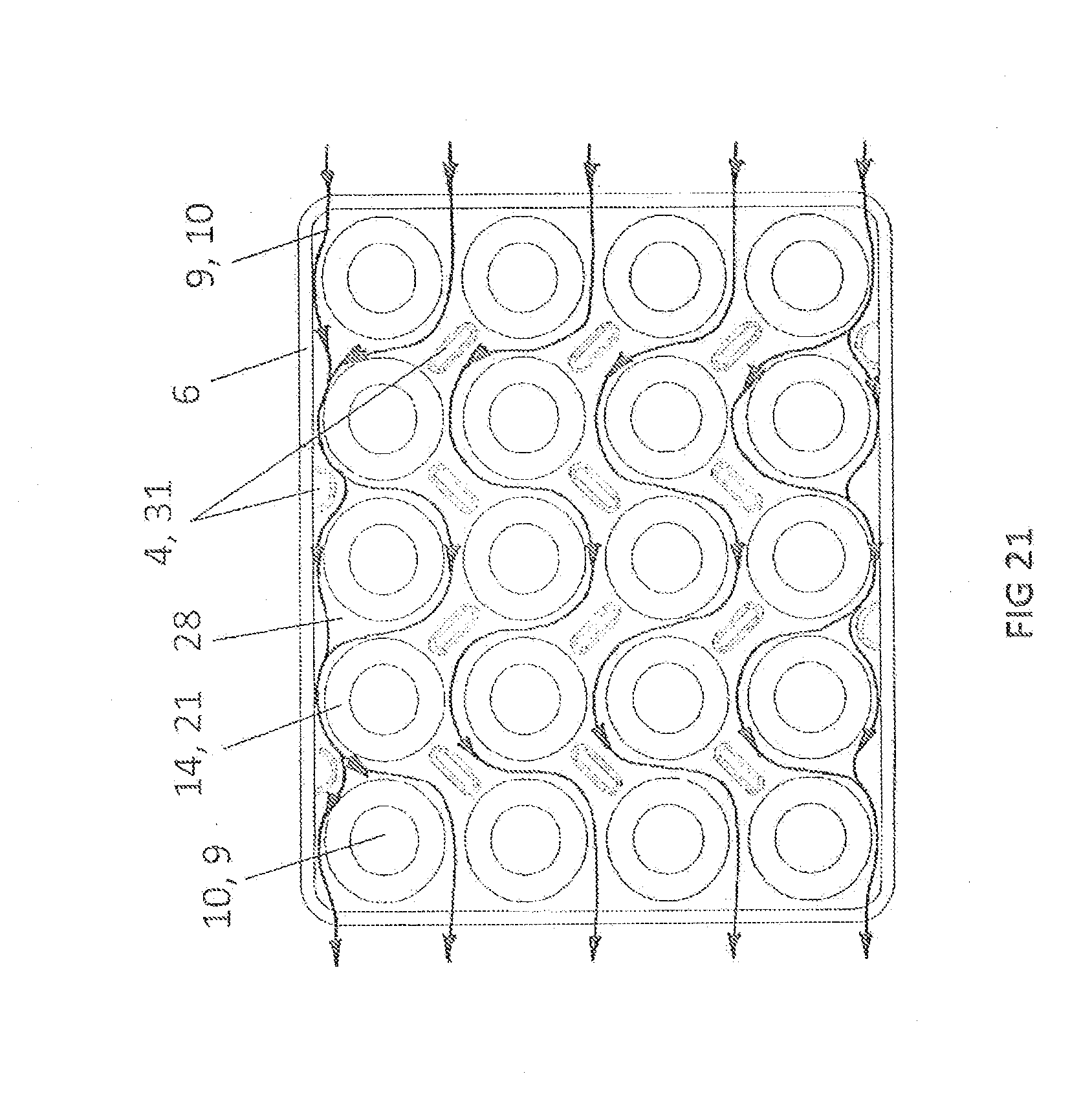
[0098] FIG. 21 shows the sectional view of the TEG according to the invention from FIG. 20, to which a flow guidance for one of first and second media 9, 10 is added, the other one of first and second media 10, 9 being guided in TEM tubes 14. FIG. 21 clearly shows that the flow guidance results from the configuration of profiling 4 or spacers 31 (notches) in relation to aligned configuration 21.
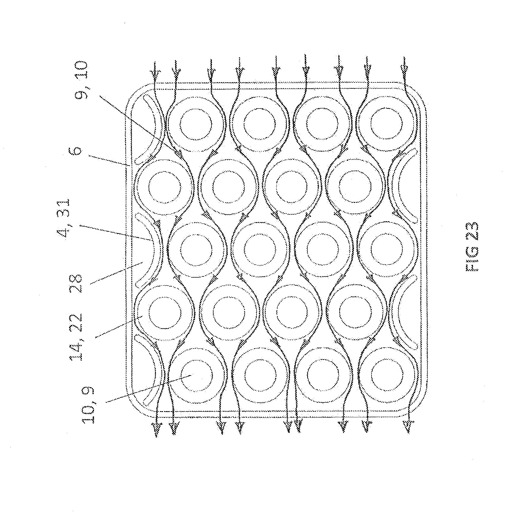
[0099] FIG. 22 shows a cross sectional view of a TEG according to the invention, according to one exemplary embodiment of the present invention. The figure shows housing 6, a guide sheet 28 having profiling 4 on the edge of the guide sheet as a spacer 31 and as a guide element for guiding the second medium to a recessed tube. The representation in FIG. 22 also shows offset configuration 22 of TEM tubes 14.
[0100] FIG. 23 shows the sectional view of the TEG according to the invention from FIG. 22, to which a meandering flow guidance for one of first and second media 9, 10 is added, the other one of first and second media 10, 9 being guided in TEM tubes 14.
[0101] It is apparent from FIGS. 22 and 23 that a profiling 4 for advantageous control of media flow 9, 10 may be dispensed with up to an edge area of guide sheet 28. If TEM tubes 14 are namely disposed in an offset configuration 22 along hot, radial media flow 18, housing geometry 6 not being adapted to the bundle of TEM tubes 14, profiling 4 in this case may also be used to advantageously generate similar flow gaps in the entire external area of TEM tubes 14, so that a favorable, uniform distribution of mass flow density, i.e., the local mass flow, may be achieved. This embodiment is suitable, in particular, when housing geometry 6 is not specially adapted to offset TEM tubes 14.
[0102] As explained in connection with FIGS. 20 through 23, TEM tubes 14 may thus be disposed in an aligned configuration 21 or offset configuration 22 along hot, radial 18 media flow 9.
[0103] For example, housing geometry 6 may be adapted to the bundle of TEM tubes 14, viewed over the cross section, so that similar flow gaps advantageously prevail in the entire external area of TEM tubes 14, in particular in width direction 19, so that a favorable, uniform distribution of the mass flow density may be achieved.
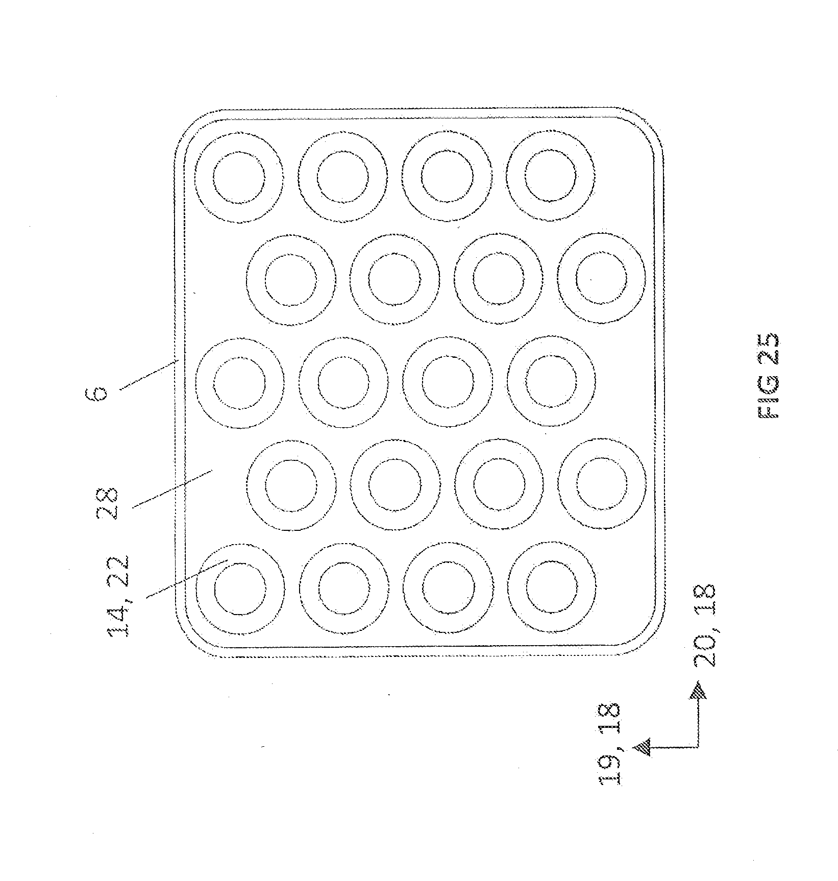
[0104] FIGS. 24 through 26 show cross-sectional representations of exemplary embodiments of housing geometries 6 of the TEG according to the invention with reference to an aligned or offset configuration of TEM tubes 14.
[0105] An adaptation of housing geometry 6, or a special type of adaptation of housing geometry 6, to the configuration of TEM tubes 14 is provided in the exemplary embodiments of the TEG in FIGS. 24 through 26, TEM tubes 14 being disposed in an aligned configuration in FIG. 24 and in an offset configuration in FIGS. 25 and 26, a rectangular housing 6 being used in FIG. 25 and an irregular housing having protrusions for the non-aligned tubes being provided in FIG. 26. The distances between housing wall 6 and TEM tubes 14 in width direction 19 and/or radial direction 18 largely and/or approximately correspond to the distances between TEM tubes 14 in width direction 19 and/or radial direction 18. According to the invention, the distance between TEM tubes 14 is, for example 1-6 mm, preferably 2-4.5 mm in width direction 19 and/or radial direction 18.
[0106] In contrast thereto, an exemplary embodiment of housing geometry 6, which is not specially adapted to TEM tube bundle (14), is shown in FIG. 25.
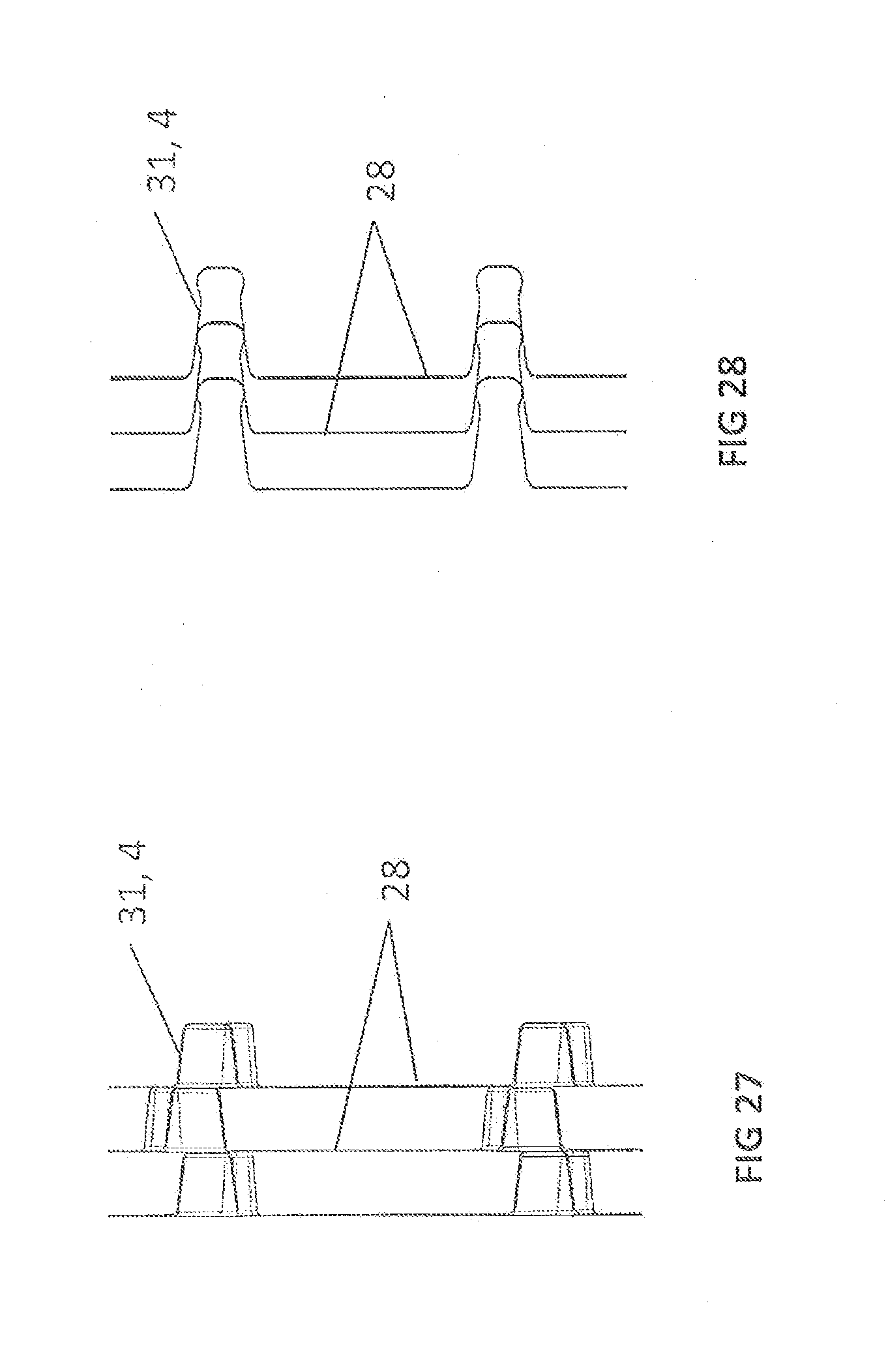
[0107] FIGS. 27 and 28 each show a side view of exemplary embodiments of a sheet strip stack 28 having a profiling 4 as spacer 31 and/or to guide the flow of a medium.
[0108] According to the exemplary embodiment of the invention illustrated in FIG. 27, the height of profiling 4 of sheet strips 28 matches the distance between sheet strips 28.
[0109] However, this height may exceed the distance if profilings 4 of sheet strips 28 are partially inserted into the negative structures of profilings 4 of adjacent sheet strips 28, as is apparent on the basis of the exemplary embodiment illustrated in FIG. 28. According to the invention, a height of profilings 4 of sheet strips 28 may thus match at least half the distance between two sheet strips 28.
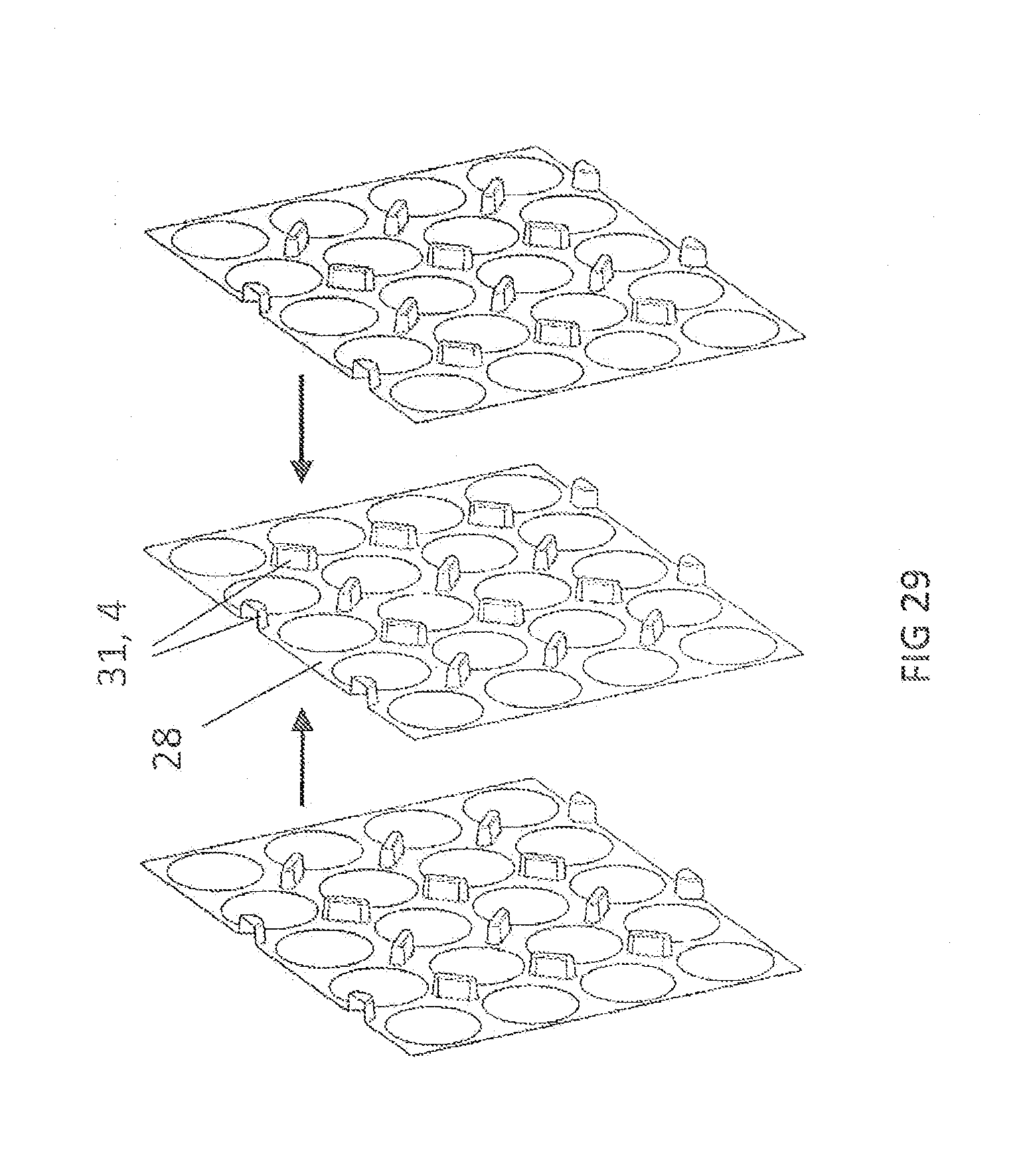
[0110] FIGS. 29 and 30 show possible configurations of guide sheets 28 in the TEG according to the invention, according to exemplary embodiments of the present invention.
[0111] Sheet strips 28 may be stacked in stacks of the same type and of the same orientation.
[0112] According to the schematic diagram illustrated in FIG. 29, adjacent sheet strips 28 may be alternatively and advantageously disposed such that they are alternatingly rotated 180 degrees in relation to each other for the purpose of joining a plurality of guide sheets 28, a center of sheet strip 28 representing the pivot point and the orthogonal to sheet strip 28 representing the rotation axis. This makes it possible to achieve a more uniform temperature distribution on the walls of the TEM tubes by compensating local heat transfer differences over the entire heat transfer surface. The orientation of profilings 4 in height remains the same. Profilings 4 and spacers 31 therefore face the same direction.
[0113] According to the invention, adjacent sheet strips 28 may likewise be situated such that they are alternately rotated 180 degrees in relation to each other or rotated tangentially, as shown on the basis of the exemplary embodiment of a guide sheet configuration 28 illustrated in FIG. 30. In this case, the center of sheet strip 28 represents the pivot point, and the tangent to sheet strip 28 in the width direction or depth direction represents the rotation axis. The orientation of profilings 4 of two adjacent sheet strips 28 does not remain the same, due to the fact that they are either oriented toward each other or facing away from each other.
[0114] FIG. 31 shows an isometric representation of one exemplary embodiment of an uneven sheet strip 28. Sheet strip 28 is corrugated in the area of recesses 29. According to this exemplary embodiment, sheet strips 28 may also be used for holding and positioning the TEM tubes within the TEG.
[0115] FIG. 32 shows a side view of a stack of a plurality of uneven sheet strips 28 according to the exemplary embodiment from FIG. 31.
[0116] The embodiments according to FIGS. 29, 30, 31 and 32 may be combined in another embodiment.
[0117] Alternatively, the heat exchanger described in connection with FIGS. 1 through 32 may be used not only to generate electricity but also for heating and/or cooling, so that the heat exchanger functions as a thermoelectric heater/cooler (TE-HC).
[0118] Accordingly, FIG. 33 shows an isometric representation of one embodiment of the heat exchanger as a thermoelectric heater or cooler 32. TE-HC 32 is designed without a housing, although it has two opposite axial diffusers 27, only one of axial diffusers 27 being provided with a reference numeral.
[0119] FIG. 34 shows a longitudinal sectional view of TE-HC 32 from FIG. 33. The figure shows a base 5, TEM tubes 14, diffusers 27 and guide sheets 28. In the interest of clarity, only one of TEM tubes 14, one of diffusers 27 and one of guide sheets 28 is provided with a reference numeral in each case.
[0120] According to the exemplary embodiment illustrated in FIG. 34, TE-HC 32 is a heat exchanger which is provided with thermoelectric modules (TEM) or TEM tubes 14, which, in turn, include thermoelectrically active materials. If the TEMs are operating using electricity, TE-HC 32 may be used as a heater or as a cooler, since the two opposite main surfaces of the TEMs are in contact with a heat source in the form of the first medium, e.g., coolant or air, on the one hand, and with a heat sink in the form of the second medium, e.g., air or coolant, on the other hand. The TEMs remove heat from the one medium and transport it to the other medium in the sense of a heat pump according to the Peltier effect. The media are conducted past each other accordingly within TE-HC 32.
[0121] If the air is guided on the outside of TEM tubes 14, TE-HC 32 may be designed without a housing and without radial diffusers. If the coolant or refrigerant is guided on the outside of TEM tubes 14, TE-HC 32 may be designed without axial diffusers 27.
[0122] FIG. 35 shows another exemplary embodiment of a thermoelectric heater or cooler 32, which does not have axial diffusers but does have radial diffusers 26.
[0123] The TEG described in connection with FIGS. 1 through 32, and the thermoelectric heater/cooler TE-HC described in connection with FIGS. 33 through 35, may also be designed as parallel heat exchangers, so that the first medium and the second medium are conducted past each other along the heat transfer route in either a cross flow or a unidirectional flow. The openings in the housing of the heat exchanger may be positioned at the axial ends of the housing. The apparatus may also be designed without radial diffusers.
[0124] In this connection, FIG. 36 shows an isometric representation of a sheet strip for an embodiment of the heat exchanger as a parallel heat exchanger according to one exemplary embodiment of the present invention. Sheet strip 28 may have a profiling 4 and be designed with further recesses 33 in addition to recesses 29, so that a flow on an outside of the TEM tubes may flow through a plurality of sheet strips 28 of the parallel heat exchanger.
[0125] The exemplary embodiments described have been selected only by way of example and may be combined with each other.
[0126] The invention being thus described, it will be obvious that the same may be varied in many ways. Such variations are not to be regarded as a departure from the spirit and scope of the invention, and all such modifications as would be obvious to one skilled in the art are to be included within the scope of the following claims.
* * * * *
D00000
D00001
D00002
D00003
D00004
D00005
D00006
D00007
D00008
D00009
D00010
D00011
D00012
D00013
D00014
D00015

D00016
D00017
D00018

D00019
D00020

D00021
D00022

D00023
D00024
D00025
D00026
D00027
D00028

D00029
D00030
XML
uspto.report is an independent third-party trademark research tool that is not affiliated, endorsed, or sponsored by the United States Patent and Trademark Office (USPTO) or any other governmental organization. The information provided by uspto.report is based on publicly available data at the time of writing and is intended for informational purposes only.
While we strive to provide accurate and up-to-date information, we do not guarantee the accuracy, completeness, reliability, or suitability of the information displayed on this site. The use of this site is at your own risk. Any reliance you place on such information is therefore strictly at your own risk.
All official trademark data, including owner information, should be verified by visiting the official USPTO website at www.uspto.gov. This site is not intended to replace professional legal advice and should not be used as a substitute for consulting with a legal professional who is knowledgeable about trademark law.