Compression Installation
Kolscheid; Hans-Gerd ; et al.
U.S. patent application number 12/310928 was filed with the patent office on 2012-12-27 for compression installation. Invention is credited to Hans-Gerd Kolscheid, Klaus Peters.
| Application Number | 20120324861 12/310928 |
| Document ID | / |
| Family ID | 38229928 |
| Filed Date | 2012-12-27 |
| United States Patent Application | 20120324861 |
| Kind Code | A1 |
| Kolscheid; Hans-Gerd ; et al. | December 27, 2012 |
Compression Installation
Abstract
A compressor plant with at least one gas turbine having a gas turbine compressor and with a steam turbine is disclosed, wherein a steam generation plant which is assigned to the gas turbine is operated with exhaust gases of the gas turbine, such that the steam generated in the steam generation plant drives the stream turbine. There is assigned at least one additional compressor for compressing a process medium. The compressor is connected directly to the gas turbine and/or the steam turbine such that the assigned compressor is driven in each case directly by the gas turbine and/or the steam turbine.
| Inventors: | Kolscheid; Hans-Gerd; (Duisburg, DE) ; Peters; Klaus; (Mulheim, DE) |
| Family ID: | 38229928 |
| Appl. No.: | 12/310928 |
| Filed: | September 11, 2007 |
| PCT Filed: | September 11, 2007 |
| PCT NO: | PCT/EP2007/059502 |
| 371 Date: | December 8, 2009 |
| Current U.S. Class: | 60/39.182 |
| Current CPC Class: | F25J 1/0283 20130101; F25J 1/0287 20130101; F25J 1/0022 20130101; F25J 1/0282 20130101; F25J 1/0289 20130101; F01K 23/064 20130101; F01K 23/10 20130101 |
| Class at Publication: | 60/39.182 |
| International Class: | F01K 23/10 20060101 F01K023/10 |
Foreign Application Data
| Date | Code | Application Number |
|---|---|---|
| Sep 15, 2006 | EP | 06019355.4 |
Claims
1.-8. (canceled)
9. A compression installation comprising: a gas turbine with a gas turbine compressor; a steam turbine with a steam generating installation being operated with exhaust gases of the gas turbine such that the steam generated in the steam generating installation drives the steam turbine, an additional compressor for compression of a process medium, the compressor being connected directly to the gas turbine such that the compressor is respectively driven directly by the gas turbine; and a starter-helper motor generator associated to the gas turbine, the starter-helper motor generator being used both as a helper motor (auxiliary motor) or as a generator.
10. A compression installation comprising: a gas turbine with a gas turbine compressor; a steam turbine with a steam generating installation being operated with exhaust gases of the gas turbine such that the steam generated in the steam generating installation drives the steam turbine, an additional compressor for compression of a process medium, the compressor being connected directly to the steam turbine such that the compressor is respectively driven directly by the steam turbine; and a starter-helper motor generator associated to the gas turbine, the starter-helper motor generator being used both as a helper motor (auxiliary motor) or as a generator.
11. A compression installation comprising: a gas turbine with a gas turbine compressor; a steam turbine with a steam generating installation being operated with exhaust gases of the gas turbine such that the steam generated in the steam generating installation drives the steam turbine, an additional compressor for compression of a process medium, the compressor being connected directly to the gas turbine and the steam turbine such that the compressor is respectively driven directly by the gas turbine and the steam turbine; and a starter-helper motor generator associated to the gas turbine, the starter-helper motor generator being used both as a helper motor (auxiliary motor) or as a generator.
12. The compression installation as claimed in claim 9, wherein the additional compressor is followed by an electrical process machine and/or a generator.
13. The compression installation as claimed in claim 10, wherein the additional compressor is followed by an electrical process machine and/or a generator.
14. The compression installation as claimed in claim 11, wherein the additional compressor is followed by an electrical process machine and/or a generator.
15. The compression installation as claimed in claim 9, wherein the additional compressor associated with the gas turbine and the gas turbine have a common shaft.
16. The compression installation as claimed in claim 10, wherein the additional compressor is associated with the steam turbine and the steam turbine have a common shaft.
17. The compression installation as claimed in claim 9, wherein both the gas turbine and the steam turbine each have an additional compressor respectively connected directly to the gas turbine and the steam turbine such that the respectively connected compressors are respectively driven directly by the gas turbine and the steam turbine.
18. The compression installation as claimed in claim 10, wherein both the gas turbine and the steam turbine each have an additional compressor respectively connected directly to the gas turbine and the steam turbine such that the respectively connected compressors are respectively driven directly by the gas turbine and the steam turbine.
19. The compression installation as claimed in claim 11, wherein both the gas turbine and the steam turbine each have an additional compressor respectively connected directly to the gas turbine and the steam turbine such that the respectively connected compressors are respectively driven directly by the gas turbine and the steam turbine.
20. The compression installation as claimed in claim 17, wherein the additional compressor which is respectively associated with the gas turbine and the steam turbine is used as a compressor in a gas liquefaction installation.
21. The compression installation as claimed in claim 18, wherein the additional compressor which is respectively associated with the gas turbine and the steam turbine is used as a compressor in a gas liquefaction installation.
22. The compression installation as claimed in claim 19, wherein the additional compressor which is respectively associated with the gas turbine and the steam turbine is used as a compressor in a gas liquefaction installation.
23. The compression installation as claimed in claim 9, wherein the gas turbine has a plurality of additional compressors which are driven directly by the gas turbine.
24. The compression installation as claimed in claim 10, wherein the steam turbine has a plurality of additional compressors driven directly by the steam turbine.
25. The compression installation as claimed in claim 11, wherein the gas turbine and the steam turbine each have a plurality of additional compressors driven directly by the gas turbine and the steam turbine.
26. The compression installation as claimed in claim 9, wherein the steam generating installation is in the form of a waste-heat boiler.
27. The compression installation as claimed in claim 10, wherein the steam generating installation is in the form of a waste-heat boiler.
28. The compression installation as claimed in claim 11, wherein the steam generating installation is in the form of a waste-heat boiler.
Description
CROSS REFERENCE TO RELATED APPLICATIONS
[0001] This application is the US National Stage of International Application No. PCT/EP2007/059502 filed Sep. 11, 2007 and claims the benefit thereof. The International Application claims the benefits of European Patent application No. 06019355.4 EP filed Sep. 15, 2006, both of the applications are incorporated by reference herein in their entirety.
FIELD OF INVENTION
[0002] The invention relates to a compression installation, in particular for gas liquefaction, having at least one gas turbine which comprises a gas turbine compressor, and having a steam turbine with a steam generating installation, which is associated with the gas turbine, being operated with exhaust gases from the gas turbine, such that the steam which is generated in the steam generating installation drives the steam turbine, with the combination of the gas turbine and the steam turbine having at least one additional associated compressor for compression of a process medium, which compressor is connected directly to the gas turbine and/or to the steam turbine such that the associated compressor can respectively be driven directly by the gas turbine and/or the steam turbine.
BACKGROUND OF INVENTION
[0003] It is known for either gas turbines or steam turbines to be used, for example, to generate electricity for electrical drive machines or electric motors for driving compressors. The known prior art has the disadvantage that the overall efficiency of the installations is restricted to the capabilities of the individual process. In this case, the efficiencies of gas turbines are about 40%, those of steam turbines are about 45%, and those of electrical process machines (for example electric motors) are about 98%. However, in the case of electrical process machines and electric motors, it must be remembered that the current which they require must be provided from a gas process (gas turbine), a steam process (steam turbine) or by a combination of the two processes. The efficiency for electricity generation is in this case at most 60%, with modern technology. Furthermore, complicated circuit technology is required in order to transmit the electrical power that is generated to the electrical process machine or to the electric motor. Furthermore, transmission losses in a system which has to convert the electrical energy in a frequency converter from one frequency range to another are likewise not negligible. The transmission losses may, for example, be up to about 5%.
[0004] The electrical process machines or the electric motors drive a compressor, for example, which can be used, for example, as a compressor for a gas liquefaction installation. A gas liquefaction installation such as this is known, for example, as an LNG (liquefied natural gas) installation. In this case, natural gas is cooled down to about -160.degree. C. In the process, the natural gas becomes liquid and is (with a smaller volume) then also easier to transport (normally in special transport apparatuses). In this case, the object of the compressors is to compress working media, normally working gases, which can absorb heat when subsequently expanded. This heat is taken from the natural gas in the so-called "cold box" of the LNG installation, and the natural gas is cooled down in this way. The working medium or working gas is in this case repeatedly compressed and expanded in a circuit.
[0005] The compressors are normally driven by the abovementioned electric motor, thus resulting in considerable (transmission) losses here since the power to be generated for the electric motor is generated either by the gas process or the steam process since the electric motor has to drive the compressor.
[0006] DE 21 02 770, U.S. Pat. No. 4,321,790 and WO 2005/024188 A2 each disclose combined gas and steam turbine installations which are also intended for driving a compressor. The described installations have significant efficiency losses, particularly during fluctuating operation.
SUMMARY OF INVENTION
[0007] An object of the invention is to improve a compression installation of the type mentioned initially, using simple means, such that the efficiency is improved and hazardous emissions are reduced at the same time.
[0008] According to the invention, the object is achieved by a compression installation as claimed in the claims.
[0009] Gas turbines and steam turbines are advantageously used separately to drive the at least one compressor directly, that is to say without the interposition of an electrical process machine or an electric motor. This leads to an efficiency improvement since the power is transmitted both from the gas turbine and from the steam turbine to the respectively associated at least one compressor by direct means, thus avoiding conversion losses such as those which occur in the generation of electrical power and the driving of compressors by means of electrical process machines or electric motors. However, at the same time, this also results in a reduction in hazardous emissions such as CO.sub.2 emissions, which is particularly advantageous with regard to commercial factors and the acquisition of emission rights. This is because, when fewer emissions are emitted, fewer emission rights must be acquired as well.
[0010] This becomes even more advantageous if the exhaust gas from the gas turbine can be used to fire a steam generating installation, preferably a waste-heat boiler, which in turn produces the steam required for the steam turbine. To this extent it is expedient for the gas turbine and the steam turbine to be combined with one another to form a gas and steam process. A plurality of gas turbines may, of course, be connected to one waste-heat boiler, in which case each gas turbine can also respectively drive at least one compressor in an expedient manner. The steam turbine may have a high-pressure part, a medium-pressure part and/or a low-pressure part, with a steam turbine preferably being provided that has all three pressure parts mentioned above. In this case, by way of example, the steam is first of all passed from the waste-heat boiler into the high-pressure part, from there into the medium-pressure part and finally into the low-pressure part, downstream from which the at least one compressor is arranged. The arrangement of the compressor downstream from the low-pressure part is, of course, not restricted to this arrangement. It is possible, for example, for the compressor to be arranged between the turbine elements or on the high-pressure side.
[0011] In order to further improve efficiency, it is advantageous if the at least one gas turbine and/or the steam turbine has or have a plurality of respectively associated compressors which are connected in series or in parallel with the at least one compressor.
[0012] It is feasible for the at least one compressor to be followed by a generator or an electrical process machine, or an electric motor, in order, for example, to drive other machines.
[0013] It is advantageous if the at least one compressor which is associated with the gas turbine, and the gas turbine, have a common shaft, as a result of which the efficiency is further improved. Two separate shaft parts of the respective component can, of course, also be provided, which are connected to one another by suitable means. Even when a plurality of compressors is connected in series, one common shaft may be provided. The at least one compressor which is associated with the steam turbine, and the steam turbine, may, of course, also have a common shaft, in which case, of course, separate shaft parts, as mentioned above, are also possible.
[0014] The respective compressor which is driven directly by the gas turbine or the steam turbine may, for example, be used as compressor in a gas liquefaction installation, for example an LNG installation.
BRIEF DESCRIPTION OF THE DRAWING
[0015] Further advantageous refinements of the invention are disclosed in the dependent claims and in the following FIGURE description. In the FIGURE, the single
[0016] FIG. 1 shows an outline illustration of a compression installation.
DETAILED DESCRIPTION OF INVENTION
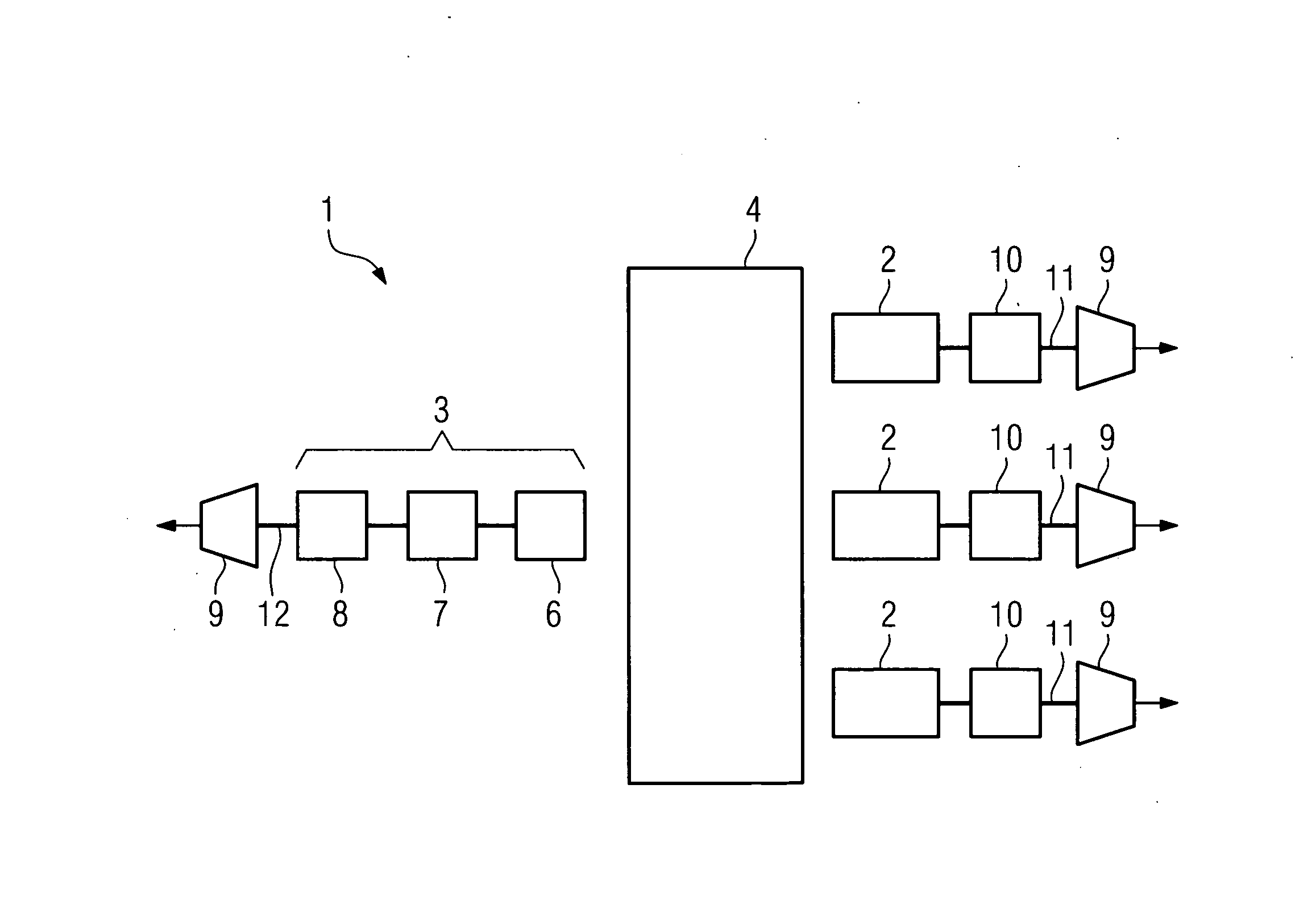
[0017] FIG. 1 shows a compression installation 1 which has at least one gas turbine 2 and one steam turbine 3. By way of example, three gas turbines 2 are provided in the illustrated exemplary embodiment.
[0018] The exhaust gases from the gas turbine 2 fire a steam generating installation 4, which is in the form of a waste-heat boiler. The steam which is generated in the steam generating installation 4 is supplied to the steam turbine 3, and drives it.
[0019] The illustrated gas turbines 2 have an associated starter-helper motor generator (SHMG) 10. This starter-helper motor generator (SHMG) 10 can be used both as helper motor (auxiliary motor) and as a generator. The starter should be understood as meaning that the motor--in a similar manner to that in the case of a car engine--represents the starter, and ensures that the gas turbine is brought to a rotation speed such that the gas turbine is able to drive the shaft train on its own.
[0020] In the compression installation 1 illustrated by way of example in FIG. 1, the gas process (gas turbine 2) and the steam process (steam turbine 3) are combined to form a gas and steam process.
[0021] According to the illustrated exemplary embodiment, the steam turbine 3 has a high-pressure part 6, a medium-pressure part 7 and a low-pressure part 8.
[0022] Both the at least one gas turbine 2 and the steam turbine 3 each have at least one associated compressor 9. The respective compressors 9 are respectively connected directly to the at least one gas turbine 2 and the steam turbine 3, with the at least one compressor 9 which is associated with the steam turbine 3 being arranged downstream from the low-pressure part 8 of the steam turbine 3. The compressors 9 which are respectively associated with the at least one gas turbine 2 and the steam turbine 3 are respectively driven directly by the gas turbine 2 and the steam turbine 3, without the interposition of an electrical process machine or an electric motor, in which case, in fact, the starter-helper motor generator (SHMG) 10 can be associated with the gas turbines.
[0023] The exemplary embodiment shown in FIG. 1 does not show that one or more compressors 9 may be followed by an electrical process machine or an electric motor, and/or a generator. The positioning of the compressor 9 in the shaft trains is, of course, not intended to be restricted to the disclosed position, but can be made variable.
[0024] It is possible for the at least one compressor 9 which is associated with the gas turbine 2, and the at least one gas turbine 2, to have a common shaft (line 11). Furthermore, the at least one compressor 9 which is associated with the steam turbine 3, or its low-pressure part 8, and the steam turbine 3, or the low-pressure part 8, may have a common shaft 12.
[0025] By way of example, the respective compressor 9 can compress a working medium or a working gas such that the working medium can absorb heat when it is subsequently expanded. For example, it is feasible for the working medium which is compressed in the respective compressor 9 to be supplied to a gas liquefaction installation, for example, an LNG installation (liquefied natural gas), in order to cool down natural gas.
* * * * *
D00001
XML
uspto.report is an independent third-party trademark research tool that is not affiliated, endorsed, or sponsored by the United States Patent and Trademark Office (USPTO) or any other governmental organization. The information provided by uspto.report is based on publicly available data at the time of writing and is intended for informational purposes only.
While we strive to provide accurate and up-to-date information, we do not guarantee the accuracy, completeness, reliability, or suitability of the information displayed on this site. The use of this site is at your own risk. Any reliance you place on such information is therefore strictly at your own risk.
All official trademark data, including owner information, should be verified by visiting the official USPTO website at www.uspto.gov. This site is not intended to replace professional legal advice and should not be used as a substitute for consulting with a legal professional who is knowledgeable about trademark law.