Method Of Application Of Closure Liner In Hot Fill Packages
MILLER; Albert R. ; et al.
U.S. patent application number 13/168209 was filed with the patent office on 2012-12-27 for method of application of closure liner in hot fill packages. This patent application is currently assigned to Phoenix Closures, Inc.. Invention is credited to Len Ekkert, Albert R. MILLER.
| Application Number | 20120324836 13/168209 |
| Document ID | / |
| Family ID | 47360494 |
| Filed Date | 2012-12-27 |


| United States Patent Application | 20120324836 |
| Kind Code | A1 |
| MILLER; Albert R. ; et al. | December 27, 2012 |
METHOD OF APPLICATION OF CLOSURE LINER IN HOT FILL PACKAGES
Abstract
A method of applying a liner to a container mouth in a hot-fill operation, said method comprising the steps of: placing the liner over a mouth sealing surface of the container; heating the liner by induction or conduction; and cooling the liner immediately thereafter while biasing the liner against the mouth sealing surface for a sufficient length of time to permit curing and sealing of the liner to the mouth sealing surface.
| Inventors: | MILLER; Albert R.; (Naperville, IL) ; Ekkert; Len; (Naperville, IL) |
| Assignee: | Phoenix Closures, Inc. Naperville IL |
| Family ID: | 47360494 |
| Appl. No.: | 13/168209 |
| Filed: | June 24, 2011 |
| Current U.S. Class: | 53/478 |
| Current CPC Class: | B65B 7/2878 20130101; B65B 51/32 20130101; B65B 51/18 20130101 |
| Class at Publication: | 53/478 |
| International Class: | B65B 51/10 20060101 B65B051/10; B65B 51/32 20060101 B65B051/32 |
Claims
1. A method of applying a liner to a container mouth in a hot-fill operation, said method comprising the steps of: a) placing the liner over a mouth sealing surface of the container; b) heating the liner by induction or conduction; and c) cooling the liner immediately thereafter while biasing the liner against the mouth sealing surface for a sufficient length of time to permit curing and sealing of the liner to the mouth sealing surface.
2. The method of claim 1 wherein the cooling of the liner is accomplished by directing a refrigerated media against the liner.
3. The method of claim 1 wherein the cooling of the liner is accomplished by the application of a refrigerated surface to the liner.
4. The method of claim 1 wherein the step of biasing the liner against the mouth sealing surface is accomplished by biasing a first conveyor belt against the liner while supporting the container with a second conveyor belt.
5. The method of claim 1 wherein the refrigerated media is water.
6. The method of claim 2 wherein the refrigerated media is air.
7. A method of applying a liner to a container mouth in a hot-fill operation, said method comprising the steps of: a) placing the liner over a mouth sealing surface of the hot-filled container; b) heating the liner by induction or conduction; and cooling the liner immediately thereafter while biasing the liner against the mouth sealing surface for a sufficient length of time to permit curing and sealing of the liner to the mouth sealing surface. c) cooling the liner and the container immediately by applying a refrigerated surface against the liner and directing a refrigerated media against the container thereafter while biasing the liner against the mouth sealing surface for a sufficient length of time to permit curing and sealing of the liner to the mouth sealing surface.
8. The method of claim 1 wherein the step of biasing the liner against the mouth sealing surface is accomplished by biasing a first conveyor belt against the liner on the mouth sealing surface while supporting the container with a second conveyor belt.
Description
FIELD OF THE INVENTION
[0001] The invention relates to an inner seal for a container and more particularly to a pull-tab for the inner seal to permit a proper seal while allowing for easy removal of the inner seal to the container.
BACKGROUND OF THE INVENTION
[0002] A heat sealable inner seal is often used in sealing a container for products such as anti-freeze, peanut butter, mayonnaise, liquid detergent, etc. Such an inner seal prevents leakage and is also popular for providing an indication of whether there has been tampering with the contents of a container.
[0003] Presently, a heat sealable inner seal generally includes a multi layer composite structure with an upper layer of metallic foil which is attached to a lower layer of adhesive material which bonds the heat seal material. The inner seal also can include an upper backing layer. Generally, the inner seals are inserted into caps and shipped to a packager of containers. The packager places the caps onto filled containers, with the coating of heat sealable material being in contact with the land area of the neck of the containers. The containers then pass through a conduction heating system which conducts heat into the foil, under an induction heater which generates heat within the metallic foil causing the temperature of the foil to increase. The high temperature of the foil melts the attached heat sealable adhesive layer, causing the inner seal to bond to the container.
[0004] In a hot fill process and after the product is filled in the container, the liner, when placed on the container, may have an edge curl up, thus will not seal properly. The bonding between the heat sealable layer and container may be weak or may not occur and prevent the inner seal from performing its sealing function. As a result, the predominant closures for hot-fill have been metal or closures with imbedded liners. Therefore, it is desirable to maintain the liner in contact with the mouth of the container and to heat the foil to a temperature within a desired temperature range to ensure proper bonding of the inner seal to the container.
SUMMARY OF THE INVENTION
[0005] In hot-fill food packaging, with bottles, the use of liners is increasing. The process generally involves filling product into the bottle or other container, placing the liner on the mouth of the bottle or other containers, and heat sealing through induction or conduction. The subject invention involves immediately cooling the liner while holding it against the bottle mouth sealing the surface. The cooling may be accomplished by sprayed water or other application of water, a refrigerated plate or simply blowing refrigerated air at the liner. The liner may be secured against the mouth of the bottle by the refrigerated plate. A conveyor may also be used to apply pressure to the liner while it is on the mouth of the bottle.
BRIEF DESCRIPTION OF THE FIGURES
[0006] The present invention will be more readily apparent from the following detailed description of the invention and the appended claims, when taken in conjunction with the accompanying drawings in which:
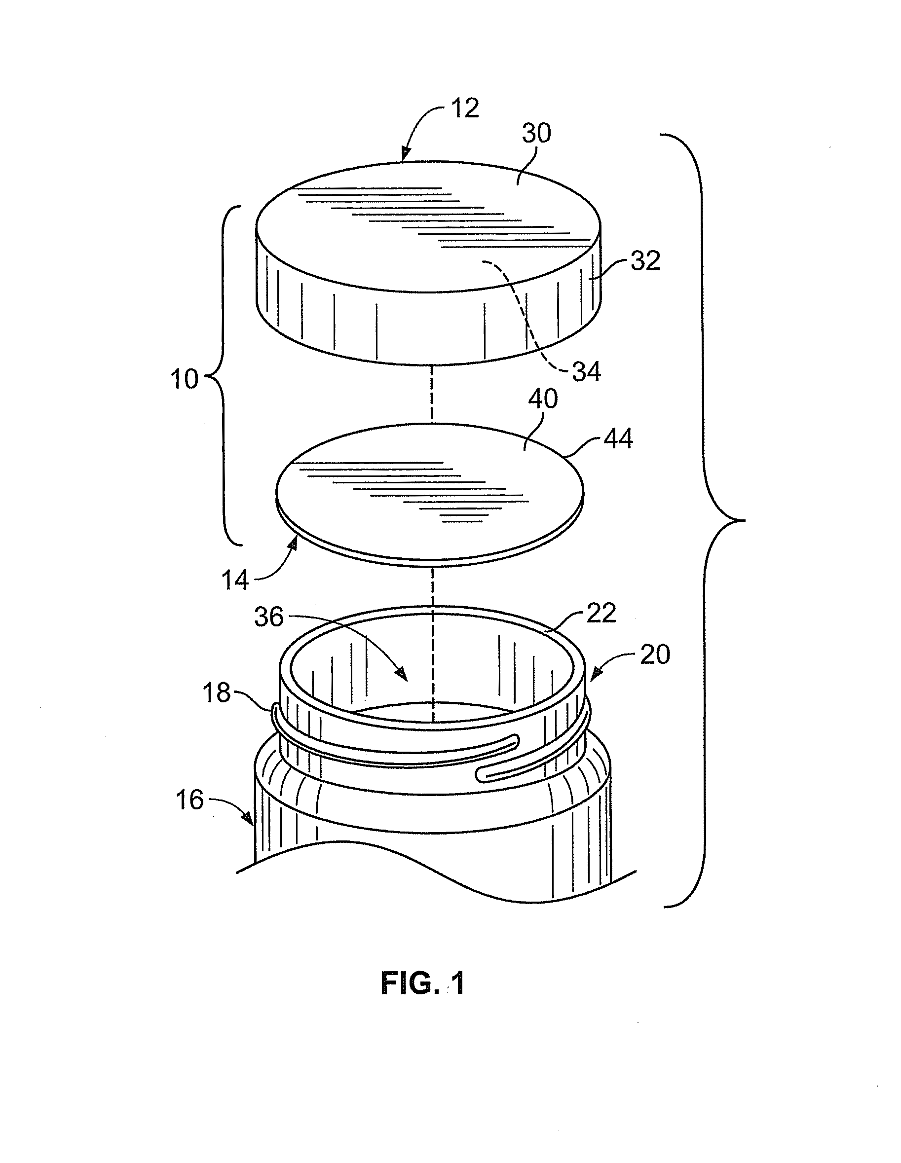
[0007] FIG. 1 is an exploded perspective view of a closure package and an associated container, the closure package including a liner having a pull-tab embodying the principles of the present invention;
[0008] FIG. 2 is a partial cross-sectional view of an exemplary laminate structure of the liner material;
[0009] FIG. 3 is a top plan view of a liner with pull-tab;
[0010] FIG. 4 is a side view of an apparatus for utilizing the subject inventive method; and
[0011] FIG. 5 is a side view of an alternate apparatus for utilizing the subject inventive method.
DETAILED DESCRIPTION OF THE PREFERRED EMBODIMENTS
[0012] While the present invention is susceptible of embodiment in various forms, there is shown in the drawings and will hereinafter be described a presently preferred embodiment with the understanding that the present disclosure is to be considered an exemplification of the invention and is not intended to limit the invention to the specific embodiment illustrated.
[0013] Referring now to the figures and particularly to FIG. 1, there is shown a closure package 10 including a closure cap 12 and a liner 14 showing a typical container cap and liner. The package 10 is for use with an associated container 16. The exemplary container 16 has a threaded neck portion 18 having a finish 20. The finish 20 is that portion of the container 16 including the upper region which engages the cap 12, e.g., the threaded area 18 and an uppermost sealing surface 22 of the container 16. The container threads 18 engage complementary threads (not shown) formed on an inner surface of the cap 12. It will be recognized by those skilled in the art that the closure package 10 described herein can be used with containers having a snap-like or beaded engagement configuration.
[0014] The cap 12 has a top wall portion 30 and a depending skirt portion 32 depending from the top wall portion 30. The inner surface 34 of the top wall portion 30 is adapted to coact with the sealing surface 22 of the container 16 to form a seal therebetween. When the package 10 is assembled, the liner 14 comprises a circular disc and resides between the top wall portion 30 of the cap 12 and the sealing surface 22 of the container 16, spanning the opening or mouth 36 of the container 16.
[0015] The liner 14 has a central portion 40 that is positioned over and in use, sealed to the sealing surface 22 of the container 16. As shown in FIG. 3, a tab 42 may be integral with the central portion 40, and extends from a periphery 44 thereof. The tab 42 defines a grasping portion 46, that, when folded, is adapted to facilitate removing the liner 14 from the container 16.
[0016] In one embodiment, as illustrated in FIG. 2, the liner 14 is formed from a laminate material M having a resilient substrate layer 50, a foil or like gas-impermeable layer 52, and a heat activated bonding layer 54, such as a heat activated adhesive. In a current embodiment, the resilient substrate layer 50 is a closed cell foam material, but can be chip board or paper backed and/or coated and is relatively impervious to the environs and establishes an air-tight seal between the container 16 contents and the environs. The resilient material layer 50 permits the cap 12 to be closely fitted to, and tightened onto, the container 16.
[0017] Attention is now directed to FIG. 4. where a linear-conveyor embodiment of a sealing apparatus, generally designated 70, is illustrated for sealing a heat-sealable liner 14 to a container 20 having an open end 36 (FIG. 1) upon which liner 40 is to be fused. Sealing apparatus 70 includes an elongated frame 73, and a first surface 76 for support and moving the container/liner combination along a pathway. A second conveyor assembly, generally designated 77, is coupled to frame 73 and extends along and is adjacent and directly above first surface 76. Second conveyor assembly 77 includes a relatively rigid second surface 90 in opposed moving relation to the first surface 76 for further transport of the container/liner combination between the first and second conveyor assemblies along the pathway. A cooling element 92 may be positioned longitudinally and parallel to a portion of one of first surface 76 and second surface 90. The cooler directs refrigerated air against conductive plates 94 on second conveyor assembly 77. The conductive plates 94 are cooled by the cooling element 92 and travel along the conveyor belt path for contact with the container closure so that the heat of the hot-fill process is absorbed by refrigerated surfaces of the conductive plates 94. The conductive plates 94 then travel further along the pathway to be cooled by the cooler 92 again.
[0018] The containers may be cooled by spraying the bottles with a refrigerant or other fluid, such as water, to cool the containers while pressure is being applied to the liner. This is shown in FIG. 5 with water spray line 95. If desired, the liner may be cooled by the sprayed media also. Further, a blower 93, as shown in FIG. 5, may be used to blow refrigerated air against the containers to cool down the containers and their contents after a hot fill. The cooling media may also be directed against the liner.
[0019] Thus, the liner is cooled after the hot-fill process. Further, the second conveyor assembly 77 biases the second surface 90 thereof toward the first surface 76 against the containers 15 on the first conveyor to provide a substantially constant pressure between sealing surface 22 and liner 40 as the two travel on the conveyor as a unit.
[0020] As each container/liner combination 15 passes between the opposing first and second conveyor assemblies 76 and 77, respectively, they cooperate to squeeze liner 40 against container mouth or sealing surface 22 at a constant pressure during passage through the pathway. A constant pressure is thus applied between the container mouth sealing surface 22 and the liner 40 which squeezes and maintains pressure during the cooling process of the liner 40, to thereby keep the liner in a sealed condition after the fusing of the liner in the induction process.
[0021] While the container/liner assembly travels along first conveyor assembly, a blast of refrigerated media such as air or liquid from refrigeration blower 93 may be directed to the liner surface as graphically depicted in FIG. 5 for a duration and at a temperature sufficient to cool the liner immediately after the induction or conduction heating and ensure curing and sealing of the liner upon the container mouth.
[0022] It will be understood that the foregoing description is of preferred exemplary embodiments of the invention and that the invention is not limited to the specific forms shown or described herein. Various modifications may be made in the design, arrangement, and type of elements disclosed herein, as well as the steps of making and using the invention without departing from the scope of the invention as expressed in the appended claims.
* * * * *
D00000
D00001
D00002
D00003
D00004
XML
uspto.report is an independent third-party trademark research tool that is not affiliated, endorsed, or sponsored by the United States Patent and Trademark Office (USPTO) or any other governmental organization. The information provided by uspto.report is based on publicly available data at the time of writing and is intended for informational purposes only.
While we strive to provide accurate and up-to-date information, we do not guarantee the accuracy, completeness, reliability, or suitability of the information displayed on this site. The use of this site is at your own risk. Any reliance you place on such information is therefore strictly at your own risk.
All official trademark data, including owner information, should be verified by visiting the official USPTO website at www.uspto.gov. This site is not intended to replace professional legal advice and should not be used as a substitute for consulting with a legal professional who is knowledgeable about trademark law.