Athletic Shoe
Soumokil; Jeff ; et al.
U.S. patent application number 13/309446 was filed with the patent office on 2012-12-27 for athletic shoe. This patent application is currently assigned to Oakley, Inc.. Invention is credited to Peter Backus, Troy McMullen, Jeff Soumokil.
| Application Number | 20120324762 13/309446 |
| Document ID | / |
| Family ID | 47360462 |
| Filed Date | 2012-12-27 |


| United States Patent Application | 20120324762 |
| Kind Code | A1 |
| Soumokil; Jeff ; et al. | December 27, 2012 |
ATHLETIC SHOE
Abstract
An athletic shoe is disclosed having a two component traction system. The traction system includes an upper and an outsole. The outsole is coupled to the upper. The outsole includes at least a first traction portion and a second traction portion. Each of the first traction portion and the second traction portion define a portion of a bottom surface of the shoe. The first traction portion includes a plurality of first traction elements that provide the shoe with first traction characteristics. The second traction portion comprises a plurality of second traction elements that differ from the first traction elements in size, shape or density and provide the shoe with second traction characteristics different from the first traction characteristics. At least one of the first traction portion and the second traction portion is replaceable.
| Inventors: | Soumokil; Jeff; (Yorba Linda, CA) ; Backus; Peter; (Newberg, OR) ; McMullen; Troy; (Corona, CA) |
| Assignee: | Oakley, Inc. Foothill Ranch CA |
| Family ID: | 47360462 |
| Appl. No.: | 13/309446 |
| Filed: | December 1, 2011 |
Related U.S. Patent Documents
| Application Number | Filing Date | Patent Number | ||
|---|---|---|---|---|
| 61499640 | Jun 21, 2011 | |||
| Current U.S. Class: | 36/103 |
| Current CPC Class: | A43B 1/0027 20130101; A43B 1/0081 20130101; A43B 3/26 20130101; A43B 13/141 20130101; A43B 7/12 20130101; A43B 13/122 20130101 |
| Class at Publication: | 36/103 |
| International Class: | A43B 5/00 20060101 A43B005/00; A43B 13/22 20060101 A43B013/22 |
Claims
1. An athletic shoe having a two component traction system, comprising: an upper; an outsole coupled to the upper, the outsole comprising at least a first traction portion and a second traction portion, wherein each of the first traction portion and the second traction portion define a portion of a bottom surface of the shoe, wherein the first traction portion comprises a plurality of first traction elements that provide the shoe with first traction characteristics and the second traction portion comprises a plurality of second traction elements that differ from the first traction elements in size, shape, hardness, pattern or density and provide the shoe with second traction characteristics different from the first traction characteristics; wherein at least one of the first traction portion and the second traction portion is replaceable.
2. The athletic shoe of claim 1, wherein only the second traction portion is replaceable.
3. The athletic shoe of claim 1, wherein the first traction elements are lugs unitarily formed with a molded portion of the outsole that forms the first traction portion.
4. The athletic shoe of claim 3, wherein each of the lugs comprises an elliptical portion and a pair of fins that extend from the elliptical portion.
5. The athletic shoe of claim 4, wherein the pair of fins extend from opposing ends of the elliptical portion at an angle with respect to a major axis of the opposing ends and to the same side of the major axis.
6. The athletic shoe of claim 3, wherein the plurality of lugs comprises a first lug adjacent to a second lug, wherein each of the lugs comprises an elliptical portion, and wherein a fin extends between the elliptical portion of the first and second lug.
7. The athletic shoe of claim 5, wherein the plurality of lugs comprises a first lug adjacent to a second lug, a first pair of fins of the first lug extending from a first elliptical portion of the first lug towards the adjacent second lug, a second pair of fins of the second lug extending from a second elliptical portion of the second lug towards the adjacent first lug.
8. The athletic shoe of claim 3, wherein the second traction elements are abrasive grains.
9. The athletic shoe of claim 3, wherein the first traction portion comprises at least 30 lugs.
10. The athletic shoe of claim 3, wherein the lugs have a height of less than or equal to about 6 millimeters.
11. The athletic shoe of claim 3, wherein the second traction elements are recessed above the bottommost surface of the lugs.
12. The athletic shoe of claim 11, wherein the outsole comprises at least one wear bar extending generally along an approximately longitudinal, superior/inferior extending central plane of the shoe, wherein a bottommost surface of the at least one wear bar is positioned below the second traction elements.
13. The athletic shoe of claim 1, wherein the first traction portion comprises a forefoot section and a heel section, each of which define a perimeter, wherein the second traction portion comprises at least one forefoot insert and at least one heel insert, wherein the at least one forefoot insert is positioned within the perimeter of the forefoot section and the at least one heel insert is positioned within the perimeter of the heel section.
14. The athletic shoe of claim 13, wherein the at least one forefoot insert comprises a first forefoot insert and a second forefoot insert spaced from one another on opposite sides of a phalangeal medial-lateral plane of the athletic shoe.
15. A golf shoe having a two component traction system, comprising: an upper; a permanent outsole portion permanently coupled to the upper, the permanent outsole portion comprising a base and a plurality of lugs unitarily formed with the base and extending downwardly from the base; a replaceable outsole portion replaceably coupled to the upper, the replaceable outsole portion comprising a base and a plurality of traction elements unitarily formed with the base and extending downwardly from the base.
16. The golf shoe of claim 15, wherein the plurality of traction elements are abrasive grains.
17. The golf shoe of claim 15, wherein the plurality of traction elements are generally pyramid-shaped spikes.
18. The golf shoe of claim 15, wherein the plurality of traction elements are microfibers.
19. The golf shoe of claim 15, wherein the replaceable outsole portion is coupled to the upper by a hook and loop fastener.
20. The golf shoe of claim 19, further comprising an insole board, wherein the upper is coupled to the insole board and the replaceable outsole portion is coupled directly to the insole board.
21. The golf shoe of claim 15, wherein the permanent outsole portion comprises a forefoot section and a heel section, each of which define a perimeter, wherein the replaceable outsole portion comprises at least one forefoot insert and at least one heel insert, wherein the at least one forefoot insert is positioned within the perimeter of the forefoot section and the at least one heel insert is positioned within the perimeter of the heel section.
22. The golf shoe of claim 21, wherein the at least one forefoot insert comprises a first forefoot insert and a second forefoot insert spaced from one another on opposite sides of a phalangeal medial-lateral plane of the golf shoe.
Description
RELATED APPLICATIONS
[0001] Related applications are listed in an Application Data Sheet (ADS) filed with this application. The entirety of each related application listed in the ADS is incorporated by reference herein.
BACKGROUND OF THE INVENTION
[0002] 1. Field of the Invention
[0003] The present disclosure relates generally to shoes, and more particularly to a traction system for an athletic shoe.
[0004] 2. Description of the Related Art
[0005] Historically, traction for shoes (e.g., athletic shoes, such as golf shoes) intended to be worn on turf (e.g., natural or artificial turf) was provided by pointed or downwardly conically converging metal spikes that penetrate the turf. The metal spikes were initially permanently attached to the golf shoe outsole, experienced limited wear and lasted for many years. Ultimately, metal spikes became replaceable components and were provided with threaded stems that could engage and be disengaged from a correspondingly threaded receptacle mounted in a shoe outsole.
[0006] Replaceable plastic cleats with a variety of traction elements (e.g., in the form of generally downwardly projecting teeth, legs, ribs, etc.) have also been developed and marketed. There are currently two primary types of plastic cleats being commercially utilized. One type has relatively long flexible legs (i.e., dynamic traction elements) that extend from a cleat hub and flex under the weight of the wearer of a golf shoe so as to tangle with turf and provide traction. Examples of cleats with dynamic traction elements are described and disclosed in U.S. Pat. No. 6,305,104 (McMullin '104), U.S. Pat. No. 6,834,445 (McMullin '445) and U.S. Pat. No. 7,040,043 (McMullin '043). These cleats are typically over 7.5 mm in overall cleat height, and this extra height provides traction as the legs, when fully flexed and during flexure, tangle with grass on fairways and in rough. The dynamic traction elements are said to flex under the weight of the golfer, thereby spreading outwardly along the surface of the green without puncturing the turf.
[0007] The second type of modern plastic cleat is one with static traction elements (i.e., elements that are substantially rigid and do not flex) that extend from the cleat hub. In order to protect greens, these cleats are shorter, typically a maximum of 6-6.25 mm in overall cleat height so as to limit any turf penetration that might occur. These cleats, although made of plastic material, are rigid and, because of their reduced height, are somewhat less effective in tangling or even biting into grass or thatch as the golfer walks on fairways and in rough.
[0008] For almost as long as they have been in use, golf spikes (and similar structures provided on athletic shoes for other turf sports) have also been known to adversely affect the turf of golf courses (or other playing surfaces), and particularly putting greens. The large spikes tear into the putting green surface, particularly when a golfer drags his or her feet as many do, leaving "spike marks" that disrupt the carefully manicured surface and adversely affect the trajectories of putted golf balls. So well known are spike marks in golf that the rules of the game have been adapted to account for their presence (the rules prohibit repairing spike marks before putting). In addition to affecting players` putting, spike marks also affect groundskeepers, who after a day of play by numerous spike-wearing golfers have to spend hours repairing the various putting greens on their golf courses.
[0009] In addition to the annoyance to players and groundskeepers caused by the marks that they leave, traditional golf shoe spikes also affect the health of grass all over the golf course, not only on greens. First, the spikes penetrate a significant distance into the ground, frequently damaging a portion of the grass plant above the roots, known as the "crown." Damage to the crown often kills the plant. Second, the spikes pick up seeds of undesirable weeds and grasses and inoculate those seeds into the greens, causing growth of undesirable plants.
[0010] Traditional metal or other rigid golf spikes are also damaging to the floor surfaces of golf clubhouses, and may actually exacerbate slipping on certain clubhouse floor surfaces such as marble. Traditional metal golf spikes even cause damage to paved outdoor walkways. Replacing worn traction elements on any of the foregoing designs can be tedious, and changing the traction elements such as to accommodate use on different surfaces is difficult or impossible.
[0011] Thus, notwithstanding the various efforts in the prior art, there remains a need for improved traction systems for shoes, particularly for those intended for use on surfaces such as turf.
SUMMARY OF THE INVENTION
[0012] There is provided in accordance with one aspect of the present inventions, an athletic shoe having a two component traction system. The shoe comprises an upper and an outsole. The outsole is coupled to the upper and comprises at least a first traction portion and a second traction portion. Each of the first traction portion and the second traction portion define a portion of a bottom surface of the shoe. The first traction portion comprises a plurality of first traction elements that provide the shoe with first traction characteristics. The second traction portion comprises a plurality of second traction elements that differ from the first traction elements in size, shape, hardness, pattern or density and provide the shoe with second traction characteristics different from the first traction characteristics. At least one of the first traction portion and the second traction portion is replaceable.
[0013] There is provided in accordance with another aspect of the present inventions, a golf shoe having a two component traction system. The shoe comprises an upper, a permanent outsole portion, and a replaceable outsole portion. The permanent outsole portion is permanently coupled to the upper. The permanent outsole portion comprises a base and a plurality of lugs unitarily formed with the base and extending downwardly from the base. The replaceable outsole portion is replaceably coupled to the upper. The replaceable outsole portion comprises a base and a plurality of traction elements unitarily formed with the base and extending downwardly from the base.
[0014] There is provided in accordance with another aspect of the present inventions an athletic shoe having a two component traction system. The shoe comprises an upper and an outsole. The outsole is coupled to the upper and comprises at least a first traction portion and a second traction portion. Each of the first traction portion and the second traction portion define a portion of a bottom surface of the shoe. The first traction portion comprises a plurality of first traction elements that provide the shoe with first traction characteristics. The second traction portion comprises a plurality of second traction elements that differ from the first traction elements in size, shape, hardness, pattern or density and provide the shoe with second traction characteristics different from the first traction characteristics. The first traction elements define a perimeter around a central region on the bottom surface of the shoe. The central region is free of first traction elements and is at least partially covered by the second traction elements.
[0015] There is provided in accordance with another aspect of the present inventions an athletic shoe having a two component traction system. The shoe comprises an upper and an outsole. The outsole is coupled to the upper and comprises at least a first traction portion and a second traction portion. Each of the first traction portion and the second traction portion define a portion of a bottom surface of the shoe. The first traction portion comprises a plurality of first traction elements that provide the shoe with first traction characteristics. The second traction portion comprises a plurality of second traction elements that differ from the first traction elements in size, shape, hardness, pattern or density and provide the shoe with second traction characteristics different from the first traction characteristics. The second traction elements are recessed above the first traction elements.
[0016] There is provided in accordance with another aspect of the present inventions an athletic shoe having a two component traction system. The shoe comprises an upper and an outsole. The outsole is coupled to the upper and comprises at least a first traction portion and a second traction portion. Each of the first traction portion and the second traction portion define a portion of a bottom surface of the shoe. The first traction portion comprises a plurality of first traction elements that provide the shoe with first traction characteristics. The second traction portion comprises a plurality of second traction elements that differ from the first traction elements in size, shape, hardness, pattern or density and provide the shoe with second traction characteristics different from the first traction characteristics. The second traction elements form a central region at least partially covering the bottom surface of the shoe. The central region is surrounded by a perimeter defined by the first traction elements and is free of the first traction elements.
[0017] In some embodiments, the central region covers between approximately 20% and 80% of the bottom surface of the shoe.
[0018] In some embodiments, the central region covers at least 25% of the bottom surface of the shoe.
[0019] In some embodiments, the central region comprises a central forefoot region and a central heel region, and the perimeter comprises a first sub-perimeter around the forefoot region and a second sub-perimeter around the heel region.
[0020] In some embodiments, the central forefoot region comprises a first forefoot region and a second forefoot region spaced from one another on opposite sides of a phalangeal medial-lateral plane of the athletic shoe.
[0021] In some embodiments, approximately the entirety of the central region is covered by the second traction elements.
[0022] There is provided in accordance with another aspect of the present inventions an athletic shoe having a two component traction system. The shoe comprises an upper and an outsole. The outsole is coupled to the upper and comprises at least a first traction portion and a second traction portion. Each of the first traction portion and the second traction portion define a portion of a bottom surface of the shoe. The first traction portion comprises a plurality of first traction elements that provide the shoe with first traction characteristics. The second traction portion comprises a plurality of second traction elements that differ from the first traction elements in size, shape, hardness, pattern or density and provide the shoe with second traction characteristics different from the first traction characteristics. The second traction elements are recessed above the first traction elements.
[0023] In some embodiments, the first traction elements comprise at least one of a width and length that is greater than a width of the second traction elements.
[0024] There is provided in accordance with another aspect of the present inventions a method for replacing a first traction portion of an athletic shoe having a two portion traction system, wherein each traction portion defines a portion of the bottom surface of the shoe and a second traction portion is permanently coupled to the shoe. The method comprises removing the first traction portion from the remainder of the shoe and replacing the first traction portion with a replacement traction portion sized and shaped to replace the first traction portion. In some arrangements, the removal of the first traction portion comprises peeling the first traction portion from the remainder of the shoe. In some arrangements, the first traction portion can include several individual sections and the method comprises replacing one or more of the several sections.
[0025] There is provided in accordance with another aspect of the present inventions a replacement traction portion for an athletic shoe having a two component traction system. The replacement traction portion is configured to be releasably secured to the shoe such that the replacement traction portion defines a portion of the bottom surface of the shoe. The replacement traction portion includes traction elements that provide the shoe with traction characteristics when the replacement traction portion is coupled to the shoe. In one arrangement, the traction elements comprise grains having an average particle diameter of between about 8.4 and 1815 micrometer (.mu.m) and the opposite side of the replacement traction portion comprises one of a hook portion and a loop portion of a hook-and-loop fastener to complement the other of the hook portion and the loop portion provided on the shoe. In one arrangement, the replacement traction portion is substantially U-shaped. The replacement traction portion may be provided in a kit containing a set of replacement traction portions configured to replace some or all of the original traction portions of a pair of shoes. The kit may contain three replacement traction portions for each one of the pair of shoes. Each of the three replacement portions may be substantially U-shaped.
BRIEF DESCRIPTION OF THE DRAWINGS
[0026] These and other features, aspects and advantages are described herein with reference to drawings of preferred embodiments, which are intended to illustrate and not to limit the inventions. The drawings contain thirteen (13) figures.
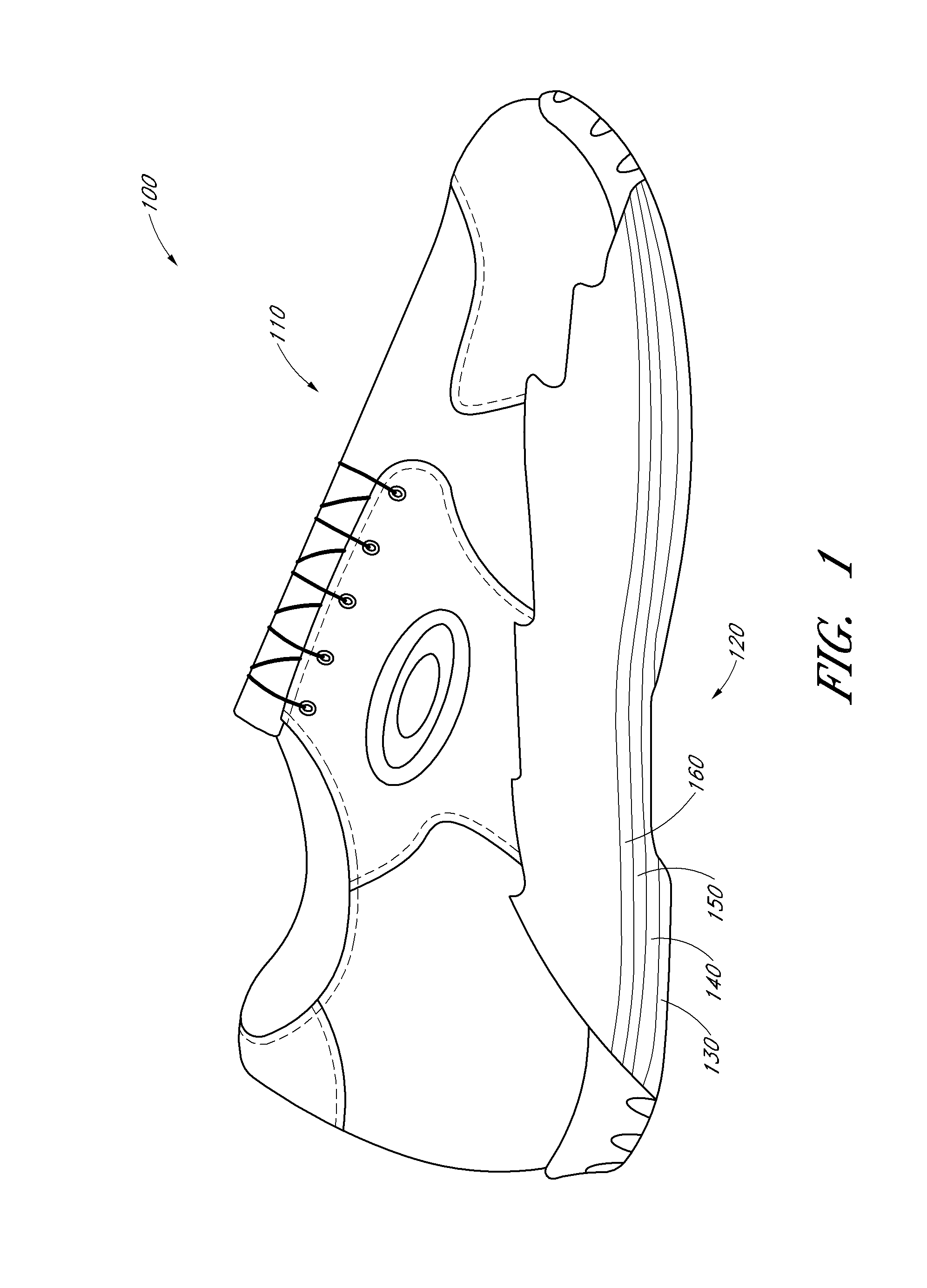
[0027] FIG. 1 is a side partial cross-sectional view of an embodiment of a shoe.
[0028] FIGS. 2 and 3 are side and bottom views, respectively, of an embodiment of a traction system for a shoe.
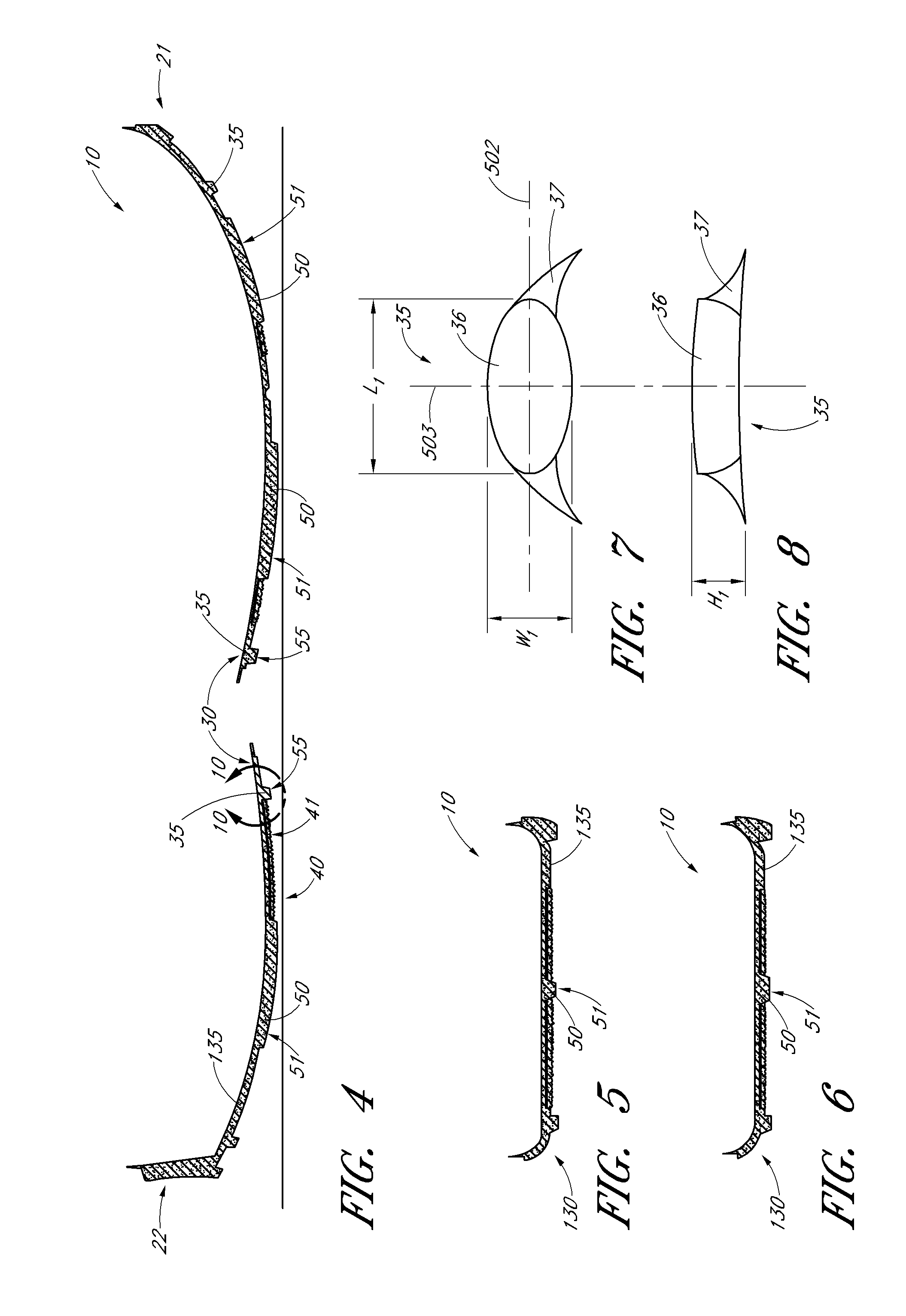
[0029] FIG. 4 is a side cross-sectional view of an embodiment of a traction system for a shoe taken along line 4-4 of FIG. 3.
[0030] FIG. 5 is a front cross-sectional view of an embodiment of a traction system for a shoe taken along line 5-5 of FIG. 3.
[0031] FIG. 6 is a front cross-sectional view of an embodiment of a traction system for a shoe taken along line 6-6 of FIG. 3.
[0032] FIGS. 7 and 8 are bottom and side views, respectively, of a traction element for a shoe.
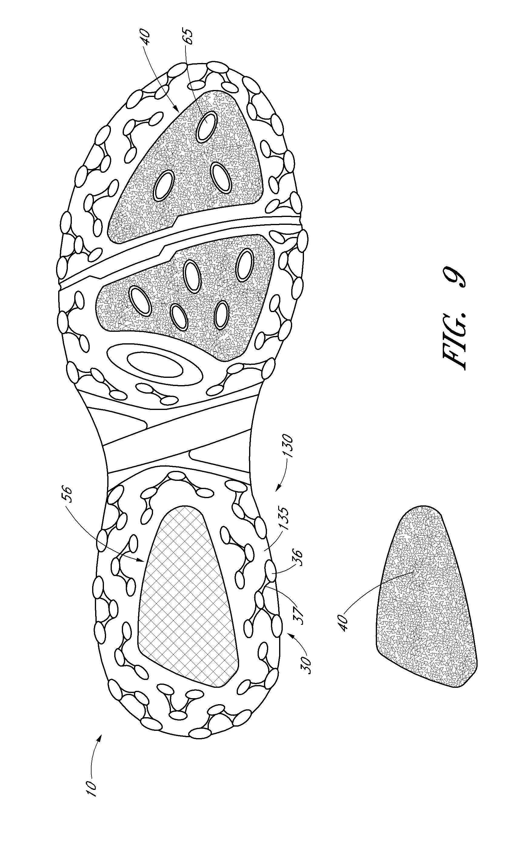
[0033] FIG. 9 is a bottom view of an embodiment of a traction system for a shoe with a replaceable traction portion.
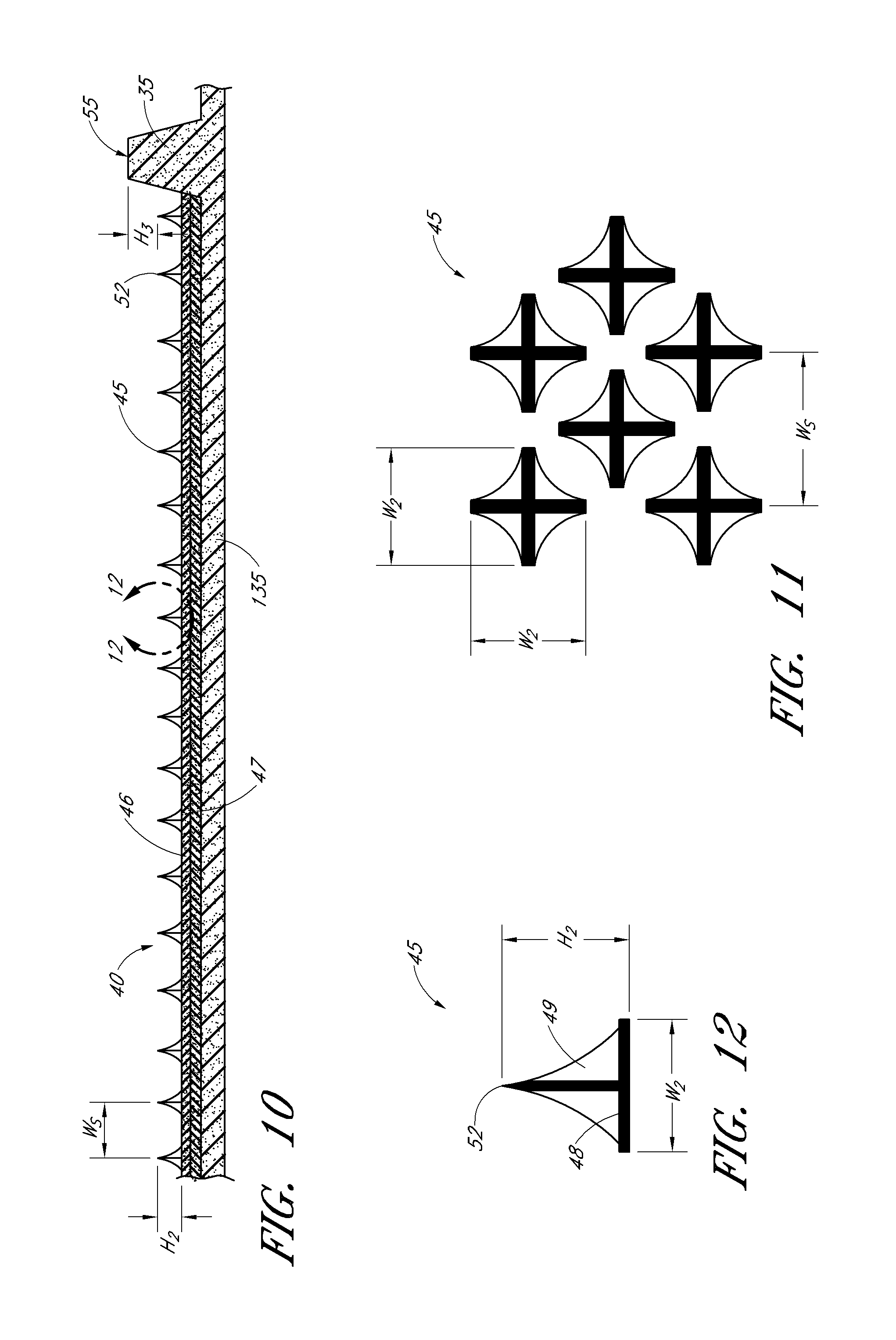
[0034] FIG. 10 is an enlarged side cross-sectional view of an embodiment of a traction portion of a traction system for a shoe taken along lines 10-10 of FIG. 4.
[0035] FIG. 11 is an enlarged bottom view of a plurality of traction elements of the traction portion of FIG. 10.
[0036] FIG. 12 is an enlarged side view of a traction element of the traction portion of FIG. 10.
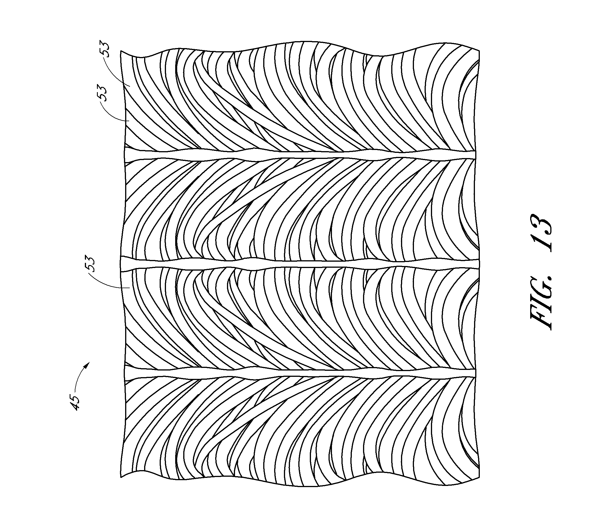
[0037] FIG. 13 is an enlarged side perspective view of an embodiment of an array of traction elements that can be implemented with a traction system for a shoe.
DETAILED DESCRIPTION OF THE PREFERRED EMBODIMENTS
[0038] The present disclosure provides for embodiments of a traction system for an athletic shoe with components to meet the performance requirements of a given activity, and is designed to meet the traction requirements of individuals engaged in said activity. Although embodiments will be discussed in terms of a traction system particularly adapted for athletic shoes, such as golf shoes, to be worn while golfing, it will be understood that the inventions can also be employed with other types of shoes, such as athletic, casual, or other types of sports or non-sports related footwear. Described herein are traction systems for shoes that provide increased traction, durability, and comfort to the user over a number of surfaces of varying textures, contours and hardness. Some embodiments provide increased traction without damaging turf (e.g., of a golf course) or floor surfaces (e.g., of a golf clubhouse).
[0039] As used herein, "anterior" means the front of the person wearing the shoes described herein. "Posterior" means the back of the wearer's body. "Medial" means toward the approximate medial plane or vertical axis of the wearer's body, whereas "lateral" means away from the approximate medial plane or vertical axis of the wearer's body. "Superior" means approximately upwardly towards the upper portion of the shoe, whereas "inferior" means approximately downwardly towards the lower portion of the shoe.
[0040] FIG. 1 is a side partial cross-sectional view of an embodiment of a footwear or shoe 100. Shoe 100 can comprise an upper portion or body 110 attached to a lower portion or sole 120. Upper portion 110 is not limited to the closed-toe embodiment shown, and can comprise any of a number of upper bodies for footwear known in the art or described herein, such as an open-toe (e.g., a sandal, thong, etc.) or other design. Sole 120 can comprise one or more layers of material such as an outsole 130, midsole 140, insole board 150, and/or footbed 160, as is known in the art or described herein. It will be understood that midsole 140 is optional, and/or can be integrally formed with outsole 130. Additionally, as used herein, "coupled" is defined as directly coupled to, or indirectly coupled to (e.g., with one or more intervening layers). For example, a portion of outsole 130 can directly couple to a portion of upper 110. Alternatively or additionally, a portion of outsole 130 can indirectly couple to upper 110, e.g., when a portion of outsole 130 is directly coupled to one or more of layers 140, 150, 160, which are directly coupled to a portion of outsole 130.
[0041] With reference to FIGS. 2 and 3, an embodiment of the present invention can comprise a traction system 10 comprising one or more traction portions (e.g., traction portions 30, 40, described further herein), to provide traction between shoe 100 and a surface. The traction portions can have any of a number of different traction characteristics that can affect the traction between the shoe 100 and an external surface (e.g., turf), and/or the comfort to a wearer of shoe 100. For example, the traction portions described herein can include a plurality of traction elements, such as traction element(s) 35 (for traction portion 30; see, e.g., FIGS. 2-8) and/or traction element(s) 45 (for traction portion 40; see e.g., FIGS. 3 and 10-13), with any of a number of different sizes, materials, shapes, orientations, spacing, density, hardness, or other characteristics to affect the traction and/or comfort of shoe 100, as described further herein.
[0042] The traction portions can form a part of outsole 130 and/or one or more other shoe layers, such as those described above and illustrated in FIG. 1. Referring again to FIGS. 2-3, in the illustrated embodiment, the traction portions 30, 40 form a part of outsole 130, and are attached to a body 135 of outsole 130. Outsole 130 can be coupled to upper portion 110. A peripheral boundary 20 (FIG. 3) can define the general outer perimeter of the upper portion 110 and/or outsole 130. The peripheral boundary 20 can follow a contour that is selected to conform to the overall shape of the foot.
[0043] The upper 110 and/or outsole 130 can have an anterior end 21 at the front or toe portion of the wearer's foot and a posterior end 22 at the rear or heal portion of the wearer's foot. The upper 110 and/or outsole 130 can have a contoured medial side 23 and a contoured lateral side 24 on opposed sides of a plane 500 extending generally longitudinally and in a superior/inferior direction, along the approximate center of shoe 100. As used herein, "plane" does not impart a flat or planar surface, and can be defined by an axis extending in a first dimension that is then extended along a curvilinear path. For example, plane 500 is formed by extending a superior-inferior axis along an approximately central path extending between contoured sides 23, 24. In the embodiment of FIGS. 2 and 3, the traction system 10 is configured to support the right foot of the wearer. A traction system configured to support the left foot would be a mirror image of the midsole shown in FIGS. 2 and 3. For simplicity, only one traction system of a pair will be described in detail herein.
[0044] Continuing to refer to FIGS. 2 and 3, outsole 130 can include a first traction portion 30 and a second traction portion 40, wherein traction portions 30, 40 define a portion of a bottom surface of shoe 100. First and second traction portions 30, 40 can provide shoe 100 with first traction characteristics similar to, or preferably, different from the second traction characteristics. For example, first and second traction portions 30, 40 can provide different levels of traction with respect to each other in different directions and/or on different types of surfaces (e.g., turf, a clubhouse floor, etc.).
[0045] Traction portions 30, 40 can comprise any of a variety of materials with a variety of traction characteristics, and can comprise the same or different materials with respect to each other. Traction portions 30, 40 can comprise one or more of a variety of metals, composites or relatively rigid, molded plastic materials, (e.g., thermoplastics or thermoplastic resins, comprising, for example, polyurethane, polyethylene, nylon, polycarbonate, etc.) and may be substantially transparent, translucent or opaque, or any of a variety of colors. Traction portions 30, 40 can comprise a surface coating or treatment, such as a grain or grit (e.g., silicon carbide, zirconia alumina, ceramic alumina, or any of the aforementioned plastic materials in a grain or grit form, etc.), fiber, sandblasting, and/or other material or treatment that can provide traction. In some embodiments, zirconia and/or ceramic can be implemented for lower cost and to provide similar traction characteristics as, for example, silicon carbide. In some embodiments, a grain or grit comprising alumina can add durability and lower the effects of frictional heat, which can cause premature wear to traction portions 30, 40. In embodiments employing a grain or grit, a larger grit size may provide greater traction performance and longer life, although the size of the grit (e.g. average particle diameter) employed can vary anywhere within a range of approximately 8.4 to approximately 1815 .mu.m. In some embodiments, the grit size can be within a range of approximately 92 to approximately 708 .mu.m. Other grit sizes can also be used, depending on the desired traction characteristic. In an embodiment, at least one of traction portions 30, 40 comprises thermoplastic polyurethane, of a durometer or Shore hardness in the type D scale between a range of about 40 to 95, or more preferably, about 55 to 85, or more preferably, about 70.
[0046] Traction portions 30, 40 can extend across some, most, or substantially the entirety of one or more sides of shoe 100. For example, traction portions 30, 40 can extend across a portion of the bottom or inferior side of shoe 100 (FIG. 3). Traction portions 30, 40 can extend across a portion of one or more additional sides of shoe 100, such as anterior, posterior, medial, or lateral sides, to provide additional traction (FIG. 2).
[0047] Traction portions 30, 40 can be configured to form one or more regions (e.g., sections or subsections) along a side of shoe 100 (e.g., the inferior or bottom side), to provide one or more of a variety of traction and/or comfort characteristics for shoe 100. Such sections or subsections can provide different amounts of traction in one or more directions (e.g., a lateral, medial, anterior, and/or posterior direction, and/or torsional traction around a superior/inferior-extending axis). A section or subsection of traction portion(s) 30, 40 can extend across part, most, or the substantial entirety of the length and/or width of shoe 100, and can be any of a number of different shapes (e.g., an approximate circular, ovular, rectangular, square, ring-like, hourglass-like, or other regular or irregular shape).
[0048] In some embodiments, traction portions 30, 40 can form one or more perimeters or sub-perimeters that can partially or completely surround a corresponding inner or central region formed by the other of traction portions 30, 40. Such embodiments can provide an outer perimeter traction characteristic that is different from an inner region traction characteristic within said perimeter or sub-perimeter. In some such embodiments, the inner region can be free of the traction portion 30, 40 that forms the perimeter or sub-perimeter. For example, a perimeter or sub-perimeter formed with one or more of traction portions 30, 40, can provide increased torsional traction and stability around a superior/inferior axis extending through said perimeter or sub-perimeter. An inner region formed within such a perimeter or sub-perimeter can provide increased lateral, medial, anterior, and/or posterior traction and stability. The one or more perimeters or sub-perimeters of traction portions 30, 40 can approximately follow some, most or substantially the entirety of the contour formed by perimeter 20 (FIG. 3). In some embodiments, traction portions 30, 40 can form sections or subsections with portions that deviate from the contour formed by perimeter 20.
[0049] First traction portion 30 can comprise a forefoot section 31 configured and positioned to support and provide traction for a wearer's forefoot and phalanges, and a heel section 32, configured and positioned to support and provide traction for a wearer's heal. Sections 31 and/or 32 can be configured with any of the shapes described generally herein for traction portion(s) 30, 40. In the illustrated embodiment, sections 31, 32 define a perimeter that can provide additional torsional traction for the forefoot and heel of shoe 100. The perimeters formed by sections 31, 32 can be positioned within perimeter 20, and thus can form sub-perimeters with respect thereto. In some embodiments, sections 31, 32 can be combined, and thus comprise a single loop or perimeter extending along the bottom surface of shoe 100, e.g., a perimeter that substantially follow the contours of perimeter 20.
[0050] In some embodiments, sections 31, 32 can substantially surround some, most or substantially all of one or more corresponding regions (e.g., inner or central regions) or inserts of second traction portion 40. As such, one or more inserts of traction portion 40 can be positioned within one or more perimeters formed by corresponding forefoot section 31 and/or heel section 32 of first traction portion 30. For example, traction portion 40 can be positioned within a single perimeter formed by traction portion 30, e.g., one that substantially follows the contours of perimeter 20. In the illustrated embodiment, second traction portion 40 comprises a heel insert 41 and a forefoot insert 42 configured to be positioned within a perimeter formed by sections 31, 32, respectively, of first traction portion 30. Heel insert 41 can provide additional traction and stability to the heel of shoe 100 (e.g., posterior traction), and forefoot insert 42 can provide additional traction and stability to the forefoot of shoe 100 (e.g., anterior traction).
[0051] The inserts 41, 42 can be configured to cover, and thus provide traction to, a substantial portion of a surface (e.g., the bottom surface) of shoe 100, and preferably, an inner or central region of the bottom surface of shoe 100. In some embodiments, the inner regions or inserts 41, 42 cover a surface on shoe 100 that is free of first traction elements 35. In some embodiments, one or more traction elements 35, or another type of traction element (e.g., traction element 65; FIG. 9) extend from or through a portion of inserts 41 and/or 42. Such embodiments can separate and prevent interference between the differing traction characteristics of traction portions 30 and 40. In some embodiments, second traction portion 40 can cover a range of approximately 10-90% of the bottom of shoe 100, or more preferably, 20-80%, or more preferably, 30-65%. In some embodiments, second traction portion 40 covers at least 25% of the bottom of shoe 100. In some embodiments, second traction portion 40 covers at least 35% of the bottom of the shoe 100. In some embodiments, second traction portion 40 covers approximately 40% of the bottom of the shoe 100.
[0052] It will be understood that the aforementioned regions or sections of traction portions 30, 40, such as insert 41 and/or 42, can include one or more sub-portions or sections to provide additional traction characteristics. Referring to FIG. 3, forefoot insert 42 can comprise a first forefoot insert section 42A and a second forefoot insert section 42B, to provide further control of the traction within a posterior and anterior portion, respectively, of forefoot insert 42. It will be understood that any of a number of combinations of sections and subsections (e.g., perimeters and sub-perimeters) can be employed to provide a variety of different results. For example, heel insert 41, forefoot section 31 and/or heel section 32 can be sub-sectioned into two or more sections, similar to inserts 42A and 42B of forefoot insert 42.
[0053] In embodiments of traction system 10 that include two or more inserts or sections (e.g., forefoot section 31, heel section 32, inserts 41, 42, and/or insert sections 42A, 42B), such inserts or sections can be spaced from one another on opposite sides of one or more planes extending through athletic shoe 100. Inserts 42A, 42B are spaced from one another on opposite sides of a phalangeal medial-lateral plane 501 extending through athletic shoe 100 for illustrative purposes only. For example, the inserts or sections 31, 32, 41, 42, 42A, 42B can be spaced from one another on opposite sides of plane 500, or any other plane extending through the bottom side of shoe 100 (e.g., any other plane extending through the bottom side of shoe 100 and angled with respect to planes 500, 501).
[0054] In embodiments of traction system 10 that include two or more sections forming two or more sub-perimeters, such sub-perimeters can include one or more overlapping or intersecting portions. Thus, although the sub-perimeters formed by forefoot section 31 and heel section 32 of traction portion 30 are shown spaced from each other in a posterior/anterior direction, these sub-perimeters can intersect, connect, and/or overlap in some embodiments.
[0055] Referring to FIGS. 3-6, traction system 10 can comprise one or more wear bars 50 extending from the bottom of shoe 100 (e.g., attached to base 135 of outsole 130). Wear bar 50 can comprise any known or the aforementioned materials described for traction portions 30, 40. In some embodiments, wear bar 50 comprises a material with higher wear properties than the material of traction portion 40.
[0056] Wear bar 50 can extend along a portion of shoe 100, such as along a portion of planes 500, 501, and/or the other aforementioned planes angled with respect to planes 500, 501. Wear bar 50 can extend through some, most, or substantially the entirety of traction portions 30, 40 (e.g., sections 41, 42). Wear bar 50 can extend from a portion of traction portions 30, 40 (e.g., from one or more of the aforementioned perimeters formed by traction portion 30 around traction portions 40). Wear bar 50 can extend along a side of traction portion 40 (e.g., along a portion of one or more of the aforementioned perimeters formed by traction portion 30, or along a portion of perimeter 20 of outsole 130). Wear bar 50 can extend across some, most, or substantially all of the width (e.g., laterally-medially) or length (e.g. anteriorly-posteriorly) of the bottom side of shoe 100. In some embodiments, wear bar 50 can include a bottommost or inferior-most surface 51 that is positioned below, or inferior to, the second traction portion 40, to reduce wear on the second traction portion 40. In use, wear bar 50 can extend, or penetrate a softer material, such as turf, sufficiently that second traction portion 40 will engage and provide traction with the softer material. When shoes 100 are worn on harder material, such as a floor to a clubhouse, wear bar 50 will not extend into or penetrate the material, preventing contact (and thus preventing wear) on second traction portion 40. This allows second traction portion 40 to comprise lower-wear materials that provide greater traction than might otherwise be employed due to shortened life of use. It will be understood that "bar" as used to define wear bar 50 need not define an elongated shape and that wear bar 50 can comprise any of a number of straight or curvilinear elongated or non-elongated shapes suitable to penetrate a softer material without penetrating a harder material, while providing increased wear-resistance with respect to traction portion 40.
[0057] Traction portions 30, 40 can be separately formed and attached to one or more portions of shoe 100 (e.g., outsole 130, body 135 of outsole 130, and/or the other layers shown in FIG. 1) using a variety of attachment methods or engagement elements known or described herein, or can be a solid or unitary component. Examples of engagement and attachment structures and methods that can be employed include one or more adhesive, snaps, hooks, tabs, a press fit, clasps, interference fit, snap fit, slots, grooves, screws, threads, rivets, magnets, hook and loop systems (e.g., Velcro.RTM.), and the like.
[0058] Traction portions 30, 40 can be attached to shoe 100 permanently or semi-permanently. In some embodiments, traction portions 30, 40 can be removably or releasably attached to shoe 100. In some embodiments, first traction portion 30 can comprise a removable stud, spike, lug, or other structure that is removably threaded into corresponding threads in shoe 100, (e.g., body 135 of outsole 130). In some embodiments, second traction portion 40 can comprise a hook and loop system to removably attach portion 40 to shoe 100 (e.g., body 135). Recent developments in hook and loop systems, such as those manufactured by Paiho, located in Taiwan (including, for example Paiho ETN-62 hook and ETB-06 or #1057 loop) have sufficient sheer strength to be used in a shoe traction system. Such sheer strength in a hook and loop system for a shoe traction system was previously unknown and unavailable.
[0059] Removability of portions 30, 40 from the remainder of shoe 100 can allow portions 30, 40 to be removed, for example, to avoid damaging a surface on which shoe 100 is used, to change traction portions 30, 40 with another traction portion with different characteristics (due to different conditions in which shoe 100 is being used), and/or to replace traction portions 30, 40 due to wear. The removability of traction portions 30, 40 with respect to each other can allow one of portions 30, 40 to be removed separately from removal of the other of portions 30, 40, from shoe 100, for example, if one wears more quickly than the other. In some embodiments, one of traction portions 30, 40 (e.g., portion 30) can be integrally formed with or permanently coupled to the outsole base 135, to form a permanent outsole portion, and the other of traction portions 30, 40 (e.g., portion 40), can be releasably attached to the outsole base 135, to form a replaceable outsole portion. An embodiment of a replaceable traction portion insert 40 is shown in FIG. 9, and described further below. An integrally formed or permanently coupled traction portion that would require specialized skill and/or specialized equipment to remove and replace is generally not considered "replaceable" as used herein. That is, activity that would essentially be a reconstruction or rebuilding of the shoe 100 would not fall within the definition of "replaceable." Such constructions would be considered permanently coupled to the shoe 100. Preferably, a replaceable traction portion can be removed and replaced with no tools, common tools or specialized tools that are provided with the shoe 100 or otherwise easily obtainable and with little or no specialized knowledge or skill. That is, preferably, a replaceable traction portion can be removed and replaced by a user of the shoe 100. An example of a replaceable traction portion is one that is peelable by hand under normal use conditions without any special tools, such as with the hook-and-loop fastener arrangement described herein. A traction portion that can be removed and replaced using only common tools (e.g., screw driver, hex key) or a specialized tool (e.g., specialized driver specifically configured to engage or interact with the traction portion or a removable fastener that secures the traction portion to the shoe 100 may also be considered as replaceable.
[0060] FIGS. 7 and 8 are bottom and side views, respectively, of traction element 35. Note that traction element 35 in FIG. 8 is shown in an upside-down orientation with respect to the view shown, for example, in FIG. 2. Traction element 35 be configured in one of any number of shapes that can provide traction, such as, for example, star-shapes, cross-shapes, X-shapes, diamond shapes, circles, triangles, squares, crescents, rectangles, U-shapes, V-shapes, pyramid-shapes, conical shapes, etc. Traction element 35 need not be uniform in cross-section, and may be varied geometrically by thickness, symmetry, and angle of drafting. Additionally, in embodiments with a plurality of traction elements 35, different shapes can be used for different individual traction elements or sets with respect to each other. The geometrical variations of traction element 35 can determine, in part, the traction properties of traction system 10. The number, pattern (e.g., spacing with respect to each other and/or positioning on base 135) of the traction elements 35, 45 can also be varied to provide various traction properties. In some embodiments, traction portion 30 comprises at least 30 traction elements 35.
[0061] In the illustrated embodiment, traction element 35 comprises an approximately elliptical portion or body 36, with one or more optional fins 37 extending from the elliptical portion 36. Fins 37 can provide additional traction (e.g., in one or more additional directions) than an embodiment employing only elliptical body 36. Fins 37 can extend from elliptical portion 36 in a variety of ways. In an embodiment, a pair of fins 37 extends from opposing ends of the elliptical portion. Fins 37 can extend from the elliptical portion approximately collinear with major or minor axes (502, 503, respectively) of the elliptical portion, or can extend at an angle with respect to the major or minor axes of the elliptical portion 36. In an embodiment with the pair of fins extending from the elliptical portion 36, said pair can extend from the same or different sides of an axis extending through the elliptical portion 36. In the illustrated embodiment, the pair of fins 37 extends from the same side of major axis 502 extending through elliptical portion 36.
[0062] The dimensions (e.g., height, width, length, diameter, etc.) of the traction elements 35, 45 can be varied to provide various traction properties. For example, in some embodiments traction element 35 can comprise a height H.sub.1 with a range of about 1 mm to 10 mm, or more preferably, about 2 mm to 8 mm, or more preferably, approximately 4 mm. In some embodiments, traction element 35 comprises a height of less than or equal to about 6 mm. In some embodiments, the height H.sub.1 can be selected based upon the height selected for traction element 45, as described further below.
[0063] In some embodiments, traction element 35 can comprise a length L.sub.1 with a range of about 3 mm to 25 mm, or more preferably, about 5 mm to 15 mm, or more preferably, approximately 10 mm. In some embodiments, traction element 35 can comprise a width W.sub.1 with a range of 3 mm to 15 mm, or more preferably, about 4 mm to 12 mm, or more preferably, approximately 8 mm. In some embodiments, traction element 35 comprises a height of less than or equal to about 10 mm. In some embodiments, traction element 35 comprises at least one of a width and length that is greater than or equal to a width W.sub.2 of traction element 45, described further below. In some embodiments, traction element 35 comprises a width and length that are both greater than a width W.sub.2 of traction element 45. Such embodiments can vary the amount and direction of the traction provided by traction portions 30 and 40 with respect to each other.
[0064] FIG. 10 is an enlarged side cross-sectional view of an embodiment of traction portion 40 of traction system 10 taken along lines 10-10 of FIG. 4. FIG. 11 is an enlarged bottom view of a plurality of traction elements 45 of the traction portion 40 of FIG. 10. FIG. 12 is an enlarged side view of traction element 45 of the traction portion 40 of FIG. 10. Note that traction portion 40 and traction element 45 in FIGS. 10 and 12, respectively, are shown in an upside-down orientation with respect to the view shown, for example, in FIG. 4.
[0065] Traction portion 40 can comprise one or more optional layers to facilitate its attachment (e.g., releasable attachment) to (and from) another portion of shoe 100 (e.g., outsole base 135) (FIGS. 2, 3). In the illustrated embodiment, portion 40 comprises a support layer 46 to provide support on one of its sides to a plurality of traction elements 45. An attachment layer 47 can be attached to the opposing side of support layer 46, to attach traction portion 40 to base 135. Attachment layer 47 can comprise one or more of the aforementioned attachment elements and methods, and preferably comprises at least one component of a hook/loop attachment system, with the mating component attached to a corresponding portion of base 135 (e.g., within an optional recess 56 of body 135, described further below; FIG. 9). Support layer 46 can comprise a material with sufficient rigidity to support traction elements 45 and to attach to base 135, and sufficient flexibility to provide comfort to the user when worn, such as plastic, sheet metal, cloth, mesh, resin, or other suitable materials. In some embodiments, support layer 46 and/or attachment layer 47 comprise a water-resistant or waterproof, durable, and self-cleaning material. It will be understood that the aforementioned layers 46, 47 are optional, and that traction elements 45 can be attached directly or indirectly to outsole 130 (e.g., base 135), or the other layers shown in FIG. 1. Additionally, the use of "layer" for features 46, 47 does not necessarily impart a continuous structure, and layers 46 and 47 can be continuous or discontinuous structures.
[0066] Traction elements 45 can comprise any of a variety of shapes, patterns, quantities, spacing, dimensions, and other configurations, including those aforementioned for traction element 35 (FIGS. 2-8), and vice-versa. In some embodiments, traction elements 45 can comprise a plurality of grains (e.g., abrasive grains). In some embodiments, traction elements 45 can comprise a plurality of fibers 53, such as those shown in FIG. 13. As shown in FIG. 13, the fibers 53 can be organized substantially in rows and/or columns; however, in other arrangements, the fibers 53 can be organized in other patterns or can be random. In some embodiments, traction elements 45 can comprise a conical or pyramid-shaped (e.g., with three or more sides) spike. Referring again to FIGS. 10-12, in the illustrated embodiment, traction elements 45 can comprise one or more sides 49 extending from optional layer 46, outsole 130, or the other layers of shoe 100 shown in FIG. 1. In the illustrated embodiment, sides 49 extend from an optional base 48 that can be attached to support layer 46, or the other layers of shoe 100. Sides 49 can extend in a tapered manner to form an optional point 52 to provide additional traction to traction element 45. It will be understood that traction elements 45 can comprise a cylindrical, rectangular, frustro-conical, frustro-pyramidal, or other shape that has a substantially flat or blunt tip, while still providing the desired traction characteristics.
[0067] The dimensions and spacing of elements 45 can be varied to provide a variety of traction characteristics. The height H.sub.2 of element 45 can fall within a range of approximately 1 mm to 10 mm, or more preferably, 2 mm to 5 mm, or more preferably, approximately 3 mm. The width W.sub.2 of elements 45 can fall within a similar range. Although elements 45 are shown with an approximately symmetric shape, elements 45 can be asymmetrically shaped with different widths on its two or more sides. Additionally, traction portion 40 can comprise traction elements 45 of different shapes and/or sizes with respect to each other and/or traction elements 35.
[0068] Referring to FIGS. 4, 8, 10 and 12, in some embodiments, the height H.sub.1 of traction elements 35 and the height H.sub.2 of elements 45 can be configured with respect to each other, and/or with respect to the attachment of traction portions 30, 40 to base 135 (FIG. 4). For example, the second traction elements 45 (e.g., their bottommost, inferior-most surface, or point 52) can be configured to be superior to (e.g., recessed above) the bottommost or inferior-most surface 55 of the traction elements 35 by a height H.sub.3 (FIG. 10). Height H.sub.3 can be provided, for example, by configuring the height H.sub.1 of traction elements 35 to be greater than the height H.sub.2 of elements 45, as shown. Additionally or alternatively, height H.sub.3 can be provided by configuring the engagement of traction elements 35, 45 to base 135 in a superior and/or inferior direction with respect to each other. Such embodiments can reduce the wear on traction elements 45 while traction elements 35 are engaged with a surface, such as turf. In some embodiments, the height H.sub.3 can fall within a range of approximately 0.25-3 mm, or more preferably, 0.25-1.5 mm, or more preferably, 1 mm.
[0069] Referring again to FIGS. 10-12, the spacing width W.sub.s of adjacent elements 45 can fall within a range of approximately 1 mm to 10 mm, or more preferably, 2 mm to 8 mm, or more preferably, approximately 5 mm. A plurality of elements 45 can be positioned in two or more aligned or offset rows and/or columns, such that second traction portion 40 can comprise various 2 or 3-dimensional arrays or matrices of elements 45. Similar arrangements can be employed with elements 35 of first traction portion 30. Moreover, although elements 45 are shown approximately evenly spaced with respect to each other, elements 45 can be spaced at different intervals with respect to each other and/or traction elements 35.
[0070] Referring again to FIG. 3, traction system 10 can comprise adjacent traction elements 35A and 35B, each comprising fins 37A and 37B, respectively. Traction elements 35A and 35B, and fins 37A, 37B can be similar to those embodiments of traction elements 35 and fins 73 described elsewhere herein. One difference is that the embodiment of FIG. 3 includes the pair of fins 37A of traction element 35A extending from the elliptical portion 36 of element 35A towards the adjacent second traction element 35B, and the pair of fins 37B of traction element 35B extend from the elliptical portion 36 of element 35B towards the first traction element 35A. In another embodiment, the pair of fins 37A of traction element 35A extends from the elliptical portion 36 of element 35A away from the adjacent second traction element 35B, and the pair of fins 37B of traction element 35B extend from the elliptical portion 36 of element 35B away from the first traction element 35A.
[0071] FIG. 9 is a bottom view of an embodiment of a traction system for a shoe with a replaceable traction portion 40 that can be attached to body 135 of outsole 130. In some embodiments, traction portion 40 can be inserted into the optional recess 56 extending into body 135. FIG. 9 also includes an additional optional traction portion comprising optional traction elements 65 that can extend through portions of traction portion 40. As such, traction portion 40 can overlap and/or surround a traction element 65. Traction element 65 can comprise similar shapes, structures, materials, etc., as described herein for elements 35, 45. FIG. 9 also shows additional embodiments of traction portion 30, in which two or more bodies 36 are connected by one or more cross-members or fins 37 at a variety of different angles and configurations, to provide various traction characteristics.
[0072] As described above, the traction portion 40 may be replaceable such that a worn traction portion 40 can be replaced or to change the traction characteristics of the shoe 100. One or more sections of the traction portion 40 may be sold separately from the shoes 100 to facilitate such replacement. These replacement traction portions can be configured to be releasably secured to the shoe such that the replacement traction portion defines a portion of the bottom surface of the shoe. In one arrangement, the replacement traction portion includes one of a hook portion and a loop portion of a hook-and-loop fastener to complement the other of the hook portion and the loop portion provided on the shoe. In one arrangement, the replacement traction portion is substantially U-shaped. The replacement traction portion may be provided in a kit containing a set of replacement traction portions configured to replace some or all of the original traction portions of a pair of shoes. In one arrangement, the kit may contain three replacement traction portions for each one of the pair of shoes. Each of the three replacement portions may be substantially U-shaped.
[0073] Although embodiments of these inventions have been disclosed in the context of certain examples, it will be understood by those skilled in the art that the present inventions extend beyond the specifically disclosed embodiments to other alternative embodiments and/or uses of the inventions and obvious modifications and equivalents thereof. In addition, while several variations of the inventions have been shown and described in detail, other modifications, which are within the scope of these inventions, will be readily apparent to those of skill in the art based upon this disclosure. It is also contemplated that various combinations or sub-combinations of the specific features and aspects of the embodiments may be made and still fall within the scope of the inventions. It should be understood that various features and aspects of the disclosed embodiments can be combined with or substituted for one another in order to form varying modes of the disclosed inventions. Additionally, it will be understood that variations in the shapes and/or patterns of the traction system and its components described herein can provide a similar functional result.
* * * * *
D00000
D00001
D00002
D00003
D00004
D00005
D00006
XML
uspto.report is an independent third-party trademark research tool that is not affiliated, endorsed, or sponsored by the United States Patent and Trademark Office (USPTO) or any other governmental organization. The information provided by uspto.report is based on publicly available data at the time of writing and is intended for informational purposes only.
While we strive to provide accurate and up-to-date information, we do not guarantee the accuracy, completeness, reliability, or suitability of the information displayed on this site. The use of this site is at your own risk. Any reliance you place on such information is therefore strictly at your own risk.
All official trademark data, including owner information, should be verified by visiting the official USPTO website at www.uspto.gov. This site is not intended to replace professional legal advice and should not be used as a substitute for consulting with a legal professional who is knowledgeable about trademark law.