Garment Including An Abrasion Resistant Fabric
Dieffenbacher; Jason Wayne
U.S. patent application number 13/166026 was filed with the patent office on 2012-12-27 for garment including an abrasion resistant fabric. This patent application is currently assigned to Jason Wayne Dieffenbacher. Invention is credited to Jason Wayne Dieffenbacher.
| Application Number | 20120324618 13/166026 |
| Document ID | / |
| Family ID | 46466854 |
| Filed Date | 2012-12-27 |


| United States Patent Application | 20120324618 |
| Kind Code | A1 |
| Dieffenbacher; Jason Wayne | December 27, 2012 |
GARMENT INCLUDING AN ABRASION RESISTANT FABRIC
Abstract
An abrasion-resistant garment may include a first fabric layer with a first recovery property and a first direction, and a second fabric layer with a second recovery property and a second direction. The first recovery property is greater than the second recovery property. The second fabric layer is disposed on the first fabric layer in a predetermined orientation of the first direction and second direction to provide enhanced sliding of the second fabric layer along the first fabric layer.
| Inventors: | Dieffenbacher; Jason Wayne; (Nashua, NH) |
| Assignee: | Jason Wayne Dieffenbacher Nashua NH |
| Family ID: | 46466854 |
| Appl. No.: | 13/166026 |
| Filed: | June 22, 2011 |
| Current U.S. Class: | 2/93 ; 2/102; 2/69 |
| Current CPC Class: | A41D 31/245 20190201; A41H 27/00 20130101; A41D 13/0593 20130101; A41D 13/0575 20130101; A41D 1/084 20130101; A41D 1/067 20130101 |
| Class at Publication: | 2/93 ; 2/69; 2/102 |
| International Class: | A41D 1/00 20060101 A41D001/00; A41D 1/04 20060101 A41D001/04; A41B 9/00 20060101 A41B009/00; A41D 1/06 20060101 A41D001/06; A41D 19/00 20060101 A41D019/00; A43B 17/00 20060101 A43B017/00; A41D 1/02 20060101 A41D001/02; A41B 1/00 20060101 A41B001/00 |
Claims
1. An abrasion-resistant garment comprising: a garment body including: a first fabric layer having a first recovery property and a first direction; and a second fabric layer having a second recovery property and a second direction, wherein the first recovery property is greater than the second recovery property; wherein the second fabric layer is disposed on the first fabric layer in a predetermined orientation of the first direction and the second direction that provides enhanced sliding of the second fabric layer along the first fabric layer.
2. The abrasion-resistant garment of claim 1, wherein a coefficient of friction between the first fabric layer and second fabric layer is between 0.15-0.5.
3. The abrasion-resistant garment of claim 1, wherein a coefficient of friction between the first fabric layer and second fabric layer is between 0.15-0.6.
4. The abrasion-resistant garment of claim 1, wherein the predetermined orientation of the first and second directions is defined by an angle of approximately 60.degree. to 90.degree. between the first and second direction.
5. The abrasion-resistant garment of claim 1, wherein the predetermined orientation of the first and second directions is defined by an angle of approximately 45.degree. to 90.degree. between the first and second direction.
6. The abrasion-resistant garment of claim 1, wherein the first recovery property is substantially between 5% to 230% greater than the second recovery property.
7. The abrasion-resistant garment of claim 1, wherein the first recovery property is substantially between 10% to 230% greater than the second recovery property.
8. The abrasion-resistant garment of claim 1, wherein the first recovery property is substantially between 15% to 230% greater than the second recovery property.
9. The abrasion-resistant garment of claim 1, wherein the first recovery property is substantially between 20% to 230% greater than the second recovery property.
10. The abrasion-resistant garment of claim 1, wherein the first fabric layer is an inner layer and the second fabric layer is an outer layer.
11. The abrasion-resistant garment of claim 1, wherein the first and second fabric layers are provided at one or more high risk areas of the garment.
12. The abrasion-resistant garment of claim 1, wherein the garment is selected from a group consisting of a shirt, jersey, jacket, vest, arm warmer, short, pants, tight, knicker, leg warmer, knee warmer, knee brace, sock, glove, baseball sliding short, undergarment, and chap.
13. An abrasion-resistant garment comprising: a garment body including: a first fabric layer with a first fabric layer portion having a first direction; and a second fabric layer with a second fabric layer portion having a second direction; wherein an area defined by the second fabric layer portion is greater than an area defined by the first fabric layer portion by 5% to 30%, and the second layer fabric portion is disposed on the first fabric layer portion in a predetermined orientation of the first direction and the second direction that provides enhanced sliding of the second fabric layer portion along the first fabric layer portion.
14. The abrasion-resistant garment of claim 13, wherein the area defined by the second fabric layer portion is greater than the area defined by the first fabric layer portion by 5% to 15%.
15. The abrasion-resistant garment of claim 13, wherein a coefficient of friction between the first fabric layer and second fabric layer is between 0.15-0.5.
16. The abrasion-resistant garment of claim 13, wherein a coefficient of friction between the first fabric layer and second fabric layer is between 0.15-0.6.
17. The abrasion-resistant garment of claim 13, wherein the predetermined orientation of the first and second directions is defined by an angle of approximately 60.degree. to 90.degree. between the first and second direction.
18. The abrasion-resistant garment of claim 13, wherein the predetermined orientation of the first and second directions is defined by an angle of approximately 45.degree. to 90.degree. between the first and second direction.
19. The abrasion-resistant garment of claim 13, wherein the first fabric layer is an inner layer and the second fabric layer is an outer layer.
20. The abrasion-resistant garment of claim 13, wherein the first and second fabric layers are provided at one or more high risk areas of the garment.
21. The abrasion-resistant garment of claim 13, wherein the garment is selected from a group consisting of a shirt, jersey, jacket, vest, arm warmer, short, pants, tight, knicker, leg warmer, knee warmer, knee brace, sock, glove, baseball sliding short, undergarment, and chap.
22. An abrasion-resistant garment comprising: a garment body including: a first fabric layer with a first direction; and a second fabric layer with a second direction, wherein the second fabric layer is disposed on the first fabric layer in a predetermined orientation of the first direction and the second direction that provides enhanced sliding of the second fabric layer along the first fabric layer, and wherein the first fabric layer is subject to a greater tensile load than the second fabric layer when the garment is in a fitted state.
23. The abrasion-resistant garment of claim 22, wherein a coefficient of friction between the first fabric layer and second fabric layer is between 0.15-0.5.
24. The abrasion-resistant garment of claim 22, wherein a coefficient of friction between the first fabric layer and second fabric layer is between 0.15-0.6.
25. The abrasion-resistant garment of claim 22, wherein the predetermined orientation of the first and second directions is defined by an angle of approximately 60.degree. to 90.degree. between the first and second direction.
26. The abrasion-resistant garment of claim 22, wherein the predetermined orientation of the first and second directions is defined by an angle of approximately 45.degree. to 90.degree. between the first and second direction.
27. The abrasion-resistant garment of claim 22, wherein the tensile load of the first fabric layer is substantially between 5% to 230% greater than the tensile load in the second fabric layer.
28. The abrasion-resistant garment of claim 22, wherein the tensile load of the first fabric layer is substantially between 10% to 230% greater than the tensile load in the second fabric layer.
29. The abrasion-resistant garment of claim 22, wherein the tensile load of the first fabric layer is substantially between 15% to 230% greater than the tensile load in the second fabric layer.
30. The abrasion-resistant garment of claim 22, wherein the tensile load of the first fabric layer is substantially between 20% to 230% greater than the tensile load in the second fabric layer.
31. The abrasion-resistant garment of claim 22, wherein the first fabric layer is an inner layer and the second fabric layer is an outer layer.
32. The abrasion-resistant garment of claim 22, wherein the first and second fabric layers are provided at one or more high risk areas of the garment.
33. The abrasion-resistant garment of claim 22, wherein the garment is selected from a group consisting of a shirt, jersey, jacket, vest, arm warmer, short, pants, tight, knicker, leg warmer, knee warmer, knee brace, sock, glove, baseball sliding short, undergarment, and chap.
34. An abrasion-resistant garment, comprising: a garment body including a pocket having a first pocket fabric layer with a first direction; and a pad including a second pad fabric layer with a second direction, the pad receivable in the pocket; wherein the pad is disposable in the pocket in a predetermined orientation of the first direction and the second direction that provides enhanced sliding of the pad relative to the first pocket fabric layer.
35. The abrasion-resistant garment of claim 34, wherein a coefficient of friction between the first pocket fabric layer and second pad fabric layer is between 0.15-0.5.
36. The abrasion-resistant garment of claim 34, wherein a coefficient of friction between the first pocket fabric layer and second pad fabric layer is between 0.15-0.6.
37. The abrasion-resistant garment of claim 34, wherein the predetermined orientation of the first direction and second direction is defined by an angle of approximately 60.degree. to 90.degree. between the first direction and second direction.
38. The abrasion-resistant garment of claim 34, wherein the predetermined orientation of the first direction and second direction is defined by an angle of approximately 45.degree. to 90.degree. between the first direction and second direction.
39. The abrasion-resistant garment of claim 34, wherein the garment body further includes in localized areas, or substantially throughout the garment body, a first fabric layer having a first fabric layer direction, and a second fabric layer having a second fabric layer direction, wherein the second fabric layer is disposed on the first fabric layer with a predetermined orientation of the second fabric layer direction and the first fabric layer direction to provide enhanced sliding of the second fabric layer along the first fabric layer.
40. The abrasion-resistant garment of claim 34, wherein the garment body further includes in localized areas, or substantially throughout the garment body, a first fabric layer having a first recovery property and a second fabric layer having a second recovery property, wherein the second fabric layer is disposed on the first fabric layer and the first recovery property is greater than the second recovery property.
41. The abrasion-resistant garment of claim 34, wherein the garment is selected from a group consisting of a shirt, jersey, jacket, vest, arm warmer, short, pants, tight, knicker, leg warmer, knee warmer, knee brace, sock, glove, baseball sliding short, undergarment, and chap.
Description
FIELD
[0001] Garment including an abrasion resistant fabric.
BACKGROUND
[0002] Bicycling has seen a recent surge in popularity, both in terms of recreational activity and interest in competitive events. However, bicycling carries an inherent risk of crashes and falls. Recreational riders can commonly reach speeds in excess of 30 miles per hour. During competitive races these speeds may even exceed 60 miles per hour. When a crash occurs serious abrasions and lacerations may occur to the rider. Especially high risk areas for abrasions and lacerations during a crash include the upper and lower back, shoulders, upper and lower arms, knees, buttocks, outer hips, and outer thighs. These abrasions and lacerations have been termed "road rash" and are generally accepted as an inherent part of the sport.
[0003] It has become common practice to wear helmets to reduce head injuries both during recreational and competitive bike riding. Their effectiveness in reducing the number and severity of head injuries is well documented. Similar protective clothing is desirable to protect against abrasions and lacerations of the body during an energetic impact with the riding surface. Certain protective bicycling apparel uses patches of high strength materials, such as Kevlar, to simply act as a shield against abrasion with the riding surface.
SUMMARY
[0004] The inventor has recognized and appreciated a need for providing a garment, as well as other gear, that offers improved protection from abrasions and lacerations during impacts against a surface, such as may be experienced during a bicycle crash. While the invention is disclosed specifically in connection with bicycling apparel, other apparel arrangements are contemplated as are other types of protective gear.
[0005] In one exemplary embodiment, an abrasion-resistant garment includes a garment body having a first fabric layer with a first recovery property and a first direction, and a second fabric layer with a second recovery property and a second direction. The first recovery property is greater than the second recovery property. The second fabric layer is disposed on the first fabric layer in a predetermined orientation of the first direction and the second direction that provides enhanced sliding of the second fabric layer along the first fabric layer. The garment body may be formed substantially of the first and second fabric layers, or the first and second fabric layers may be provided at localized areas of the garment (e.g., high risk or abrasion prone areas).
[0006] In another exemplary embodiment, an abrasion-resistant garment includes a garment body having a first fabric layer with a first fabric layer portion having a first direction, and a second fabric layer with a second fabric layer portion having a second direction. The second fabric layer portion is disposed on the first fabric layer portion. The area of the second fabric layer portion is greater than the area of the first fabric layer portion by 5% to 30%. The second fabric layer portion is disposed on the first fabric layer portion in a predetermined orientation of the first direction and the second direction that provides enhanced sliding of the second fabric layer portion along the first fabric layer portion. The garment body may be formed substantially of the first and second fabric layers, or the first and second fabric layers may be provided at localized areas of the garment (e.g., high risk or abrasion prone areas).
[0007] In a further exemplary embodiment, an abrasion-resistant garment includes a garment body having a first fabric layer with a first direction, and a second fabric layer with a second direction. The second fabric layer is disposed on the first fabric layer in a predetermined orientation of the first direction and the second direction that provides enhanced sliding of the second fabric layer along the first fabric layer. The first fabric layer is subject to a greater tensile load than the second fabric layer when the garment is in a fitted state. The garment body may be formed substantially of the first and second fabric layers, or the first and second fabric layers may be provided at localized areas of the garment (e.g., high risk or abrasion prone areas).
[0008] In another exemplary embodiment, an abrasion-resistant garment includes a garment body having a pocket with a first pocket fabric layer and a first direction. A pad includes a second pad fabric layer with a second direction, the pad being receivable in the pocket with a predetermined orientation of the first direction and the second direction to provide an enhanced sliding of the pad relative to the first pocket fabric layer. The garment body may include first and second fabric layers with the direction of such first and second fabric layers oriented to provide enhanced sliding of the second fabric layer relative to the first fabric layer. The garment body may alternatively, or in addition, include a first fabric layer with a first recovery property and a second fabric layer with a second recovery property, wherein the first recovery property is greater than the second recovery property. The garment body may be formed substantially of the first and second fabric layers, or the first and second fabric layers may be provided at localized areas of the garment (e.g., high risk or abrasion prone areas).
[0009] It should be appreciated that all combinations of the foregoing concepts and additional concepts discussed in greater detail below (provided such concepts are not mutually inconsistent) are contemplated as being part of the inventive subject matter disclosed herein. In particular, all combinations of claimed subject matter appearing at the end of this disclosure are contemplated as being part of the inventive subject matter disclosed herein.
[0010] The foregoing and other aspects, embodiments, and features of the present teachings can be more fully understood from the following description in conjunction with the accompanying drawings.
BRIEF DESCRIPTION OF THE DRAWINGS
[0011] The accompanying drawings are not intended to be drawn to scale. In the drawings, each identical or nearly identical component that is illustrated in various figures may be represented by a like numeral. For purposes of clarity, not every component may be labeled in every drawing. Various embodiments of the invention will now be described, by way of example, with reference to the accompanying drawings, in which:
[0012] FIG. 1 is a schematic perspective view of two fabric layers oriented in a predetermined enhanced sliding relationship;
[0013] FIG. 2 is a schematic perspective view of a two layer abrasion resistant fabric;
[0014] FIG. 3 is a schematic perspective view of an abrasion resistant fabric integrated into a larger base fabric layer;
[0015] FIG. 4 is a schematic perspective view of an abrasion resistant fabric with a first and second layer having different areas;
[0016] FIG. 5 is an exemplary representation of a shear force being applied to loose outer and inner fabric layers disposed on skin;
[0017] FIG. 6 is an exemplary representation of a shear force being applied to taut outer and inner fabric layers disposed on skin;
[0018] FIG. 7 is an exemplary representation of a shear force being applied to a relatively loose outer fabric layer and a taut inner fabric layer disposed on skin;
[0019] FIG. 8 is an exemplary representation of the compression applied by the first and second fabric layers;
[0020] FIG. 9 is an exemplary representation of the different tensile loading of the outer and inner fabric layers;
[0021] FIG. 10a is a schematic perspective view of a dynamic friction testing setup;
[0022] FIG. 10b is a schematic perspective view of a dynamic friction testing setup;
[0023] FIG. 11 is a schematic perspective view of an abrasion testing setup;
[0024] FIG. 12 is a schematic front view of a jersey incorporating abrasion resistant fabric in localized high risk areas;
[0025] FIG. 13 is a schematic back view of a jersey incorporating abrasion resistant fabric in localized high risk areas;
[0026] FIG. 14 is a schematic perspective view of an arm warmer incorporating abrasion resistant fabric in localized high risk areas;
[0027] FIG. 15 is a schematic perspective view of a legging incorporating abrasion resistant fabric in localized high risk areas;
[0028] FIG. 16 is a schematic top view of a tube like garment incorporating abrasion resistant fabric;
[0029] FIG. 17 is a schematic end view of the tube like garment presented in FIG. 16 incorporating a single seam;
[0030] FIG. 18 is a schematic end view of the tube like garment presented in FIG. 16 incorporating two seams;
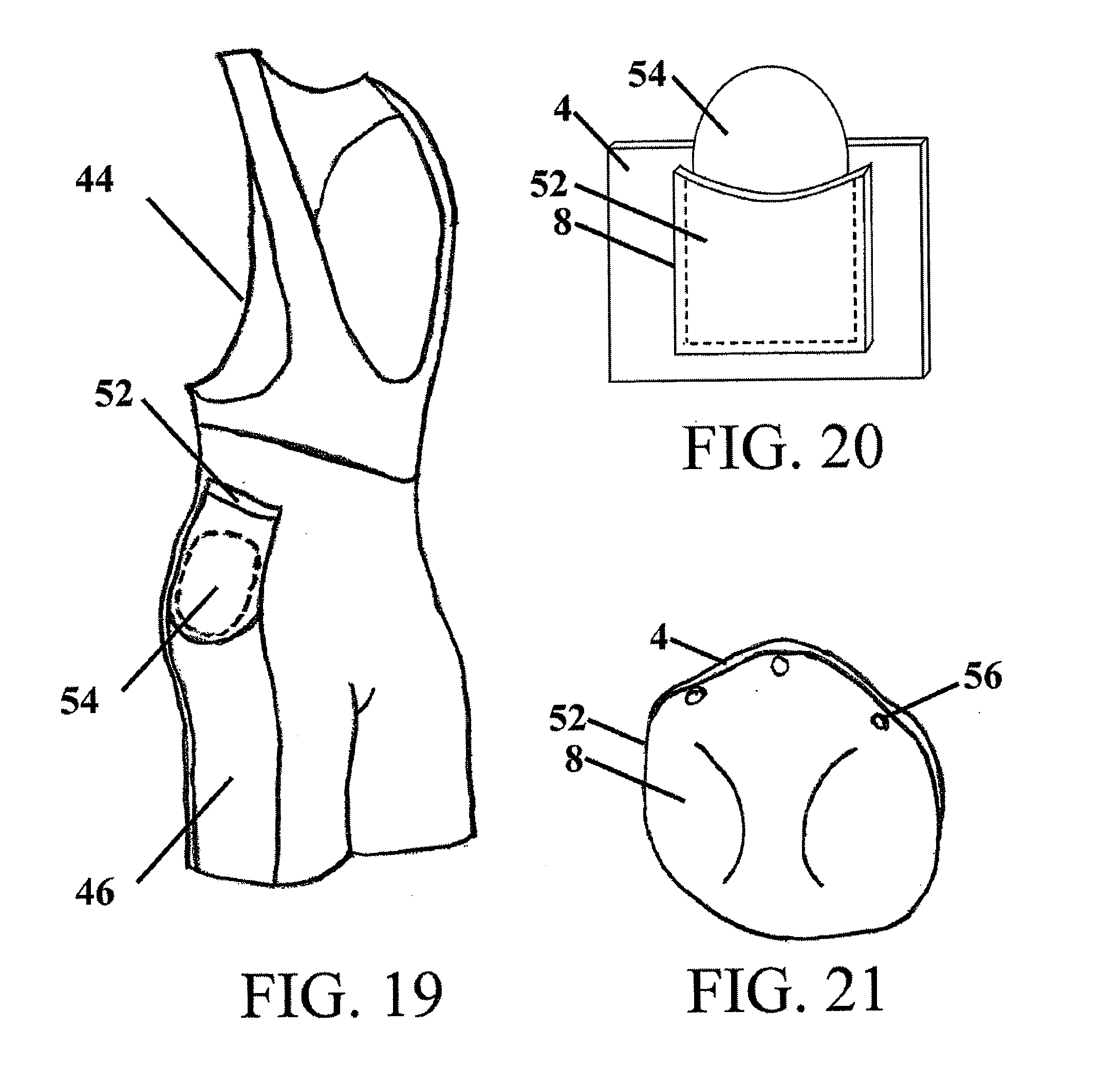
[0031] FIG. 19 is a schematic perspective view of a cycling bib incorporating abrasion resistant fabric and a pocket for an additional pad;
[0032] FIG. 20 is a schematic perspective view of a pad being placed into a pocket in the abrasion resistant fabric; and
[0033] FIG. 21 is a schematic perspective view of a pocket formed by the abrasion resistant fabric.
DETAILED DESCRIPTION
[0034] It should be understood that aspects of the invention are described herein with reference to the figures, which show illustrative embodiments in accordance with aspects of the invention. The embodiments described herein are not necessarily intended to show all aspects of the invention, but rather are used to describe a few illustrative embodiments. Thus, aspects of the invention are not intended to be construed narrowly in view of the illustrative embodiments. It should be appreciated, then, that the various concepts and embodiments introduced above and those discussed in greater detail below may be implemented in any of numerous ways, as the disclosed concepts and embodiments are not limited to any particular manner of implementation. In addition, it should be understood that aspects of the invention may be used alone or in any suitable combination with other aspects of the invention.
[0035] An abrasion resistant fabric for use in a garment and other applications may include a plurality of fabric layers with at least a first inner fabric layer and a second outer fabric layer. Each of the fabric layers may be made from a knitted material, woven material, non-woven material, other fabric constructions, and combinations of any of the forgoing. The direction of each of the at least two fabric layers may have a predetermined orientation to provide enhanced sliding of the second outer fabric layer. When in the predetermined orientation, the coefficient of friction between the layers is substantially reduced in comparison to at least one other orientation and the outer layer is able to more freely slide. In one embodiment, the inner fabric layer of the abrasion resistant fabric may be tensioned to a greater extent and/or provide a greater amount of compression as compared to the outer fabric layer. Without wishing to be bound by theory, a more taut inner fabric layer may permit the inner fabric layer to remain in fixed contact with the underlying skin. The taut inner fabric layer may also provide a smooth regular surface for the adjacent outer fabric layer to slide upon. In addition, the taut inner fabric layer may prevent bunching and/or misorientation of the two layers both of which may result in increased friction and/or binding between the layers. During an impact or crash, the movement of the outer fabric layer over the inner fabric layer, and the reduced coefficient of friction between them, may reduce the transmission of a shear force from the outer fabric layer to the inner fabric layer in contact with the underlying skin.
[0036] In certain embodiments, the abrasion resistant fabric may be incorporated into a garment at high risk and/or abrasion prone areas. Without limitation, the abrasion resistant fabric may be placed at one or more of the following areas: the upper back, lower back, shoulder, upper arm, lower arm, knee, buttock, outer hip, and outer thigh. In one embodiment, patches of the abrasion resistant fabric may be applied in, or to, a base garment. Alternatively, the garment may be made entirely from the abrasion resistant fabric. Possible garments that may incorporate, or be substantially formed of, the abrasion resistant fabric include, but are not limited to: a shirt, jersey, jacket, vest, arm warmer, short, pants, tight, knicker, leg warmer, knee warmer, knee brace, sock, glove, baseball sliding short, undergarment, and chap. Where desired, the individual layers of the abrasion resistant fabric may be selected to provide various properties of breathability, wicking, and/or moisture removal. The fabric layers may also further include high strength fibers to provide additional abrasion resistance.
[0037] Turning now to the figures, several possible embodiments are described in further detail.
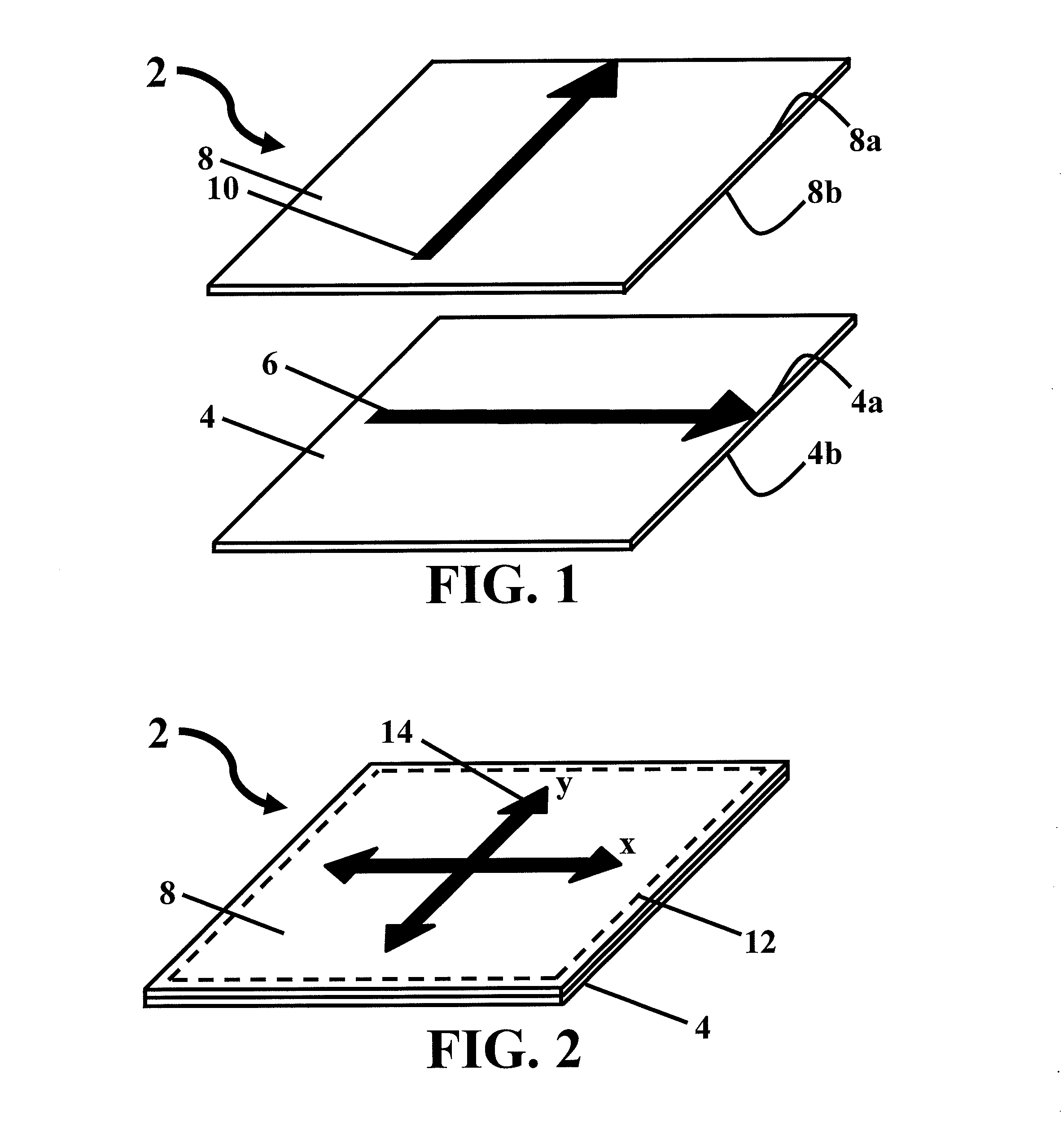
[0038] An abrasion resistant fabric 2 may have a first inner fabric layer 4 and a second outer fabric layer 8, with the second fabric layer disposed over and, as shown in FIG. 1, on the first fabric layer. The abrasion resistant fabric may include additional fabric layers, such that one or more fabric layers are added beneath the first fabric layer, above the second fabric layer, or between the first and second fabric layers. A "direction" of a fabric is a well known term in the textile arts. For example, warp yarns define a direction of a woven fabric and rows of a knit define a direction of a knit fabric. The first inner fabric layer 4 has a first direction 6, indicated by the arrow. The second outer fabric layer 8 has a second direction 10, indicated by the second arrow. The fabric layers may be oriented in a predetermined enhanced sliding relationship to reduce the coefficient of friction between the fabric layers 4 and 8. Reducing the coefficient of friction between the fabric layers 4 and 8 may lower the amount of transmitted shear force to the underlying skin during a crash. In the depicted embodiment, the first and second directions 6 and 10 may be substantially oriented at 90.degree. relative to one another. In other embodiments, the direction of one layer may be oriented substantially between 60.degree. to 90.degree. with respect to the other layer. In another embodiment, the direction of one layer may be oriented substantially between 45.degree. to 90.degree. with respect to the other layer. In some embodiments, the coefficient of friction between fabric layers 4 and 8 may be anisotropic with regards to a clockwise versus counter clockwise orientation (i.e. +90.degree. vs. -90.degree.). Therefore, it may be desirable to determine an enhanced orientation of the directions of the two fabric layers and to dispose the second fabric layer on the first fabric layer in such a predetermined enhanced directional orientation.
[0039] Each fabric layer of abrasion resistant fabric 2 may have a right side, 4a and 8a, intended to face outwards and a wrong side, 4b and 8b, intended to face inwards toward the skin of an individual. Some fabric properties of engineered fabrics, such as wicking and moisture removal, may only function properly when the fabric is arranged with the right side facing outwards. The second fabric layer 8 may be disposed on top of the first fabric layer 4 with the wrong side 8b of the second fabric layer 8 in contact with the right side 4a of the first fabric layer 4.
[0040] In one embodiment, one or both of the fabric layers may be configured with desired wicking and/or moisture removal properties. In the just mentioned embodiment, and/or in other embodiments, the outer fabric layer 8 may be made from a high stretch material and/or have a smooth regular surface. Without wishing to be bound by theory, it is believed that a high stretch material with a smooth regular outer surface may be less likely to tear or shred during a crash. In certain embodiments, the outer fabric layer 8 may be formed of, or include, high strength fibers, providing additional abrasion resistance. In a further embodiment, the inner fabric layer 4 may have a smooth surface and may be made of a high thread count material. In one embodiment, a high thread count material may be 36-gauge or greater. Without wishing to be bound by theory, the coefficient of friction between the layers may be inversely related to the thread count of the materials. Therefore, in some instances higher thread count materials may exhibit correspondingly lower coefficients of friction. In addition to the above, the fabric layers may include a relatively high percentage of elastic-type fibers (e.g., SPANDEX) to both increase the compression of the fabric layers and/or further decrease the coefficient of friction between the fabric layers. In one embodiment, the fabric layers may comprise 14%-22% elastic-type fibers (e.g., SPANDEX).
[0041] After right and wrong faces of inner and outer fabric layers 6 and 8 are arranged and fabric directions 6 and 10 are appropriately oriented, as depicted in FIG. 1, the inner fabric layer 4 and outer fabric layer 8 may be joined together by a seam 12, as shown in FIG. 2. The fabric layers are joined together such that the outer fabric layer may slide relative to the internal fabric layer. In one embodiment, the fabric layers may include a seam along a periphery of a portion of each fabric layer. In another embodiment, the fabric layers may be joined along a single seam to form a dual layer tube-like member as might be used for a legging or sleeve. For larger sections of material, the fabric layers may include a plurality of regularly spaced seams to avoid bunching or misalignment of the fabric layers. In such an embodiment, the seams may be appropriately spaced to allow sufficient sliding of the outer fabric layer. The fabric layers may be joined together using any appropriate method including, but not limited to, sewing, adhesives, and thermal bonding.
[0042] In some embodiments, as depicted in FIG. 3, a smaller outer fabric layer 8 may be attached to a larger inner fabric layer 4. Alternatively, a smaller inner fabric layer 4 could be joined to a larger outer fabric layer 8. In the embodiment depicted in FIG. 3, the area of the inner fabric layer and outer fabric layer defined by seam 12 is the same. In another embodiment, as depicted in FIG. 4, the area of outer fabric layer 8 defined by seam 12 is greater than the area of inner fabric layer 4 defined by seam 12. Regardless of the fabric arrangements and orientation, relative sizing of the fabric layers, or the method used to join the layers together, fabric layer 8 may slide relative to fabric layer 4 within the area defined by seam(s) 12 when in the fitted state (i.e. worn by an individual).
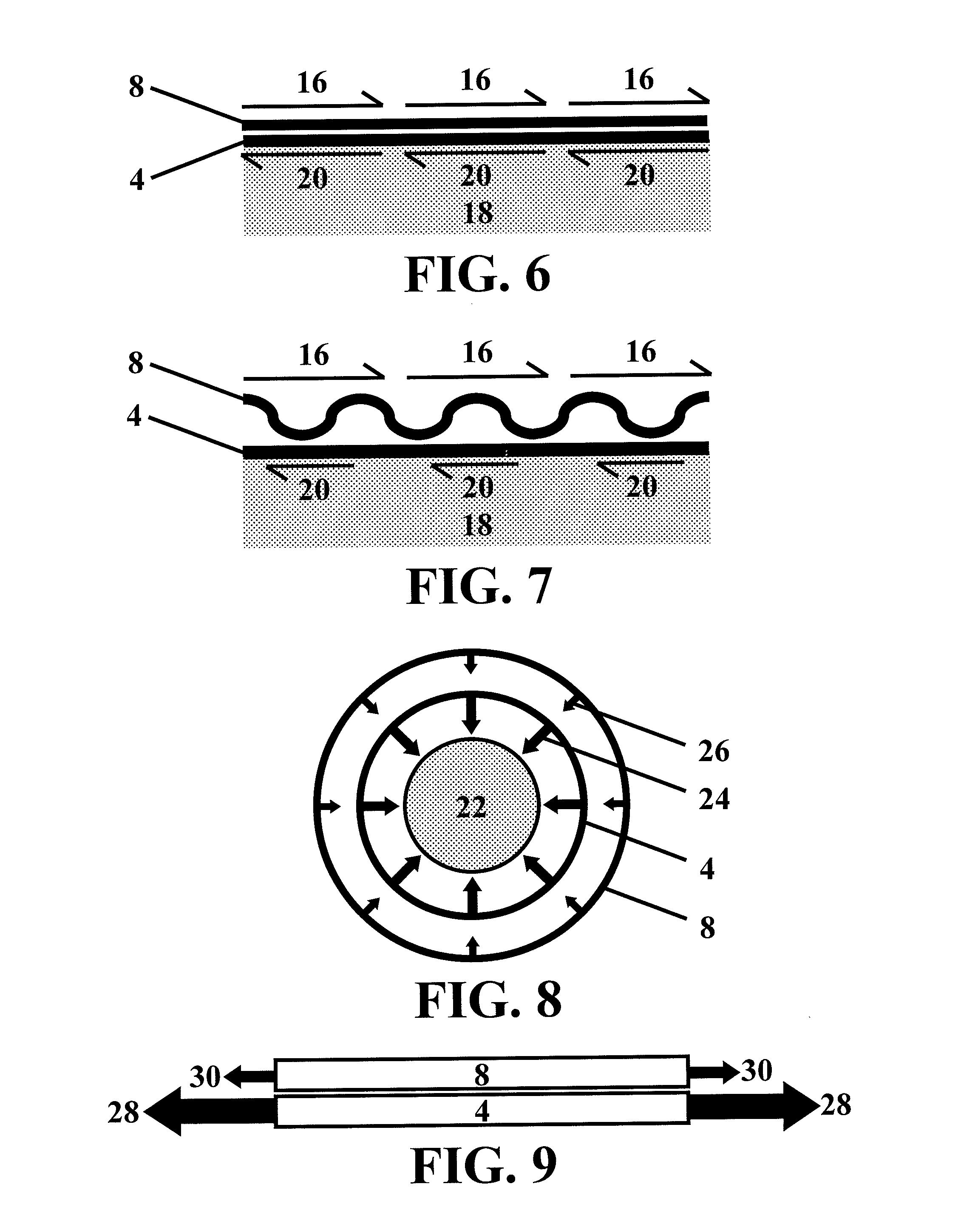
[0043] The relationship between the tautness of the fabric layers and the tensile loads and compression present in an abrasion resistant fabric 2 in the fitted state will now be discussed. The tautness of the fabric layers may be related to the tensile load corresponding to the restoring force acting in the plane of the fabric layers, as depicted in FIG. 9. The tensile load may correspond to a hoop force substantially oriented in the circumferential direction of the covered body part. The compression provided by the fabric layers may correspond to the force directed inwards against the covered body part, as depicted in FIG. 8, and may be substantially oriented perpendicular to the fabric layers. Without wishing to be bound by theory, an increase in the tautness of a fabric layer, and the corresponding increase in tensile load, may result in an increase in the compression provided by the fabric layers to an underlying covered body part.
[0044] The preferential abrasion resistance of the inventive fabric is presented in more detail in FIGS. 2 and 5-7. A shear force 14 may be applied to fabric 2 in both an x and/or y direction, as shown in FIG. 2. A shear force 16 may be applied to outer fabric layer 8 of abrasion resistant fabric 2 while disposed on the skin 18 of an individual, as detailed in FIGS. 5-7. The shear force transmitted to skin 18 is represented by shear force 20. Without wishing to be bound by theory, the friction between the fabric layers, and the ability of at least one of the fabric layers to slide relative to the other, may affect the shear stress 20 transmitted to underlying skin 18. As detailed above, the fabric layers may be oriented in a predetermined enhanced sliding relationship to reduce the friction between the layers and the shear stress transmitted to the underlying skin. However, the relative tautness of, and compression provided by, each fabric layer may also affect both the friction between the layers and the ability of one or both of the fabric layers to slide. For instance, when inner and outer fabric layers 4 and 8 are both loose, as depicted in FIG. 5, bunching and misalignment of the abrasion resistant fabric may occur limiting the slidability of one or both layers. Consequently, skin 18 may experience a relatively high shear force 20. When both inner and outer fabric layers 4 and 8 are taut, as depicted in FIG. 6, the increased compressive force from outer layer 8 may result in increased friction between is the two fabric layers. Thus, skin 18 may again experience a relatively high shear force 20. When inner fabric layer 4 is relatively more taut than outer fabric layer 8, as depicted in FIG. 7, and fabric layer 8 is not so taut as to excessively increase the friction between the layers, outer fabric layer 8 may slide along inner fabric layer 4, thus, reducing the shear force 20 transmitted to skin 18.
[0045] In view of the above, the inner fabric layer may be configured to bear a greater tensile load and/or provide a greater amount of compression as compared to the outer fabric layer when the abrasion resistant fabric 2 is in a fitted state. An exemplary representation of the relative compression applied by the first fabric layer 4 and second fabric layers 8 to a limb 22, or other body part, in the fitted state, is presented in FIG. 8. The greater compression provided by the inner fabric layer 4 is indicated by the larger arrows 24. The lesser compression provided by the outer fabric layer 8 is indicated by the smaller arrows 26. FIG. 9 presents an exemplary representation of the different tautness of each fabric layer as represented by different tensile loading. Inner fabric layer 4 is subject to a greater tensile load 28 in the fitted stated than is outer fabric layer 8.
[0046] Providing a tighter fitting inner fabric layer 4 may help to reduce the friction between opposing layers. Without wishing to be bound by theory, it is believed that a taut inner fabric layer 4 may provide a smooth regular surface for the outer layer to slide upon and also help to avoid misalignment and bunching of the inner and outer layers during loading such as might be experienced during a crash. Misalignment of the layers and/or bunching of the material may lead to either increased friction between the layers and/or less desirable sliding of the outer layer relative to the inner layer. Alternatively, if the compression from, or the tautness of, the outer fabric layer 8 is too great, the amount of friction between the fabric layers may increase due to the increased normal force. Therefore, the relative compression provided by, and the tautness of, each fabric layer for a desired fit of a garment, may be selected to avoid misalignment and bunching of the layers as well as excessive friction at the interface between the fabric layers.
[0047] One way to characterize a fabric layer is by its stretch and/or recovery. A stretch property of a fabric is a measure of how much a fabric can stretch in its length and/or width dimensions, and is usually expressed in terms of a percentage. A recovery property of a fabric, sometimes referred to as modulus, defines the degree to which a material exerts a restoring force to pull itself back to its original size and shape. Recovery is usually expressed in terms of a percentage. Recovery may also be expressed in terms of a mass needed to stretch a fabric a certain percentage (this may be measured in grams). For example, a sweater may be stretched by deformation of the knit structure. This is known as "mechanical stretch". However, because the knit structure is relatively loose, the sweater does not exert a particularly large restoring force. By comparison, SPANDEX has both "mechanical stretch" and "material stretch". Namely, the base material that each thread is made of is able to stretch. This imparts a larger restoring force in a sweater including SPANDEX as compared to a sweater without elastic fibers. This difference in the restoring force may be characterized as a difference in the recovery of each fabric. For instance a fabric with a recovery of 80% will experience a larger restoring force than a fabric with a recovery of 30%. Similarly, a fabric with a recovery property of 1000 grams will experience a larger restoring force than a fabric with a recovery property of 100 grams. So, two geometrically identical tube-like garments would provide different amounts of compression when made from fabrics with different amounts of recovery. Similarly, the difference in tensile loads present in two geometrically identical fabrics, when strained by the same amount, may be proportional to the difference in the recovery property of the two fabrics. However, when two fabrics are not geometrically identical, the fabrics may have different strains when deformed. The difference in strains may result in different tensile loads in the two fabrics even when the two fabrics have substantially the same recovery property. Consequently, the difference in tensile loads present in different fabrics may be a function of both the difference in recovery properties and differences in the areas and/or strain of the fabrics when in a fitted state.
[0048] In view of the above, the compression provided by, and the tautness of each layer may be expressed using the recovery percentage of a fabric layer. In one embodiment, the first inner fabric layer 4 has a first recovery property greater than a second recovery property of the second outer fabric layer 8. In some embodiments, the first recovery property may be at least 5%, 10%, 15%, or 20% greater than the second recovery property. In certain embodiments, the first recovery property may be greater than any of the forgoing percentages and less than 230% greater than the second recovery property. In another embodiment, the first inner fabric layer 4 has a greater tensile load than the second outer fabric layer 8. In some embodiments, the tensile load of the first inner fabric layer 4 may be at least 5%, 10%, 15%, or 20% greater than the tensile load of the second outer fabric layer 8. In certain embodiments, the tensile load of the first fabric layer 4 may be greater than any of the forgoing percentages and less than 230% greater than the tensile load of the second outer fabric layer 8. In yet another embodiment, the compression provided by, and the tautness of, each layer may be provided, at least in part, by a difference in size of the fabric layers. In such an embodiment the fabric layers are stretched by different amounts (i.e. different strains) when in the fitted state. It is this difference in the amount of deformation of each layer that provides the difference in compression and tautness of each fabric layer. In one embodiment, a first area of the first fabric layer 4 is greater than a second area of the second fabric layer 8 by 5% to 15%. Alternatively, the first area may be 5%-30% greater than the second area. Therefore, the difference in compression provided by, and tautness of, each fabric layer may be due to a difference in an intrinsic recovery property of each fabric layer and/or the sizing of each fabric layer.
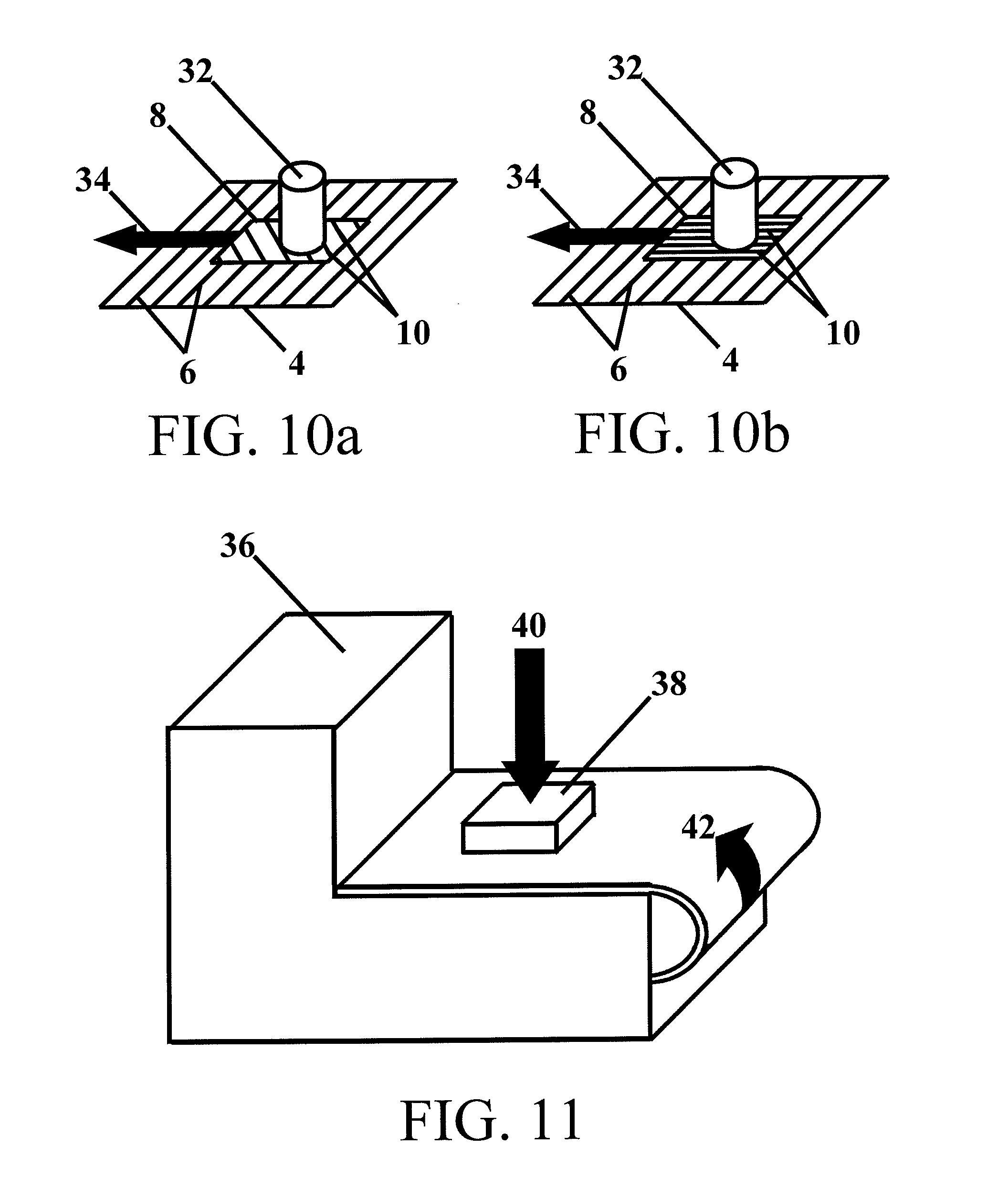
[0049] Dynamic friction tests were performed for various fabric layer combinations and fabric direction orientations, see FIGS. 10a and 10b. During testing, inner fabric layer 4 was the bottom layer and outer fabric layer 8 was the upper layer. The bottom layer was strained to 10% and held prior to, and during, testing to provide a taut inner surface as would be present when incorporated into a garment and in the fitted state. A known mass 32 was applied to the top of outer fabric layer 8. A force 34 was then applied in the horizontal direction. Once mass 32 obtained a steady state velocity, force 34 was recorded to determine a dynamic coefficient of friction between the two layers. Testing was conducted for multiple orientations of the first direction 6 and second direction 10 as depicted in FIGS. 10a and 10b. Fabrics were tested from multiple manufacturers, including MITI Spa and Christian Eschler AG. Fabrics tested from MITI Spa included Action, Ariane, Asteria, Asteria Pro, Coach Interpower, Gavia, Lombardia, to Matrix, Shield, Superdry, Tahiti, Thermoair, Thermoroubaix, Topazio, Wave, and Zaffiro. Fabrics tested from Christian Eschler AG include product numbers 11497, 63182, 63285, 63835, 63872, 63934, 63942, and 63944. A summary of selected test results is presented in Table 1.
TABLE-US-00001 TABLE 1 Dynamic Friction Testing Inner Outer Fabric Layer Fabric Layer Orientation .mu. Dry .mu. Wet 63934 Matrix 0 0.88 .+-. 0.10 1.01 .+-. 0.12 63934 Matrix +45 0.62 .+-. 0.06 0.71 .+-. 0.08 63934 Matrix -45 0.63 .+-. 0.06 0.70 .+-. 0.08 63934 Matrix +90 0.38 .+-. 0.03 0.44 .+-. 0.05 63934 Matrix -90 0.42 .+-. 0.03 0.48 .+-. 0.05 63934 63835 0 0.81 .+-. 0.10 0.94 .+-. 0.12 63934 63835 +30 0.65 .+-. 0.09 0.77 .+-. 0.11 63934 63835 -30 0.71 .+-. 0.09 0.83 .+-. 0.11 63934 63835 +45 0.58 .+-. 0.07 0.68 .+-. 0.08 63934 63835 -45 0.58 .+-. 0.07 0.68 .+-. 0.08 63934 63835 +60 0.43 .+-. 0.05 0.50 .+-. 0.06 63934 63835 -60 0.50 .+-. 0.05 0.59 .+-. 0.06 63934 63835 +90 0.34 .+-. 0.03 0.40 .+-. 0.04 63934 63835 -90 0.36 .+-. 0.03 0.42 .+-. 0.04
[0050] As detailed above in Table 1, the coefficient of friction decreases as the orientation is varied from 0.degree. to 90.degree., with the 90.degree. orientation having the lowest coefficient of friction for the tested fabric systems. The tested fabrics had a range of coefficients of friction in a .+-.90.degree. orientation ranging from approximately 0.3 to 0.4 in the dry state and 0.4 to 0.5 in the wet state. However, it is possible that coefficients of friction between the layers may be as low as 0.15 or less when these fabric layers are combined with low surface energy coatings, such as a super hydrophobic coating, or when the layers are made from finer fabrics.
[0051] Abrasion testing was conducted for selected fabric combinations from the dynamic friction testing. Videos of bicycle crashes were analyzed to determine an approximate coefficient of friction between a rider and the ground. Without wishing to be bound by theory, an average coefficient of friction between a rider and a dry smooth pavement may be calculated for a bicycle crash by assuming: a constant normal force equal to the estimated weight of a rider, bicycle, and equipment; estimating the distance of a crash; and calculating the initial kinetic energy of a rider. The calculated coefficient of friction from multiple examined crashes was approximately 0.6-0.7 on dry smooth pavement. To simulate the crash a high speed belt sander 36 was fitted with a belt having a coefficient of friction between 0.6-0.7 (600 grit). A flesh analog 38 was then wrapped in the abrasion resistant fabric 2 with an approximate relative orientation of 90.degree. between the two fabric layers. The abrasion resistant fabric 2 was stretched as it would be in the fitted state. Flesh analog 38 may be any number of materials ranging from chicken breasts, to whole pig carcasses, to ballistics gel. The average skin area in contact with the riding surface during a crash was estimated to determine an average normal pressure applied to the skin during a bicycle crash. The average normal pressure was estimated to be 13.8 kPa (2 psi). Normal force 40 may be selected to provide the calculated average normal pressure 13.8 kPa (2 psi) to flesh analog 38 during testing. After flesh analog 38 is positioned and normal force 40 is applied, the belt sander 36 may be activated to turn the belt in a direction 42. The average speed for crashes during competitive events is approximately 27.5 MPH. The speed and duration of testing may be selected to dissipate a similar amount of energy per unit area as experienced during an actual bicycle crash. The duration of testing may include an appropriate factor of safety to take into account the multiple assumptions regarding average contact pressures, coefficients of friction, and/or differences between an actual crash speed and the testing speed. The present abrasion testing was conducted at 21.6 MPH for six seconds to simulate the energy dispation of a two second crash at 27.5 MPH with a conservative factor of safety. After testing, the abraded surfaces were evaluated and the performance of each fabric combination was evaluated. Results from the abrasion testing are presented below in Table 2.
TABLE-US-00002 TABLE 2 Abrasion Testing Inner Fabric Outer Fabric Layer Layer .mu. (+90.degree.) Result 63934 Matrix 0.38 .+-. 0.03 Mild 63934 63835 0.34 .+-. 0.03 Moderate 63934 Asteria -- Moderate 63934 Asteria Pro -- Severe 63934 63182 -- Moderate Zaffiro Matrix -- Mild Zaffiro 63835 -- Moderate Zaffiro Asteria -- Moderate Zaffiro Asteria Pro -- Severe Zaffiro Shield -- Mild Zaffiro 63182 -- Moderate
[0052] As presented above in Table 2, several fabric combinations that yielded low friction coefficients in the earlier tests were tested for their abrasion characteristics. Without wishing to be bound by theory, and as illustrated from the first two results presented in Table 2, and the related coefficients of friction, the interlayer frictional properties and abrasion properties appear to be independent. The fabric system comprising 63934, as the inner fabric layer, and 63835, as the outer fabric layer, yielded the lowest friction coefficients wet or dry. However, 63835 had a waffled pyramidal texture. Without wishing to be bound by theory, 63835, when used as an outer fabric layer tended to grab the abrasive belt, stretch, and then tear, exposing the inner layer. The fabric system comprising 63934, as the inner fabric layer, and Matrix, as the outer fabric layer, had a slightly higher coefficient of friction, but performed better in abrasion tests. The Matrix fabric was flatter and more planar in structure than 63835. Without wishing to be bound by theory, the lack of pyramidal or other protruding structures on the Matrix fabric produced less friction with the abrasive belt. For practical purposes, all of the fabric systems discussed in Table 2 could be used in sports apparel. However, the more abrasion-resistant combinations may be more desirable for the highest risk locations such as the elbow, shoulder, knee and buttocks. In one embodiment, less abrasion-resistant combinations could be placed in lower risk areas such as the back and lower leg, and could be optimized for other parameters such as muscle compression, aerodynamics, heat stress, and/or visual aesthetics.
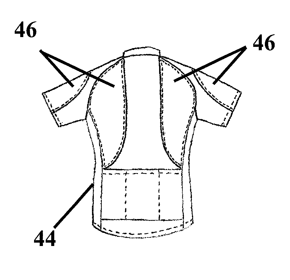
[0053] Sports garments 44 may incorporate abrasion resistant fabric 46 at localized high risk areas as depicted in FIGS. 12-15. High risk areas may include, but are not limited to, the upper back, lower back, shoulders, upper and lower arms, knees, buttocks, outer hips, and outer thighs. Alternatively, the garment may be made entirely from the abrasion resistant fabric 46. Two embodiments of a tube like garment 48, as might be used for a sleeve, are presented in FIGS. 16-18. Tube like garment 48 may include inner fabric layer 4 and outer fabric layer 8 arranged and oriented as detailed above. Outer fabric layer 8 may completely envelope inner layer 4 and include a single seam 50 as shown in FIG. 17. Alternatively, layers 4 and 8 may be formed as two seamless tubes and/or may be seamlessly joined together. In another embodiment, outer fabric layer 8 may only be positioned on a portion of inner layer 4 and include two or more seams 50 as shown in FIG. 18.
[0054] In some embodiments, one or more pads may be incorporated into a garment 44, such as the bicycle bib depicted in FIG. 19 or other possible protective articles. The pad(s) may provide additional impact protection in areas such as the outer hips, knees, elbows, or other appropriate location. A pocket 52 for selective insertion or removal of a pad 54 may be provided on either of inner fabric layer 4 or outer fabric layer 8, or between the two fabric layers. The pocket 52 may be formed of the inner and outer fabric layers, or include another fabric. Where a separate pouch is provided between the inner and outer fabric layers, the pouch may be arranged and oriented in a predetermined enhanced sliding relationship to the first inner fabric layer and/or second outer fabric layer. Pocket 52 may include fasteners 56 to hold the pocket closed during use. Fasteners 56 may include, but are not limited to, buttons, snaps, zippers, and/or hook and loop fasteners. In some embodiments, pad 54 may be partially or entirely covered by a third fabric layer having a third direction. The fabric layers may be arranged with a predetermined orientation of the third direction and either or both of the first direction and the second direction to provide enhanced sliding of the third fabric layer containing pad. The third fabric layer may be formed of the same fabric as the first fabric layer or the second fabric layer, or from another fabric arrangement. In some embodiments the third fabric layer may have a smooth planar surface. The third fabric layer may be joined, such as by adhesive, to the pad. Pad 54 may be made from a variety of materials including, but not limited to, plastic, metal, and/or reactive padding materials. In one embodiment pad 54 may be made from d3o reactive padding by d3o lab.
[0055] While the present teachings have been described in conjunction with various embodiments and examples, it is not intended that the present teachings be limited to such embodiments or examples. On the contrary, the present teachings encompass various alternatives, modifications, and equivalents, as will be appreciated by those of skill in the art.
[0056] Accordingly, the foregoing description and drawings are by way of example only.
* * * * *
D00000
D00001
D00002
D00003
D00004
D00005
D00006
D00007
XML
uspto.report is an independent third-party trademark research tool that is not affiliated, endorsed, or sponsored by the United States Patent and Trademark Office (USPTO) or any other governmental organization. The information provided by uspto.report is based on publicly available data at the time of writing and is intended for informational purposes only.
While we strive to provide accurate and up-to-date information, we do not guarantee the accuracy, completeness, reliability, or suitability of the information displayed on this site. The use of this site is at your own risk. Any reliance you place on such information is therefore strictly at your own risk.
All official trademark data, including owner information, should be verified by visiting the official USPTO website at www.uspto.gov. This site is not intended to replace professional legal advice and should not be used as a substitute for consulting with a legal professional who is knowledgeable about trademark law.