Abdominal Squat Machine
Jones; Anthony ; et al.
U.S. patent application number 13/171009 was filed with the patent office on 2011-12-29 for abdominal squat machine. This patent application is currently assigned to Anthony Jones. Invention is credited to Anthony Jones, David Rawlings.
| Application Number | 20110319237 13/171009 |
| Document ID | / |
| Family ID | 45353079 |
| Filed Date | 2011-12-29 |


View All Diagrams
| United States Patent Application | 20110319237 |
| Kind Code | A1 |
| Jones; Anthony ; et al. | December 29, 2011 |
ABDOMINAL SQUAT MACHINE
Abstract
An apparatus for performing abdominal and squat exercises is provided with a frame having a support member, a first end and a second end that operate to provide horizontal stabilization, and at least two leg securing bars extending substantially transversely from the frame of the apparatus. A first leg securing bar may be disposed at a first location along the frame, and a second leg securing bar may be disposed at a second location along the frame such that the arrangement of the leg securing bars in the first and second locations permits the apparatus to operate as an exercise device for abdominal and squat exercises. A user of the apparatus may position one or more legs in between the leg securing bars and perform abdominal and squat exercises without having to readjust the leg securing bars and without having to move one or more feet thereof in between routines.
| Inventors: | Jones; Anthony; (Greenlawn, NY) ; Rawlings; David; (Sound Beach, NY) |
| Assignee: | Jones; Anthony Greenlawn NY |
| Family ID: | 45353079 |
| Appl. No.: | 13/171009 |
| Filed: | June 28, 2011 |
Related U.S. Patent Documents
| Application Number | Filing Date | Patent Number | ||
|---|---|---|---|---|
| 61398648 | Jun 29, 2010 | |||
| Current U.S. Class: | 482/140 |
| Current CPC Class: | A63B 21/00047 20130101; A63B 23/0211 20130101; A63B 2023/0411 20130101 |
| Class at Publication: | 482/140 |
| International Class: | A63B 23/02 20060101 A63B023/02 |
Claims
1. An apparatus for performing abdominal and squat exercises, the apparatus comprising: a frame having a support member, a first end and a second end, the support member extending between the first and second ends a predetermined length, the first and second ends being sized and shaped such that the first and second ends operate to provide horizontal stabilization to the frame; and at least two leg securing bars extending substantially transversely from the frame, a first leg securing bar of the at least two leg securing bars being disposed at a first predetermined location along the frame and a second leg securing bar of the at least two leg securing bars being disposed at a second predetermined location along the frame such that the arrangement of the at least two leg securing bars in the first and second predetermined locations permits the apparatus to operate as an exercise device for both one or more abdominal exercises and one or more squat exercises.
2. The apparatus of claim 1, wherein the at least two leg securing bars operate to: (i) permit a user of the apparatus to position one or more legs of the user in between the at least two leg securing bars and to perform the one or more abdominal exercises and the one or more squat exercises without having to readjust or modify the position of the at least two leg securing bars; and (ii) retain one or more feet of the user in substantially the same position when the user is performing the one or more abdominal exercises and the one or more squat exercises.
3. The apparatus of claim 2, wherein at least one of: (i) the first leg securing bar operates to support one or more calf muscles and/or one or more knees of the user, and the second leg securing bar operates to support the one or more feet, one or more shins and/or one or more ankles of the user; (ii) the first leg securing bar and second leg securing bar operate to retain the one or more feet of the user at least one of: substantially flat on the floor, substantially on the floor, substantially on the floor and partially on a portion of the first end, and substantially on the floor and partially on a portion of the second end; (iii) the first and second leg securing bars operate to prevent movement of the one or more legs of the user during operation, focusing the exercise resistance on the targeted muscles; and (iv) the frame operates to direct resistance to the abdominal muscles and leg muscles of the user by focusing the body mass of the user into a training resistance routine.
4. The apparatus of claim 3, wherein the first and second ends each have a substantially transverse member extending laterally therefrom and being sized and shaped such that the respective transverse members of the first and second ends operate to provide further horizontal stabilization to the frame.
5. The apparatus of claim 3, wherein the frame is tubular such that the support member and the first and second ends include top, bottom and side surfaces and at least one of the first and second ends is angled outwardly in relation to the support member.
6. The apparatus of claim 5, wherein the first leg securing bar: (i) is disposed on the support member proximately to where the second end is joined to the support member; (ii) extends outwardly from each side surface of the support member in opposite directions; and (iii) includes opposite free ends and has mounted on the opposite free ends thereof a pair of foam or vinyl pads each having a central bore that operates to receive the first leg securing bar therein.
7. The apparatus of claim 6, wherein the second leg securing bar: (i) is disposed on a lower portion of the second end; (ii) extends outwardly from each side of the second end in opposite directions; and (iii) includes opposite free ends and has mounted on the opposite free ends thereof a pair of foam or vinyl pads each having a central bore that operates to receive the second leg securing bar therein.
8. The apparatus of claim 7, wherein at least one of: (i) the first leg securing bar is permanently affixed to the support member in the predetermined first location; and (ii) the second leg securing bar operates to be freely slideably engaged with the second end of the frame when no lateral force or pressure is applied thereto and operates to be retained in the predetermined second location when a lateral force or pressure is applied by the one or more legs of the user.
9. The apparatus of claim 7, wherein: (i) the second end includes a telescoping member extending substantially collinearly therefrom, the telescoping member having a member extending substantially transverse therefrom such that the telescoping member and the substantially transverse member are substantially L-shaped or substantially T-shaped; and (ii) the telescoping member is sized and shaped to fit into the tubular second end and the tubular second end operates to telescope over the telescoping member as the telescoping member slides into the tubular second end, thereby decreasing a height of the frame, and out of the tubular second end, thereby increasing the height of the frame.
10. The apparatus of claim 9, wherein the height of the frame is adjustable to dispose a center of gravity of the user of the apparatus inwardly of the first end such that the second end of the apparatus will remain on the floor during the exercise routine(s) of the user.
11. The apparatus of claim 9, wherein: (i) the height of the frame and/or a height of the apparatus is at least: about 15 inches; 15 inches-about 175/8 inches; about 175/8 inches; and (ii) a length of the frame and/or a length of the apparatus is at least: about 287/8 inches; about 287/8 inches-about 401/4 inches; about 401/4 inches.
12. The apparatus of claim 9, wherein the telescoping member and the tubular second end operate to be releasably coupled together and/or disengaged with an engaging pin being disposed in and/or removed from at least one hole of the telescoping member and at least one hole of the second end when the at least one holes are aligned and the pin extends into and/or is removed from an internal bore of the second end of the tubular frame and an internal bore of the telescoping member.
13. The apparatus of claim 9, further comprising a handle locking mechanism disposed on the telescoping second end, the handle locking mechanism having a handle pivotally attached to a pair of mounting posts extending substantially perpendicularly from the telescoping second end and to a pin extending between the mounting posts, the pin operating to couple the handle to the mounting posts and to a spring that operates to bias a first end of the handle away from, and a second end of the handle towards, the telescoping second end such that a locking pin disposed on, and extending substantially perpendicularly from, the second end of the handle is similarly biased towards the telescoping second end of the frame and operates to selectively engage one of a plurality of spaced apart holes collinearly positioned along a surface of the telescoping member and an engagement hole of the telescoping second end of the frame, wherein the handle locking mechanism operates to couple the telescoping second end of the frame with the telescoping member, thereby limiting extension and/or retraction of the telescoping member when the locking pin is engaged with the one of the plurality of holes and the engagement hole of the telescoping second end of the frame, and to decouple the telescoping member and the telescoping second end of the frame when a downward pressure is applied to the first end of the handle to overcome the force of the spring and to remove the locking pin from the engagement hole of the telescoping second end of the frame and the one of the plurality of holes of the telescoping member.
14. The apparatus of claim 9, wherein the first leg securing bar operates to be slideably adjustable along a track portion of the support member and the second leg securing bar operates to be slideably adjustable along a second track portion of the telescoping member, the track portion of the support member being formed along the length of the support member and having at least one hole in the support member and the second track portion of the telescoping member being formed along the length of the telescoping member and having at least one hole in the telescoping member.
15. The apparatus of claim 14, wherein: (i) the first and second leg securing bars are each affixed to respective adjustment brackets each having a space therethrough and a central bore therein, the adjustment bracket of the first leg securing bar operating to receive the support member therein and to be slideably engaged with the track portion of the support member, the adjustment bracket of the second leg securing bar operating to receive the telescoping member therein and to be slideably engaged with the second track portion of the telescoping member; (ii) the first leg securing bar and the track portion of the support member operate to be releasably coupled together and/or disengaged with an engaging pin being disposed in and/or removed from the at least one hole of the track portion and the central bore of the adjustment bracket of the first leg securing bar such that the pin extends into and/or is removed from an internal bore of the support member of the tubular frame; and (iii) the second leg securing bar and the second track portion of the telescoping member operate to be releasably coupled together and/or disengaged with another engaging pin being disposed in and/or removed from the at least one hole of the second track portion and the central bore of the adjustment bracket of the second leg securing bar such that the pin extends into and/or is removed from an internal bore of the telescoping member.
16. The apparatus of claim 14, further comprising a seat disposed on the support member such that the seat operates to support the user of the apparatus.
17. The apparatus of claim 16, wherein the seat is affixed to an adjustment bracket having a space therethrough for receiving the support member and being slideably engaged with the track portion of the support member, the adjustment bracket having a central bore therein, wherein the seat and the track portion operate to be releasably coupled together and/or disengaged from each other with an engaging pin being disposed in and/or removed from the at least one hole of the track portion and the central bore of the adjustment bracket such that the pin extends into and/or is removed from an internal bore of the support member of the tubular frame.
18. The apparatus of claim 5, wherein the first end of the frame is shorter in length than the second end of the frame and the first and second ends of the frame are angulated such that the support member is oriented in a slightly declined manner in a direction from the second end of the frame to the first end of the frame.
19. The apparatus of claim 5, further comprising a seat disposed on the support member such that the seat operates to support the user of the apparatus.
20. The apparatus of claim 19, wherein the seat is affixed to an adjustment bracket having a space therethrough for receiving the support member and being slideably engaged with a track portion of the support member, the track portion of the support member being formed along the length of the support member and having at least one hole in the support member, the adjustment bracket having a central bore therein, wherein the seat and the track portion operate to be releasably coupled together and/or disengaged from each other with an engaging pin being disposed in and/or removed from the at least one hole of the track portion and the central bore of the adjustment bracket such that the pin extends into and/or is removed from an internal bore of the support member of the tubular frame.
Description
CROSS-REFERENCE TO RELATED APPLICATIONS
[0001] This application claims the benefit of U.S. Provisional Patent Application No. 61/398,648, filed Jun. 29, 2010, the entirety of which is incorporated herein by reference.
FIELD OF THE INVENTION
[0002] The present invention relates to exercise machines, in particular, exercise machines providing combined abdominal and squat routines.
BACKGROUND OF THE INVENTION
[0003] Abdominal and squat exercises are an essential part of a proper strengthening routine. Abdominal exercises such as crunches and sit-ups provide resistance to the abdominal muscles including the rectus abdominus and external obliques. Sit-ups and crunches are commonly performed on the ground as the torso is pulled from a supine position to a semi-inclined position by contracting the abdominal muscles. Alternately, some machines have been developed to assist with sit-ups and crunches that similarly provide resistance to the abdominal muscles during contraction. Additionally, passive apparatus such as an inclined bench may further concentrate abdominal resistance to a specific region and limit inadvertent secondary assist muscle use.
[0004] Squat exercises provide resistance primarily to the quadriceps, hamstrings, gluteals, hip flexors and calf muscles. Most commonly, squat exercises are performed utilizing a straight barbell with free-weights added equally to opposing ends of the barbell. The barbell is placed relatively behind the neck on the trapezius muscle. The bar is loaded on the trapezius muscle while in the standing position, with ones knees slightly bent, and a downward moving phase begins in which the body is slowly lowered to the floor by bending at the hips and knees. Once the upper legs are almost parallel to the floor, the upward phase begins by exerting force on the ground with the legs, straightening them to return to the standing position.
[0005] The conventional abdominal and squat exercises are performed separately, adding additional time to the workout. Furthermore, the conventional abdominal and squat exercises each have limited success due to inadvertent errors and/or positioning. Proper form is essential to both types of exercises and a lack thereof can even lead to serious injury. Squat exercises often require a spotter (second person assisting and monitoring the primary exerciser) to provide assistance in the event that the exerciser fails. As a result, this type of exercise is seldom performed by a single exerciser. The squat also requires frequently adding and removing weights between sets. Frequent injuries to the knees are common due to the tremendous amount of strain focused in the knee area from the barbell and weights. Squat assist machines such as the Smith Press and abdominal assist machines are large and costly and therefore are usually only found in commercial gymnasiums. As a result, it is necessary to travel and pay for membership at fitness centers to gain the ability to perform these routines.
[0006] Thus, it would therefore be desirable to provide an apparatus that operates to permit a user of the apparatus to perform squat and abdominal exercise routines with seamless transition between squat and abdominal routines without having to adjust/modify the apparatus when switching between such routines. The present invention provides a novel apparatus for simultaneously performing both abdominal and squat exercises that overcomes the inherent disadvantages associated with the conventional designs and methods.
SUMMARY OF THE INVENTION
[0007] In accordance with one or more embodiments of the present invention, an apparatus for performing abdominal and squat exercises is provided with a frame having a support member, a first end and a second end that operate to provide horizontal stabilization, and at least two leg securing bars extending substantially transversely from the frame of the apparatus. A first leg securing bar may be disposed at a first location along the frame, and a second leg securing bar may be disposed at a second location along the frame such that the arrangement of the leg securing bars in the first and second locations permits the apparatus to operate as an exercise device for abdominal and squat exercises. A user of the apparatus may position one or more legs in between the leg securing bars and perform abdominal and squat exercises without having to readjust the leg securing bars and without having to move one or more feet thereof in between routines. The present invention of the instant application allows for cost reduction associated with employing, buying, maintaining, etc. exercise machines because both abdominal and squat exercise routines may be performed thereon without having to adjust/modify any settings (e.g., the position of first leg securing bar, the position of second leg securing bar, the position of a seat, etc.) when transitioning between such routines, and provides for efficient use of space (e.g., because only one machine is needed to perform abdominal and squat exercises rather than two machines).
[0008] In accordance with one or more embodiments of the present invention, an apparatus for performing abdominal and squat exercises, the apparatus includes: a frame having a support member, a first end and a second end, the support member extending between the first and second ends a predetermined length, the first and second ends being sized and shaped such that the first and second ends operate to provide horizontal stabilization to the frame; and at least two leg securing bars extending substantially transversely from the frame, a first leg securing bar of the at least two leg securing bars being disposed at a first predetermined location along the frame and a second leg securing bar of the at least two leg securing bars being disposed at a second predetermined location along the frame such that the arrangement of the at least two leg securing bars in the first and second predetermined locations permits the apparatus to operate as an exercise device for both one or more abdominal exercises and one or more squat exercises.
[0009] The at least two leg securing bars may operate to: (i) permit a user of the apparatus to position one or more legs of the user in between the at least two leg securing bars and to perform the one or more abdominal exercises and the one or more squat exercises without having to readjust or modify the position of the at least two leg securing bars; and (ii) retain one or more feet of the user in substantially the same position when the user is performing the one or more abdominal exercises and the one or more squat exercises. The first leg securing bar may operate to support one or more calf muscles and/or one or more knees of the user, and the second leg securing bar may operate to support one or more feet, one or more shins and/or one or more ankles of the user. The first leg securing bar and second leg securing bar may operate to retain one or more feet of the user at least one of: substantially flat on the floor, substantially on the floor, substantially on the floor and partially on a portion of the first end, and substantially on the floor and partially on a portion of the second end. The first and second leg securing bars may operate to prevent movement of the one or more legs of the user during operation, focusing the exercise resistance on the targeted muscles. The first leg securing bar: (i) may be disposed on the support member proximately to where the second end is joined to the support member; (ii) may extend outwardly from each side surface of the support member in opposite directions; and (iii) may have mounted on opposite free ends thereof a pair of foam or vinyl pads each having a central bore that operates to receive the first leg securing bar therein. The second leg securing bar: (i) may be disposed on a lower portion of the second end; (ii) may extend outwardly from each side of the second end in opposite directions; and (iii) may have mounted on opposite free ends thereof a pair of foam or vinyl pads each having a central bore that operates to receive the second leg securing bar therein. The first leg securing bar may be permanently affixed to the support member in the predetermined first location. The second leg securing bar may operate to be freely slideably engaged with the second end of the frame when no lateral force or pressure is applied thereto and may operate to be retained in the predetermined second location when a lateral force or pressure is applied by the one or more legs of the user. The first leg securing bar may operate to be slideably adjustable along a track portion of the support member and the second leg securing bar may operate to be slideably adjustable along a second track portion of the telescoping member, the track portion of the support member being formed along the length of the support member and having at least one hole in the support member and the second track portion of the telescoping member being formed along the length of the telescoping member and having at least one hole in the telescoping member.
[0010] The first and second leg securing bars may be each affixed to respective adjustment brackets each having a space therethrough and a central bore therein, the adjustment bracket of the first leg securing bar operating to receive the support member therein and to be slideably engaged with the track portion of the support member, the adjustment bracket of the second leg securing bar operating to receive the telescoping member therein and to be slideably engaged with the second track portion of the telescoping member. The first leg securing bar and the track portion of the support member may operate to be releasably coupled together and/or disengaged with an engaging pin being disposed in and/or removed from the at least one hole of the track portion and the central bore of the adjustment bracket of the first leg securing bar such that the pin extends into and/or is removed from an internal bore of the support member of the tubular frame. The second leg securing bar and the second track portion of the telescoping member may operate to be releasably coupled together and/or disengaged with another engaging pin being disposed in and/or removed from the at least one hole of the second track portion and the central bore of the adjustment bracket of the second leg securing bar such that the pin extends into and/or is removed from an internal bore of the telescoping member.
[0011] The frame may operate to direct resistance to the abdominal muscles and leg muscles of the user by focusing the body mass of the user into a training resistance routine. The first and second ends of the frame may each have a substantially transverse member extending laterally therefrom and being sized and shaped such that the respective transverse members of the first and second ends operate to provide further horizontal stabilization to the frame. The frame may be tubular such that the support member and the first and second ends include top, bottom and side surfaces. At least one of the first and second ends may be angled outwardly in relation to the support member. The second end may include a telescoping member extending substantially collinearly therefrom, and the telescoping member may have a member extending substantially transverse therefrom such that the telescoping member and the substantially transverse member are substantially L-shaped or substantially T-shaped. The telescoping member may be sized and shaped to fit into the tubular second end, and the tubular second end may operate to telescope over the telescoping member as the telescoping member slides into the tubular second end, thereby decreasing a height of the frame, and out of the tubular second end, thereby increasing the height of the frame. The telescoping member and the tubular second end may operate to be releasably coupled together and/or disengaged with an engaging pin being disposed in and/or removed from at least one hole of the telescoping member and at least one hole of the second end when the at least one holes are aligned and the pin extends into and/or is removed from an internal bore of the second end of the tubular frame and an internal bore of the telescoping member. The first end of the frame may be shorter in length than the second end of the frame, and the first and second ends of the frame may be angulated such that the support member is oriented in a slightly declined manner in a direction from the second end of the frame to the first end of the frame.
[0012] The height of the frame may be adjustable to dispose a center of gravity of the user of the apparatus inwardly of the first end such that the second end of the apparatus will remain on the floor during the exercise routine(s) of the user. The height of the frame and/or a height of the apparatus may be at least: about 15 inches; 15 inches-about 175/8 inches; about 175/8 inches. A length of the frame and/or a length of the apparatus may be at least: about 287/8 inches; about 287/8 inches-about 401/4 inches; about 401/4 inches.
[0013] The apparatus may further include a handle locking mechanism disposed on the telescoping second end. The handle locking mechanism may have a handle pivotally attached to a pair of mounting posts extending substantially perpendicularly from the telescoping second end and to a pin extending between the mounting posts, the pin operating to couple the handle to the mounting posts and to a spring that operates to bias a first end of the handle away from, and a second end of the handle towards, the telescoping second end such that a locking pin disposed on, and extending substantially perpendicularly from, the second end of the handle is similarly biased towards the telescoping second end of the frame and operates to selectively engage one of a plurality of spaced apart holes collinearly positioned along a surface of the telescoping member and an engagement hole of the telescoping second end of the frame, wherein the handle locking mechanism operates to couple the telescoping second end of the frame with the telescoping member, thereby limiting extension and/or refraction of the telescoping member when the locking pin is engaged with the one of the plurality of holes and the engagement hole of the telescoping second end of the frame, and to decouple the telescoping member and the telescoping second end of the frame when a downward pressure is applied to the first end of the handle to overcome the force of the spring and to remove the locking pin from the engagement hole of the telescoping second end of the frame and the one of the plurality of holes of the telescoping member.
[0014] The apparatus may include a seat disposed on the support member such that the seat operates to support a user of the apparatus. The seat may be affixed to an adjustment bracket having a space therethrough for receiving the support member and being slideably engaged with the track portion of the support member, the adjustment bracket having a central bore therein, wherein the seat and the track portion operate to be releasably coupled together and/or disengaged from each other with an engaging pin being disposed in and/or removed from the at least one hole of the track portion and the central bore of the adjustment bracket such that the pin extends into and/or is removed from an internal bore of the support member of the tubular frame.
[0015] Other aspects, features, advantages, etc. will become apparent to one skilled in the art when the description of the invention herein is taken in conjunction with the accompanying drawings.
BRIEF DESCRIPTION OF THE DRAWINGS
[0016] For the purposes of illustrating the various aspects of the invention, wherein like numerals indicate like elements, there are shown in the drawings simplified forms that may be employed, it being understood, however, that the invention is not limited by or to the precise arrangements and instrumentalities shown, but rather only by the claims. To assist those of ordinary skill in the relevant art in making and using the subject matter hereof, reference is made to the appended drawings and figures, wherein:
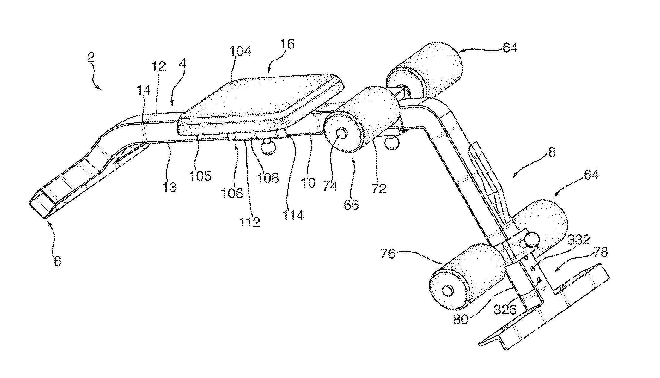
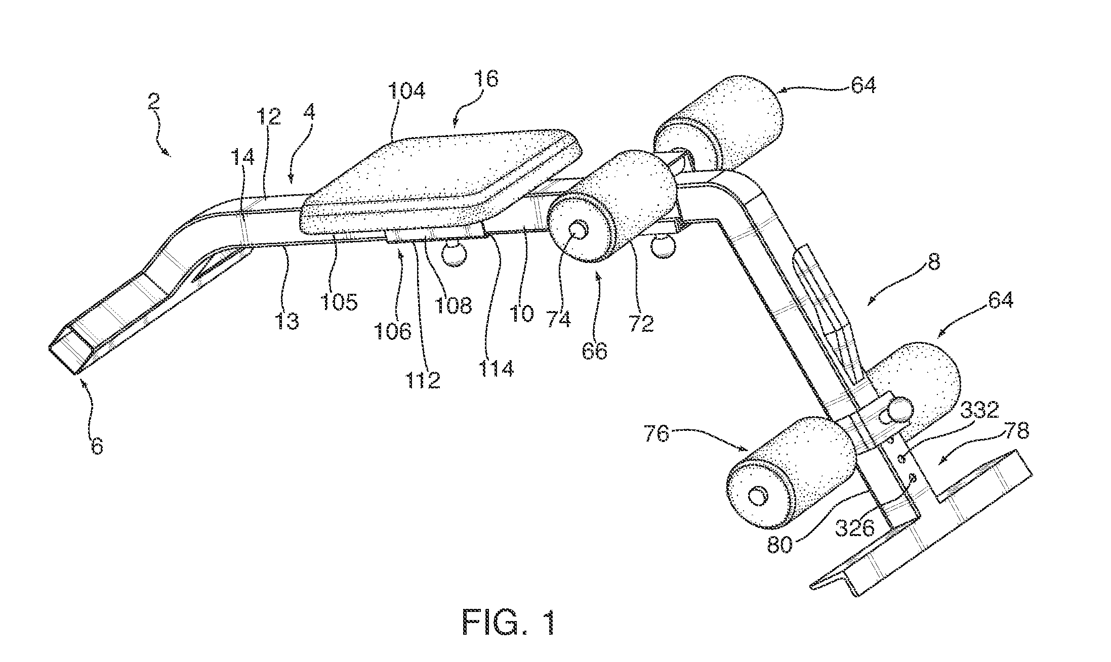
[0017] FIG. 1 is a side perspective view of the abdominal squat machine formed in accordance with a preferred embodiment of the present invention.
[0018] FIG. 2 is a side perspective view of the abdominal squat machine formed in accordance with a preferred embodiment of the present invention.
[0019] FIG. 3 is an enlarged front perspective view of the telescoping end of the abdominal squad machine formed in accordance with a first embodiment of the present invention.
[0020] FIG. 4 is an enlarged side perspective view of the handle locking mechanism of the abdominal squat machine formed in accordance with a preferred embodiment of the present invention.
[0021] FIG. 5 is an exploded view of the handle locking mechanism of the abdominal squat machine formed in accordance with a preferred embodiment of the present invention.
[0022] FIG. 6 is an enlarged side perspective view of the adjustment bracket of the abdominal squat machine formed in accordance with a preferred embodiment of the present invention.
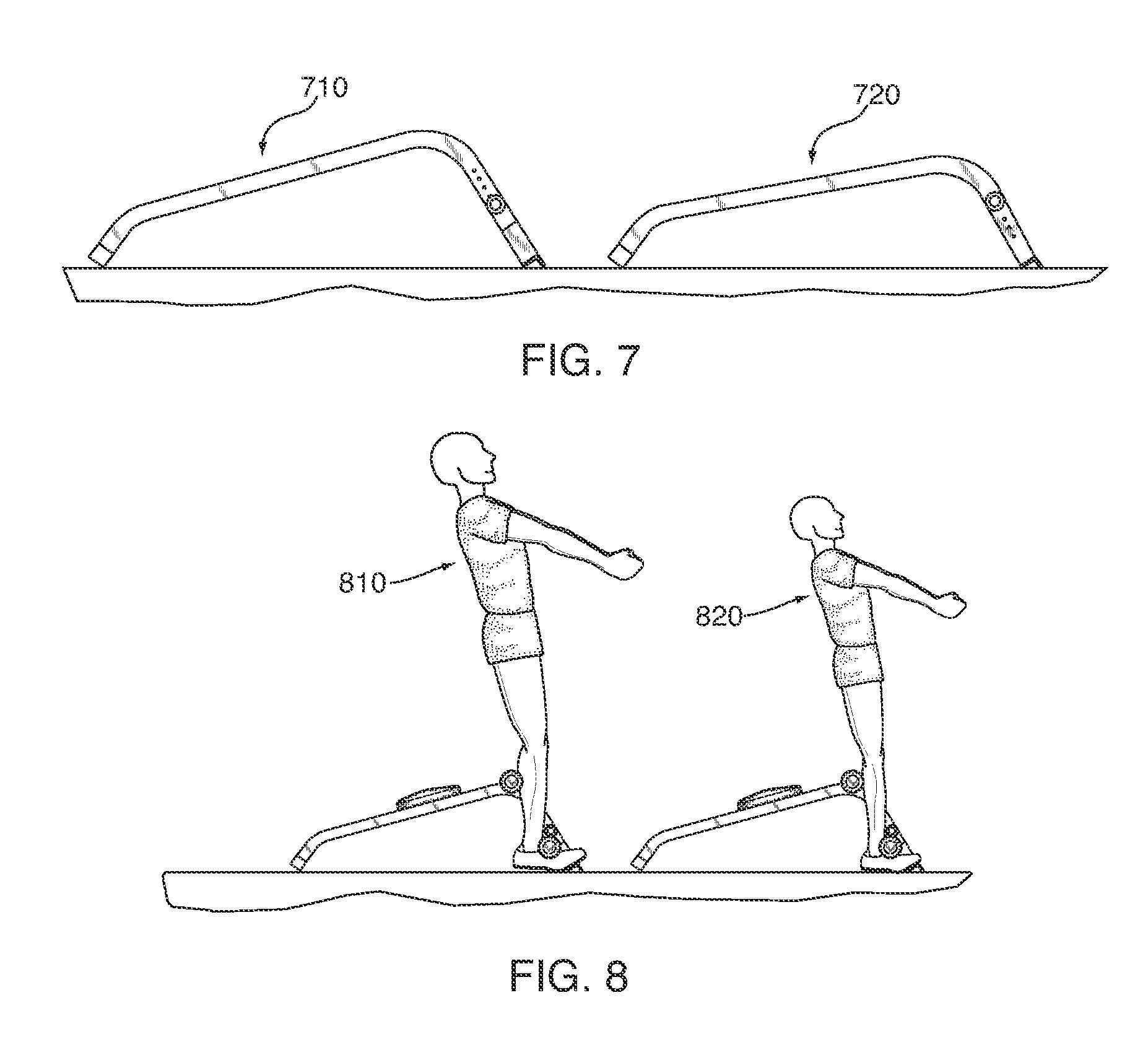
[0023] FIG. 7 is a side view of the abdominal squat machine formed in accordance with a preferred embodiment of the present invention.
[0024] FIG. 8 is a side view of the abdominal squat machine formed in accordance with a preferred embodiment of the present invention.
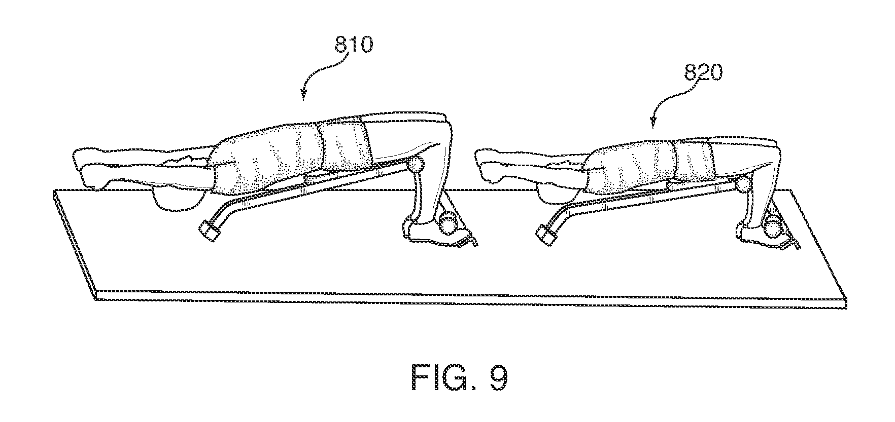
[0025] FIG. 9 is a side perspective view of the abdominal squat machine formed in accordance with a preferred embodiment of the present invention.
[0026] FIG. 10 is a side view of two abdominal squat machines formed in accordance with at least another two embodiments of the present invention, showing the preferred dimensions of the abdominal squat machines in each embodiment.
[0027] FIG. 11 is a side perspective view of the abdominal squat machine with an unstable center of gravity.
[0028] FIG. 12 is a side perspective view of the abdominal squat machine formed in accordance with at least one embodiment of the present invention, showing an unstable center of gravity.
[0029] FIG. 13 is a side perspective view of the abdominal squat machine formed in accordance with a preferred embodiment of the present invention, showing an elongated frame with a stable center of gravity.
[0030] FIG. 14 is a side view of the abdominal squat machine formed in accordance with at least another embodiment of the present invention, showing a slideable second leg securing bar.
DETAILED DESCRIPTION OF THE PRESENT INVENTION
[0031] The present invention provides a combined abdominal and squat machine 2. The abdominal squat machine 2 formed in accordance with the present invention is a passive exercise machine. More specifically, the machine directs resistance to the abdominal muscles and leg muscles of the exerciser by focusing the natural body mass of the user into a training resistance routine without the need of additional weights, pulleys or similar tensioning devices.
[0032] As can be seen in FIG. 1 of the drawings, the abdominal squat machine formed in accordance with the present invention includes a tubular frame 4 having an angulated first end 6 and oppositely disposed angulated telescoping second end 8, interconnected by a primary support member 10. The angulated first end 6, being preferably relatively shorter in length than the second end 8, is angled outwardly in relation to the primary support member 10. The longer telescoping second end 8 is also preferably outwardly angled in relation to the primary support member 10, opposite the angle of the first end 6, to orient the primary support member 10 in a slightly declined manner in a direction from the second end 8 to the first end 6, as illustrated in FIG. 1 of the drawings.
[0033] The primary support member 10 further includes a top surface 12, oppositely disposed bottom surface 13 and side surfaces 14; the top surface 12, bottom surface 13 and side surfaces 14 defining an internal bore 15 (not shown). A seat 16 may be selectively adjusted and engaged along a track portion 18 formed along the length of the primary support member 10. The seat 16 and track portion 18 may be selectively coupled together by engaging a pin 100 into one of a plurality of spaced apart holes 102 collinearly positioned along the bottom surface 13 of the primary support member 10, the holes 102 extending through the bottom surface 13 into the internal bore 15 of the primary support member 10.
[0034] More specifically, the seat 16 having a top cushioned surface 104 for supporting a user and a oppositely disposed bottom surface 105, may further include an adjustment bracket 106 extending perpendicularly from the bottom surface 105. The adjustment bracket 106 preferably includes a pair of oppositely disposed sidewalls 108, the sidewalls 108 having a first end 110 (not shown), the first end 110 being in communication with the bottom surface 105 of the seat 16, and a second end 112, the second end 112 extending downwardly from the first end 110. The second ends 112 of the sidewalls 108 may be interconnected by a bottom adjustment plate 114 spanning the separation between sidewalls 108 and having a central bore 116 (not shown) formed therethrough for receiving the pin 100 to permit the nose 120 of the pin 100 to be received by a selected hole 102 of the primary support member 10 in order to selectively lock the adjustment bracket 106 and the seat 16 affixed thereto in a desired position on the track portion 18 of the primary support member 10. The sidewalls 108 and adjustment plate 114 are preferably dimensioned to define therebetween a space 117 (not shown) for receiving the primary support member 10, the adjustment bracket 106 and seat 16 attached thereto thereby being movable along the length of the track portion.
[0035] The adjustment plate 114 further includes an engagement pin collar 124 having a central bore 126 (not shown) for receiving the pin 100, the pin collar 124 being aligned with the central bore 116 of the plate 114 and extending perpendicularly outwardly therefrom. The pin 100 further comprises a handle 118 and a hole engagement nose 120, the hole engagement nose 120 being interconnected to the handle by a shaft 122, the shaft 122 being received by and axially movable within the collar 124. The handle 118, being axially extendable from a distal end 128 (not shown) of the collar 124, may be pulled downwardly to compress a conical spring 132 surrounding a portion of the shaft extending from the central bore between the adjustment plate 114 and the hole engagement nose 120, the hole engagement nose 120 thereby being moveable within a space between the track portion 18 and the adjustment plate 114. The conical spring 132, in an uncompressed state, provides an upward force on the hole engagement nose 120, pushing it towards the bottom surface 13 of the primary support member 10 and track portion 18. Alternatively, the handle 118 may be axially refracted from the collar 124, pulling the hole engagement nose 120 downwardly towards the adjustment plate 114 and thereby compressing the conical spring 132.
[0036] The seat 16 and adjustable bracket 106 attached thereto may be selectively moved along the track portion 18 to a desired position conforming to the user's body size by retracting the handle 118 of pin 100 outwardly to disengage the hole engagement nose 120 from a hole 102 within the track portion 18. For example, a taller user might find it necessary to move the seat 16 further towards the first end 6 of the frame 4, while a smaller user might position the seat 16 relatively closer to the telescoping end 8 of the frame 4. Once such a position is found, the central bore 116 of the adjustment plate 114 is aligned with one of the holes 102 of the track portion 18 and the handle 118 is released. The conical spring 132, now in an uncompressed state, forces the hole engagement nose 120 into an aligned hole 102, coupling the adjustable bracket 106, and seat 16 attached thereto, to the primary support member 10.
[0037] The telescoping end 8 of the frame 4 includes a top surface 44, oppositely disposed bottom surface 46 and a pair of side walls 48, defining an inner bore 50 for receiving a telescoping member 52. The telescoping member 52 having a first end 54, oppositely disposed second end 78, and a pair of parallel sidewalls 49, the telescoping member 52 being extendable and retractable within the central bore 50 of the telescoping end 8. Preferably, the telescoping member 52 is slightly longer than the telescoping end 8. The telescoping member 52 further includes a support member 58 perpendicularly affixed to the second end 78 thereof. The support member 58 is preferably L-shaped and provides horizontal stabilization to the frame 4 (e.g., by engaging the ground, a surface, etc.). The support member 58 has at least one end 56 thereof (best seen in FIG. 3).
[0038] In a first embodiment of the present invention, as shown in FIGS. 3 and 7 of the drawings, the telescoping member 52 may be extended or retracted from the telescoping end 8 to increase or decrease the degree of declination of the primary support member 10 and adjusted based upon the height of the user. For example, a 6'6'' user 810 (best seen in FIG. 8) may employ the apparatus in the highest position 710 (best seen in FIGS. 7-8), and a 5'4'' user 820 (best seen in FIG. 8) may employ the apparatus in the lowest position 720 (best seen in FIGS. 7-8). The telescoping member 52 and telescoping end 8 may be coupled together by engaging a pin 60 in one of a plurality of spaced apart holes 62 collinearly located through the side walls 48 of the telescoping end 8 and through a pair of holes 51 in the parallel side walls 49 of the telescoping member 52. More specifically, the telescoping member 52 is extended or retracted to a desired amount and the holes 62 through the telescoping end 8 and telescoping member 52 are aligned. The pin 60 is inserted through the aligned holes, coupling the telescoping end 8 and telescoping member 52, limiting further extension and/or retraction.
[0039] In a preferred embodiment of the present invention, the telescoping end 8 may include a handle locking mechanism 90, as shown in FIGS. 1-5 of the drawings. As shown in FIGS. 4 and 5, the handle locking mechanism 90 is assembled on the top surface 44 of the telescoping end 8. In an engaged state, the locking mechanism 90 couples the telescoping end 8 with the telescoping member 52, limiting extension and/or retraction.
[0040] More specifically, the handle locking mechanism 90 includes a handle 92, the handle having a first end 94 and an oppositely disposed second end 96. The handle 92 is preferably pivotally attached to a pair of mounting posts 98 extending perpendicularly from the top surface 44 of the telescoping end 8. The mounting posts 98 further include a pair of holes 300 at a free-end 302 thereof. The handle 92, further including a bottom surface 304, top surface 306, and opposite sidewalls 308, is pivotally attached to the mounting posts 98 by inserting a pin 310 through a pair of holes 312 in its sidewalls. A pair of spacers 314 and a spring 316, the spacers 314 being positioned on opposite sides of the spring 316, are aligned with the sidewall holes 312 and mounting post holes 300. Preferably, the spacers 314 and spring 316 are positioned between the two mounting posts 98. The pin 310, having a headed end 318 and oppositely disposed grooved end 320, the ends 318, 320 being interconnected by a shaft 322, is inserted through the sidewall holes 312 of the handle, mounting post holes 300, spacers 314 and spring 316. A locking C-ring 324 is inserted onto the grooved end 320 of the pin 310 exiting the sidewall 308 of the handle, coupling the handle 92 to the telescoping end 8.
[0041] A locking pin 324 extending perpendicularly from the bottom surface 304 of the handle's second end 96 may selectively engage one of a plurality of spaced apart holes 326 collinearly positioned along the top surface 328 of the telescoping member 52, the holes 326 extending through a top surface of the telescoping member 52 into an internal bore 329 therein. More specifically, in an uncompressed state, the force of the spring 316 on the first end of the handle and the top surface 44 of the telescopic end 8 pushes the second end 96 of the handle and locking pin 324 attached thereto inwardly towards the top surface 44. The locking pin 324 is inserted through an engagement hole 330 on the top surface 44 of the telescopic end 8 and into one of the holes 326 on the top surface of the telescoping member 52, coupling the telescoping member 52 to the telescoping end 8. To decouple the telescoping member 52 and telescoping end 8, downward pressure is applied to the first end 94 of the handle to overcome the force of the spring, and the locking pin 324 is removed from the engagement hole 330 and hole 326 in the top surface 328 of the telescoping member.
[0042] A pair of leg securing bars 64 prevents movement of the user's legs during operation, focusing the exercise resistance on the targeted muscles. More specifically, a first leg securing bar 66 is preferably situated to rest on the top surface 12 of the primary support member 10, near to where the telescoping end 8 is joined to the primary support member. The first leg securing bar 66 extends outwardly from each side wall 14 of the primary support member 10 in opposite directions. The first leg securing bar 66 preferably has mounted on the opposite free ends thereof a pair of foam or vinyl pads 72 having a central bore 74 that receives the first leg securing bar 66. More specifically, the foam pads 72 are optimally placed on opposite sides of the first leg securing bar 66 so that they are oriented on opposing sides of the primary support member 10. The foam pads 72 provide comfort to the user and are positioned behind the upper portion of a user's calf muscles.
[0043] A second leg securing bar 76, having structure similar to that of the first leg securing bar 66 and also having foam pads 72 mounted thereon in a similar manner, is positioned along a lower portion 78 of the telescoping member 52, and is preferably situated to rest on a bottom surface 80 thereof. The second leg securing bar 76 is preferably positioned in front of the user's ankles.
[0044] The first leg securing bar 66 and second leg securing bar 76 may be selectively adjustable along the primary support member track portion 18 and a second track portion 332 along the top surface 328 of the telescoping member 52, respectively. More specifically, as shown in FIG. 6 of the drawings, the securing bars 66, 76 each further include an adjustment bracket 206. The adjustment bracket 206 preferably includes a pair of oppositely disposed sidewalls 208, the sidewalls 208 having a first end 210, the first ends 210 being interconnected by a top plate 234, and a second end 212, the second ends 212 extending downwardly from the first ends 210. The second ends 212 of the sidewalls 208 may be interconnected by an adjustment plate 214 having a central bore 216 for receiving a pin 100 to selectively engage adjustment bracket 206 with the track portion 18 on the primary support member 10 and the track portion 332 on the telescoping member 52. The sidewalls 208 and adjustment plate 214 are preferably dimensioned to define a space 215 for receiving the primary support member 10, with respect to the first leg securing bar 66, and telescoping member 52, with respect to the second leg securing bar 76, the adjustment brackets 206 thereby being movable thereon.
[0045] The adjustment plate 214 further includes an engagement pin collar 224 having a central bore 226 (not shown) for receiving the pin 100, the pin collar 224 being aligned with the central bore 216 of the plate 214 and extending perpendicularly outwardly therefrom. The pin shaft 122 is received and axially movable within the collar 224. The handle 118, being axially retractable from a distal end 228 of the collar 224, may be pulled outwardly from the adjustable plate 214 to compress a conical spring 132 surrounding a portion of the shaft extending from the central bore between the adjustment plate 214 and the hole engagement nose 120, the hole engagement nose 120 thereby being moveable within the space 215 between the track portions 18, 332 and the adjustment plates 214.
[0046] With respect to the first leg securing bar 66, the conical spring 132, in an uncompressed state 334 (best seen in FIG. 6), provides a force on the hole engagement nose 120, pushing it towards the bottom surface 13 of the primary support member 10 and track portion 18. Alternatively, the handle 118 may be axially extended from the collar 224, pulling the hole engagement nose 120 downwardly towards the adjustment plate 214 and thereby compressing the conical spring 132.
[0047] The first leg securing bar 66 and adjustable bracket 206 attached thereto may be selectively moved along the track portion 18 to a desired position conforming to the user's body size by pulling the handle 118 of pin 200 outwardly to disengage the hole engagement nose 120 from a hole 102 within the track portion 18. Once such a position is found, the central bore 216 of the adjustment plate 214 is aligned with one of the holes 102 of the track portion 18 and the handle 118 is released. The conical spring 132, now in an uncompressed state, forces the hole engagement nose 120 into an aligned hole 102, coupling the adjustable bracket 206 and first leg securing bar 66 attached thereto to the primary support member 10.
[0048] Similarly, with respect to the second leg securing bar 76, the adjustable bracket 206 may be selectively engaged with one of the plurality of spaced apart holes 326 collinearly positioned along the track portion 332 on the top surface of the telescoping member 52.
[0049] In at least a further embodiment, the second leg securing bar 76, and the bracket 206 therefor, may operate to slide freely along the telescoping second end 8 and/or the telescoping member 52 of the apparatus (e.g., by not using the pin 100, 200 to lock the bracket 206 of the second leg securing bar 76 into the holes 326 along the top surface 328 of the telescoping member 52). Indeed, a user may slide the second leg securing bar 76 and the pads therefor 72 to a predetermined location based on one or more of the user's anatomy, exercise routine, transition between routines, etc., and the second leg securing bar 76 may be freely moved by the user as desired. When the user positions his or her legs and/or ankles proximately to the second leg securing bar 76, the force of such application is sufficient to hold the second leg securing bar 76 and/or the pads 72 in place for the duration of the exercise routine.
[0050] During operation, a user positions the seat 16 to the desired position. Making reference to FIG. 7 of the drawings, the user may extend or retract the telescoping member 52 to a desired position by engaging and/or disengaging the handle locking mechanism 90. Now referencing FIG. 8, the first leg securing bar 66 is positioned to the upper portion of the calf muscle. The second leg securing bar 76 is positioned in front of the ankles while the user's feet are positioned flat on the floor. In at least one or more embodiments, the user may seamlessly transition between the squat position (see e.g., FIG. 8) and the abdominal routine position (see e.g., FIG. 9) while keeping the user's feet in substantially the same position, e.g., the user's feet may be positioned substantially flat on the floor, substantially on the floor, substantially on the floor and partially on a portion of the support member 58, etc. The user 810, 820 may then sit on the seat 16 and decline his body to a start position, as shown in FIG. 9 of the drawings.
[0051] Now referring to FIG. 10 of the drawings, the preferred dimensions of the abdominal squat machine for two embodiments formed in accordance with the present invention are as shown in FIG. 10. As shown in FIG. 10, the first leg securing bar 66 for use with a user's knees may be disposed in a predetermined location, and the first leg securing bar 66 may be disposed in a fixed position such that the first leg securing bar 66 may not move during operation, between routines, for different users, etc. The height 1030 of the left embodiment in FIG. 10 may be about 15 inches; 15 inches-about 175/8 inches; about 175/8 inches (as shown in FIG. 10). The length 1010 of the frame and/or the apparatus of the left embodiment in FIG. 10 may be about 287/8 inches (as shown in FIG. 10); about 287/8 inches-about 401/4 inches; about 401/4 inches. The height 1040 of the right embodiment in FIG. 10 may be about 15 inches (as shown in FIG. 10); 15 inches-about 175/8 inches; about 175/8 inches, and the length 1020 of the frame and/or apparatus of the right embodiment in FIG. 10 may be about 287/8 inches; about 287/8 inches-about 401/4 inches; about 401/4 inches (as shown in FIG. 10).
[0052] As shown in FIGS. 11-13, the center of gravity 1100 of the user is preferably inward of the first end 6. When the center of gravity vector 1100 is not inward of the first end 6 (e.g., is located 9 inches to the left of the first end 6 as shown in FIG. 11), the first end 6 may be moved to a new location (e.g., more than 9 inches to the left, three inches beyond the center of gravity 1100 so that the first end is now twelve inches from its previous position, etc.) such that the first end 6' is now outside of the center of gravity vector 1100. FIG. 12 depicts the center of gravity 1100 being located to the left of the first end 6 such that the user may be in an unstable position. FIG. 13 illustrates the center of gravity 1100 being located within (i.e., to the right of) the first end 6 such that the user is able to exercise in a stable position. Because the apparatus is adjustable in such a fashion, the apparatus allows the user to safely use the apparatus (also referred to as an exercise machine) without the second end 8 lifting off the floor on which the exercise machine rests. The user may employ weights, such as barbells 1120, when using the apparatus 2 as well.
[0053] During the exercise routine of the present invention, the user moves in a single continuous motion from the supine position to the standing position by contracting the target muscles. The user then slowly returns to the declined position by releasing the muscles. The first securing bar 66 and the second securing bar 76 relieve tension on the knees, limiting inadvertent injury. The seamless transition between the supine position and the standing position (and vice versa) permits a user to benefit from the multi-functional exercise apparatus (i.e., the apparatus permits the user to perform various routines, e.g., abdominal and squat routines, whereas the user would otherwise have to use multiple, separate exercise machines to achieve such operation). The user may further benefit by one or more embodiments of the apparatus because the user may perform both the squat and abdominal exercise routines without having to adjust/modify any settings (e.g., the position of first leg securing bar 66, the position of second leg securing bar 76, the position of seat 16, etc.) of the apparatus. Thus, the apparatus is economical because only one apparatus is needed to perform abdominal and squat routines, and the apparatus provides ease of use for a user since settings do not need to be modified when transitioning between such routines.
[0054] As shown in FIG. 14, the second leg securing bar 76 of the apparatus 2 may operate to be freely slideably engaged with the second end 8 of the frame 4 and/or the telescoping member 52 when no lateral force or pressure is applied thereto. The second leg securing bar 76 of the apparatus 2 may operate to be retained in a predetermined second location when a lateral force or pressure is applied by the one or more legs of the user. The second leg securing bar 76 may operate to be slideably adjustable along a second track portion of the telescoping member 52. For example, in at least one embodiment, the second leg securing bar 76 may be attached to a bracket 208, and bracket 208 may slide freely on the second 8 of the frame 4 and/or the telescoping member 52 (e.g., no pin 100 retains the bracket 208 in place, the bracket 208 is not fastened/secured in place without the lateral force or pressure provided by the legs, ankles, shins, etc. of the user of the apparatus 2, etc.). Additionally, the first leg securing bar 66 may permanently affixed to the frame 4 (e.g., to support member 10 of frame 4) in the predetermined first location.
[0055] Although the invention herein has been described with reference to particular embodiments, it is to be understood that these embodiments are merely illustrative of the principles and applications of the present invention. It is therefore to be understood that numerous modifications may be made to the illustrative embodiments and that other arrangements may be devised without departing from the spirit and scope of the present invention.
* * * * *
D00000
D00001
D00002
D00003
D00004
D00005
D00006
D00007
D00008
D00009
D00010
D00011
XML
uspto.report is an independent third-party trademark research tool that is not affiliated, endorsed, or sponsored by the United States Patent and Trademark Office (USPTO) or any other governmental organization. The information provided by uspto.report is based on publicly available data at the time of writing and is intended for informational purposes only.
While we strive to provide accurate and up-to-date information, we do not guarantee the accuracy, completeness, reliability, or suitability of the information displayed on this site. The use of this site is at your own risk. Any reliance you place on such information is therefore strictly at your own risk.
All official trademark data, including owner information, should be verified by visiting the official USPTO website at www.uspto.gov. This site is not intended to replace professional legal advice and should not be used as a substitute for consulting with a legal professional who is knowledgeable about trademark law.