Putter Head
NARITA; Tadahiro ; et al.
U.S. patent application number 13/165357 was filed with the patent office on 2011-12-29 for putter head. This patent application is currently assigned to BRIDGESTONE SPORTS CO., LTD.. Invention is credited to Wataru BAN, Tadahiro NARITA.
| Application Number | 20110319189 13/165357 |
| Document ID | / |
| Family ID | 45353058 |
| Filed Date | 2011-12-29 |


| United States Patent Application | 20110319189 |
| Kind Code | A1 |
| NARITA; Tadahiro ; et al. | December 29, 2011 |
PUTTER HEAD
Abstract
A putter head includes a head main body having a depressed portion and a face insert disposed within the depressed portion so that the face insert is mounted in a face surface of the head main body. The face insert includes at least one low hardness portion and at least one high hardness portion. The face insert has a boundary face between the at least one low hardness portion and the at least one high hardness portion which is inclined relative to a back-to-forth direction of the putter head. The boundary face may decline toward the rear or may rise toward the rear. The face insert may comprise a plurality of the low hardness portions and a plurality of the high hardness portions so that the low and high hardness portions are arranged vertically in multiple layers. The sectional shapes taken perpendicularly to the back-to-forth direction of the high hardness portion and the low hardness portion may be substantially of a right triangle. The face insert may comprise a surface layer and groove portions on a front face thereof.
| Inventors: | NARITA; Tadahiro; (Chichibu-shi, JP) ; BAN; Wataru; (Chichibu-shi, JP) |
| Assignee: | BRIDGESTONE SPORTS CO.,
LTD. Tokyo JP |
| Family ID: | 45353058 |
| Appl. No.: | 13/165357 |
| Filed: | June 21, 2011 |
| Current U.S. Class: | 473/340 |
| Current CPC Class: | A63B 53/0445 20200801; A63B 53/0458 20200801; A63B 2209/00 20130101; A63B 53/0416 20200801; A63B 60/54 20151001; A63B 53/0425 20200801; A63B 53/0487 20130101 |
| Class at Publication: | 473/340 |
| International Class: | A63B 53/04 20060101 A63B053/04 |
Foreign Application Data
| Date | Code | Application Number |
|---|---|---|
| Jun 29, 2010 | JP | 2010-147856 |
Claims
1. A putter head comprising: a head main body; and a face insert mounted in a face surface of the head main body, the face insert comprising at least one low hardness portion and at least one high hardness portion, wherein the face insert has a boundary face between the at least one low hardness portion and the at least one high hardness portion which is inclined relative to a back-to-forth direction of the putter head.
2. The putter head according to claim 1, wherein the face insert comprises a plurality of the low hardness portions and a plurality of the high hardness portions so that the low hardness portions and the high hardness portions are arranged in multiple layers along a direction from a top side to a sole side of the putter head.
3. The putter head according to claim 2, wherein the face insert further comprises a surface layer of synthetic resin or metal on a front face of the face insert.
4. The putter head according to claim 2, wherein each of the plurality of the high hardness portions is separated from a front face of the face insert by the low hardness portions so that two low hardness portions adjacent to the high hardness portion are combined with each other before a front edge of the high hardness portion and the plurality of the low hardness portions are continuous with each other.
5. The putter head according to claim 2, wherein the face insert comprises groove portions formed in a front face of the face insert, the groove portions reaching each front edge portion of the plurality of the high hardness portion which recedes relative to each front face of the plurality of the low hardness portions.
6. The putter head according to claim 1, wherein the boundary face declines toward the rear.
7. The putter head according to claim 1, wherein the boundary face rises toward the rear.
8. The putter head according to claim 1, wherein the head main body has a depressed portion in which the face insert is disposed so that a side surface around the face insert is apart from a side surface of the depressed portion.
9. The putter head according to claim 8, further comprising a viscoelastic material applied between the side surface of the face insert and the side surface of the depressed portion.
Description
CROSS-REFERENCE TO RELATED APPLICATION
[0001] This Application claims priority from Japanese Patent Application No. 2010-147856 filed Jun. 29, 2010, which is incorporated herein by reference in its entirety.
BACKGROUND OF THE INVENTION
[0002] The present invention relates to a putter head for a putter for golf, and more particularly, relates to a putter head including a face insert mounted in a face surface of a head main body thereof.
[0003] The putter for golf is a club for use mainly for hitting a ball on a green to roll the ball toward a cup. The putter head may be constructed so as to soften a feeling of putting by mounting a face insert in a face surface thereof.
[0004] Japanese Unexamined Patent Application Publication No. 2007-117635 describes an invention that the face insert is constructed of a high hardness portion and a low hardness portion whereas the high hardness portion is formed such that a thickness thereof decreases gradually from its central portion to its peripheral portion. A putter head using this face insert has a characteristic that the feeling of putting is soft and a putting sound is high.
SUMMARY OF THE INVENTION
[0005] An object of the present invention is to provide a putter head which ensures an excellent straight advancement of a hit ball.
[0006] To achieve the above-described object, according to the present invention, there is provided a putter head having a head main body and a face insert mounted in a face surface of the head main body, the face insert having at least one low hardness portion and at least one high hardness portion, in which the face insert has a boundary face between the at least one low hardness portion and the at least one high hardness portion which is inclined relative to a back-to-forth direction of the putter head.
[0007] The face insert may include a plurality of the low hardness portions and a plurality of the high hardness portions so that the low hardness portions and the high hardness portions can be arranged in multiple layers along a direction from a top side to a sole side of the putter head.
[0008] The face insert may further include a surface layer of synthetic resin or metal on a front face of the face insert.
[0009] Each of the plurality of the high hardness portions may be separated from a front face of the face insert by the low hardness portions so that two low hardness portions adjacent to the high hardness portion can be combined with each other before a front edge of the high hardness portion and the plurality of the low hardness portions can be continuous with each other.
[0010] The face insert may have groove portions formed in a front face of the face insert, the groove portions reaching each front edge portion of the plurality of the high hardness portion which recedes relative to each front face of the plurality of the low hardness portions.
[0011] The boundary face may decline toward the rear.
[0012] The boundary face may rise toward the rear.
[0013] The head main body may have a depressed portion in which the face insert is disposed so that a side surface around the face insert can be apart from a side surface of the depressed portion.
[0014] The putter head may further include a viscoelastic material applied between the side surface of the face insert and the side surface of the depressed portion.
[0015] In the face insert of the putter head of the present invention, because the boundary face between the low hardness portion and the high hardness portion is inclined relative to the back-to-forth direction of the putter head, the spin such as overspin and backspin of the hit ball can be improved.
[0016] When the low hardness portions and the high hardness portions are arranged vertically in multiple layers as mentioned above, even if there are variations in ball hitting position in a vertical direction, variations of the spin improvement mentioned above can be eliminated.
[0017] When the surface layer of synthetic resin or metal is provided on the front face of the face insert as mentioned above, the feeling of putting a ball can be adjusted by selecting material of the synthetic resin. Additionally, it is easy to form an entire surface of the face with an even appearance.
[0018] In cases in which a low hardness portion above the high hardness portion and a high hardness portion under the high hardness portion are combined with each other before a front edge of the high hardness portion such that both the low hardness portions are continuous with each other as mentioned above, the same advantage can be secured.
[0019] By forming the groove portions in the front face of the face insert as mentioned above, spin becomes likely to be applied to a ball.
[0020] When the face surface of the head main body is provided with the depressed portion and the face insert is disposed within this depressed portion, by providing a gap around the face insert and applying viscoelastic material therein, there is an effect of preventing deformation of the face insert containing differences in hardness and having an inclined boundary face therein from being suppressed.
BRIEF DESCRIPTION OF THE DRAWINGS
[0021] FIG. 1(A) is an exploded perspective view of a putter head according to an embodiment of the present invention;
[0022] FIG. 1(B) is a front view of the putter head of FIG. 1(A);
[0023] FIG. 1(C) is a sectional view taken along the line C-C of FIG. 1(B);
[0024] FIG. 2 is a sectional view taken along the line II-II of FIG. 1(A);
[0025] FIG. 3 is a sectional view of a face insert of a putter head according to another embodiment;
[0026] FIG. 4 is a sectional view of the face insert of a putter head according to another embodiment;
[0027] FIG. 5(A) is a perspective view of the face insert of a putter head according to another embodiment;
[0028] FIG. 5(B) is a sectional view taken along the line B-B of FIG. 5(A);
[0029] FIG. 6 is a sectional view of the face insert of a putter head according to another embodiment;
[0030] FIG. 7 is a sectional view of the face insert of a putter head according to another embodiment;
[0031] FIG. 8 is a sectional view of the face insert of a putter head according to another embodiment;
[0032] FIG. 9 is a sectional view of the face insert of a putter head according to another embodiment;
[0033] FIG. 10 is a sectional view of the face insert of a putter head according to another embodiment;
[0034] FIG. 11 is a sectional view of a putter head according to another embodiment;
[0035] FIG. 12(A) is a front view of a putter head according to another embodiment; and
[0036] FIG. 12(B) is a sectional view taken along the line B-B of FIG. 12(A).
DETAILED DESCRIPTION OF PREFERRED EMBODIMENTS
[0037] Hereinafter, embodiments of the present invention will be described in detail with reference to the accompanying drawings.
[0038] FIGS. 1 and 2 indicate a putter head 1 according to a first embodiment. This putter head 1 is provided with a depressed portion 2H in the front face (face surface) of a head main body 2 and a face insert 3 is disposed within this depressed portion 2H. According to this embodiment, the head main body 2 is made of metal. A front face of the face insert 3 is flush with a front face of the head main body 2 around the depressed portion 2H.
[0039] The depressed portion 2H and the face insert 3 are of a substantially rectangular shape which is horizontally long. The depth of the depressed portion 2H is entirely even and the thickness of the face insert 3 is entirely even. However, they may be provided partly with a deep portion or a thick portion or may be provided partly with a shallow portion or a thin portion.
[0040] The lateral and vertical widths of the face insert 3 are slightly smaller than those of the depressed portion 2H and there is a slight gap 4 between top, bottom, right and left side faces 3S of the face insert 3 and the peripheral face 2S of the depressed portion 2H. Preferably, the width of this gap 4 is 0.1 to 1 mm, particularly 0.2 to 0.8 mm. Regarding the size of the face insert 3, the vertical width is preferred to be 16 to 30 mm, particularly 18 to 25 mm, the lateral width is preferred to be 50 to 150 mm, particularly 70 to 100 mm and the thickness is preferred to be 2 to 10 mm, particularly 3 to 6 mm. However, they are not limited to these values.
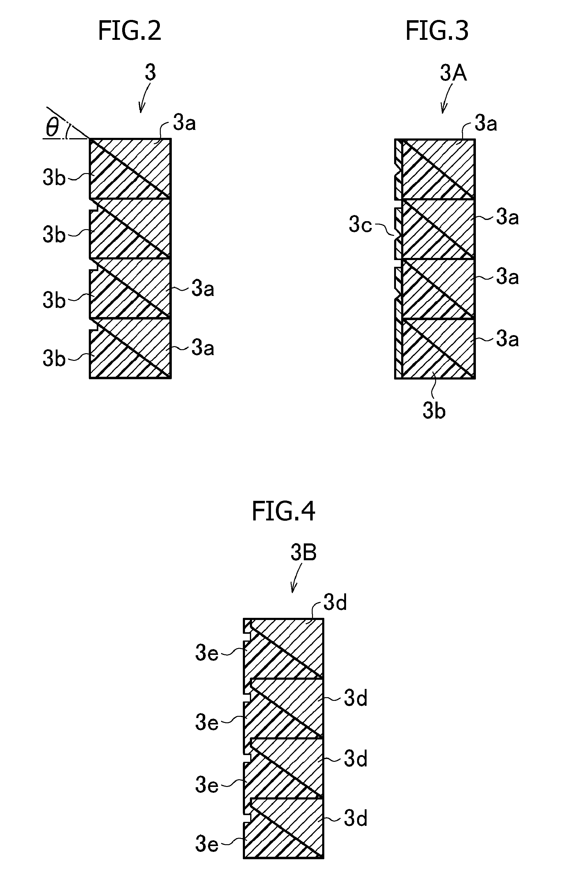
[0041] As shown in FIG. 2, this face insert 3 includes high hardness portions 3a, each having a rear face of the insert, and low hardness portions 3b, each having a front face of the insert, which are stacked alternately vertically (i.e., along the direction from a top side to a sole side of the putter head) into multiple layers. In this embodiment, four layers of the high hardness portions 3a and four layers of the low hardness portions 3b are provided such that the high hardness portion is located up and the low hardness portion is located down in each layer, thereby totaling eight layers. This total number of layers is preferred to be 20 or less, particularly 6 to 14.
[0042] In this embodiment, the sectional shapes taken perpendicularly to the back-to-forth direction of the high hardness portion 3a and the low hardness portion 3b are substantially of a right triangle. A front end of the high hardness portion 3a reaches the front face of the face insert 3. A boundary face between the high hardness portion 3a and the low hardness portion 3b is an inclined face which declines toward the rear. The declining gradient .theta. of this inclined face is preferred to be 20.degree. to 86.degree., particularly 30.degree. to 84.degree.. As a result, as compared to ordinary putters, the degree of backspin (i.e., inverse rotation) when a ball is hit is reduced and straight advancement is improved.
[0043] As material of the high hardness portion 3a, hard plastic or synthetic resin such as polyester, nylon and urethane and metal such as aluminum, titanium, copper and alloys thereof are preferable. As material of the low hardness portion 3b, materials having elasticity such as thermoplastic elastomer and rubber are preferable. The face insert 3 may be produced by connecting the high hardness portion 3a and the low hardness portion 3b together by bonding or welding. Alternatively, it is permissible to dispose the high hardness portion 3a within a mold and insert-mold the low hardness portion 3b by injecting corresponding material into the mold.
[0044] The face insert 3 is disposed within the depressed portion 2H with a left side face in FIG. 2 as a front side of a putter face, and its opposite side is bonded to a deep wall face of the depressed portion 2H with adhesive. Although as the adhesive, epoxide-based adhesive, rubber-based adhesive and the like are preferred, it is not limited to these adhesives. It is possible to use a double-faced tape.
[0045] A putter is constructed by connecting a shaft to a hosel portion 1h of the putter head 1 having the above-described construction. When a ball is putted with this putter (a ball on the green is putted with a face surface), the face surface of the putter strongly pushes an upper area of the ball so that overspin is likely to be applied to the ball because of the above-mentioned inclined face, whereby straight advancement of the hit ball is improved.
[0046] According to the present invention, as shown in a face insert 3A of FIG. 3, a surface layer 3c of thin synthetic resin may be provided on an entire front face of the face insert by bonding or welding. As synthetic resin of this surface layer 3c, an elastomer is preferable. The thickness of the surface layer 3c of synthetic resin is preferred to be 0.2 to 1.0 mm. The other configuration of FIG. 3 is the same as FIG. 2 and the same reference numerals indicate the same portions. By providing this synthetic resin surface layer 3c, the entire front face of the face insert 3A has a uniform appearance. Furthermore, the hardness of the surface of a face insert can be a desired one.
[0047] According to the present invention, as shown in a face insert 3B of FIG. 4, the front end of a high hardness portion 3d may be separated from the front face of the face insert 3B, and a low hardness portion 3e above the high hardness portion 3d and a high hardness portion 3e under the same high hardness portion 3d may be combined with each other before a front edge of the high hardness portion 3d such that both the low hardness portions are continuous with each other. This face insert 3B also has a uniform appearance because its face surface is constructed uniformly of the low hardness portion 3e. In the meantime, the high hardness portion 3d has the same structure as the high hardness portion 3a except that it is of a trapezoidal shape in cross section, lacking the front end of the high hardness portion 3a. The low hardness portion 3e has the same structure as the low hardness portion 3b except that the low hardness portions 3e adjacent vertically are combined with each other.
[0048] According to the present invention, as shown in a face insert 3C of FIG. 5, the face surface may be provided with horizontally long groove portions 3g. The groove portions 3g are provided except near the right end and the left end of the face insert 3C. Additionally, the face inserts 3A, 3B, 3C may be provided with the groove portions. The face insert 3C is formed by providing the groove portions 3g in the face insert 3B of FIG. 4 such that they reach the front ends of the high hardness portion 3d. The groove portion 3g has a trapezoidal shape in which the vertical width of an inlet of the groove portion 3g is large while the vertical width of the deepest portion of the groove portion 3g is the smallest. Provision of the groove portions 3g facilitates application of spin to a ball. The other configuration of the face insert 3C is the face insert 3B and the same reference numerals indicate the same portions.
[0049] The vertical width of the inlet of the groove portion 3g is preferred to be 0.3 to 1.6 mm, particularly 0.4 to 0.8 mm, and the depth of the groove portion is preferred to be 0.05 to 1.1 mm, particularly 0.07 to 0.5 mm. Although the grooves may have only the same cross section, they may have multiple kinds of cross sections.
[0050] In the above-described embodiments, the face insert is so constructed that the high hardness portions and the low hardness portions are provided as a set vertically in multiple layers. However, as shown in a face insert 3D of FIG. 6, it is permissible to provide each of a high hardness portion 3h and a low hardness portion 3i. Both the high hardness portion 3h and the low hardness portion 3i are of a right triangle and the rectangular parallelepiped face insert 3D is formed by bonding or welding together faces corresponding to the inclined faces of the respective right triangles.
[0051] Because the thickness of the low hardness portion 3i in the back-to-forth direction of the head (width in a right-to-left direction of the low hardness portion 3i in FIG. 6) decreases toward the top of the head, when a ball is hit with a putter having this face insert 3D, a higher position of the head can apply a stronger repelling force to the ball, and thereby, overspin is applied to the ball easily.
[0052] Although according to the above-described embodiments, the boundary face between the low hardness portion and the high hardness portion is inclined such that it descends toward the rear of the head, conversely, the boundary face may be inclined such that it rises toward the rear of the head.
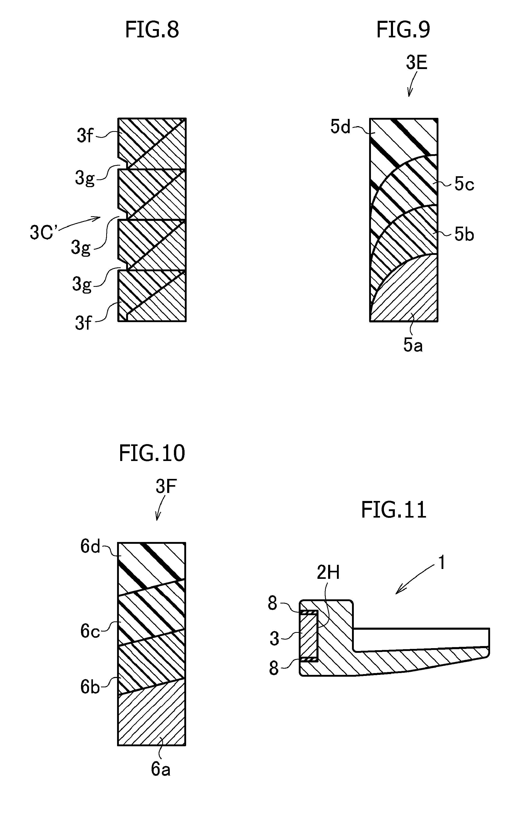
[0053] A face insert 3' of FIG. 7 is obtained by turning the face insert 3 of FIG. 2 upside down. A face insert 3C' of FIG. 8 is obtained by turning the face insert 3C of FIG. 5 upside down. The other configurations of both cases are the same as FIG. 2 and FIG. 5 and the same reference numerals indicate the same portions. Furthermore, the face inserts may be obtained by turning the face inserts 3A, 3B, and 3C upside down.
[0054] When a ball is hit with a putter having the face inserts 3', 3C', back spin becomes likely to be applied to the ball due to an effect in which the loft angle is increased by the inclined face, thereby preventing the ball from rolling easily.
[0055] In a face insert 3E of FIG. 9, with a high hardness portion 5a having the highest hardness being disposed on a bottom thereof, a medium high hardness portion 5b, a medium low hardness portion 5c and a low hardness portion 5d are disposed in order thereabove such that the hardness decreases sequentially. The top faces of the high hardness portion 5a, the medium high hardness portion 5b and the medium low hardness portion 5c are of a quarter-circle curve which projects upward and forward. The bottom faces of the medium high hardness portion 5b, the medium low hardness portion 5c and the low hardness portion 5d are of quarter-circle curve which recedes relative downwardly and backwardly. The face insert 3E is of a rectangular parallelepiped shape like the above-described face inserts. The boundary faces between the high hardness portion 5a to the low hardness portion 5d becomes higher toward the rear.
[0056] In a face insert 3F of FIG. 10, a high hardness portion 6a, a medium high hardness portion 6b, a medium low hardness portion 6c and a low hardness portion 6d are arranged such that the hardness decreases in a sequence from the bottom to the top. The high hardness portion 6a and the low hardness portion 6d have a trapezoidal cross section and the medium high hardness portion 6b and the medium low hardness portion 6c have a parallelogram cross section. The face insert 3F is of a parallelogram shape like the above-described respective face inserts. The boundary faces between the high hardness portion 6a to the low hardness portion 6d rise toward the rear.
[0057] When a ball is hit with a putter having the face inserts 3E, 3F of FIG. 9 and FIG. 10, back spin becomes likely to be applied to the ball, because of an increased loft angle. In particular, when the green has unkempt grass, a putting distance can be easily controlled by using the putter having the face inserts 3E, 3F, and straight advancement of the hit ball can be improved. Although the boundary face rises toward the rear in FIG. 9 and FIG. 10, conversely, the boundary face may be decreased toward the rear.
[0058] Although referring to FIG. 1, the gap 4 is formed around the face insert 3, it is possible to dispose viscoelastic material 8 such as rubber, elastomer, or synthetic resin in this gap as shown in FIG. 11. As shown in a putter head 1' of FIG. 12, it is possible to construct the face insert 3 so as to fit to the depressed portion 2H without any gap 4.
[0059] Other configurations in FIG. 11 and FIG. 12 are the same as FIG. 1, and the same reference numerals indicate the same portions. Provision of the gap 4 or the viscoelastic material 8 eliminates generation of residual stress in the face insert, thereby ensuring an effect that rebound characteristics of the face insert are obtained as designed.
* * * * *
D00000
D00001
D00002
D00003
D00004
D00005
XML
uspto.report is an independent third-party trademark research tool that is not affiliated, endorsed, or sponsored by the United States Patent and Trademark Office (USPTO) or any other governmental organization. The information provided by uspto.report is based on publicly available data at the time of writing and is intended for informational purposes only.
While we strive to provide accurate and up-to-date information, we do not guarantee the accuracy, completeness, reliability, or suitability of the information displayed on this site. The use of this site is at your own risk. Any reliance you place on such information is therefore strictly at your own risk.
All official trademark data, including owner information, should be verified by visiting the official USPTO website at www.uspto.gov. This site is not intended to replace professional legal advice and should not be used as a substitute for consulting with a legal professional who is knowledgeable about trademark law.