Gas Compressor And Method For Controlling Flow Rate Thereof
Jeong; Kyu-Ok ; et al.
U.S. patent application number 13/254250 was filed with the patent office on 2011-12-29 for gas compressor and method for controlling flow rate thereof. This patent application is currently assigned to AIRZEN CO.,LTD. Invention is credited to Hyun-Wook Jeong, Jin-Wook Jeong, Kyu-Ok Jeong.
| Application Number | 20110318182 13/254250 |
| Document ID | / |
| Family ID | 42710129 |
| Filed Date | 2011-12-29 |
View All Diagrams
| United States Patent Application | 20110318182 |
| Kind Code | A1 |
| Jeong; Kyu-Ok ; et al. | December 29, 2011 |
GAS COMPRESSOR AND METHOD FOR CONTROLLING FLOW RATE THEREOF
Abstract
Provided is a gas compressor with a variable diffuser system capable of suppressing stall and surge. The gas compressor includes i) an impeller fixed to a rotation shaft and having a plurality of blades each including a wing surface and an edge surface on an outer circumferential surface thereof; ii) a shroud surrounding the wing surface; iii) a ring valve installed on a diffuser passage connected with an outlet of the impeller and moving in a direction parallel to the rotation shaft to open and close the diffuser passage; iv) a plurality of veins installed in a circumferential direction of the diffuser passage outside the ring valve in the diffuser passage; and v) an actuator coupled with the ring valve and the plurality of veins to sequentially control movement of the ring valve and rotational angles of the veins.
| Inventors: | Jeong; Kyu-Ok; (Kyungsangnam-do, KR) ; Jeong; Hyun-Wook; (Kyungsangnam-do, KR) ; Jeong; Jin-Wook; (Kyungsangnam-do, KR) |
| Assignee: | AIRZEN CO.,LTD Kimhae-city KR |
| Family ID: | 42710129 |
| Appl. No.: | 13/254250 |
| Filed: | March 4, 2010 |
| PCT Filed: | March 4, 2010 |
| PCT NO: | PCT/KR2010/001361 |
| 371 Date: | September 1, 2011 |
| Current U.S. Class: | 416/183 ; 417/53 |
| Current CPC Class: | F04D 29/462 20130101 |
| Class at Publication: | 416/183 ; 417/53 |
| International Class: | F01D 5/22 20060101 F01D005/22; F04B 49/06 20060101 F04B049/06 |
Foreign Application Data
| Date | Code | Application Number |
|---|---|---|
| Mar 5, 2009 | KR | KR10-2009-0019011 |
| Mar 5, 2009 | KR | KR10-2009-0019013 |
Claims
1. A gas compressor, comprising: an impeller fixed to a rotation shaft and having a plurality of blades each including a wing surface and an edge surface on an outer circumferential surface thereof; a shroud surrounding the wing surface and having an outer wall parallel to the edge surface; and a ring valve installed on a diffuser passage connected with an outlet of the impeller to open and close the diffuser passage and maintaining a gap from the end of the impeller in a radial direction of the impeller, wherein the ring valve slidably moves on the outer wall of the shroud while contacting the outer wall of the shroud.
2. The gas compressor of claim 1, wherein: the ring valve maintains a gap G of a condition described below from the end of the impeller in the radial direction of the impeller, 0.002D.ltoreq.G.ltoreq.0.0080D wherein, D represents a diameter (mm) at the outlet of the impeller.
3. The gas compressor of claim 2, further comprising: a plurality of veins installed in a circumferential direction of the diffuser passage outside the ring valve in the diffuser passage.
4. A gas compressor, comprising: an impeller fixed to a rotation shaft and having a plurality of blades each including a wing surface and an edge surface on an outer circumferential surface thereof; a shroud surrounding the wing surface; a ring valve installed on a diffuser passage connected with an outlet of the impeller and moving in a direction parallel to the rotation shaft to open and close the diffuser passage; a plurality of veins installed in a circumferential direction of the diffuser passage outside the ring valve in the diffuser passage and each having a vein shaft; and an actuator coupled with the ring valve and the plurality of vein shafts to sequentially control movement of the ring valve and rotational angles of the veins.
5. The gas compressor of claim 4, wherein: the ring valve maintains a gap G of a condition described below from the end of the impeller in the radial direction of the impeller, 0.002D.ltoreq.G.ltoreq.0.0080D wherein, D represents a diameter (mm) at the outlet of the impeller.
6. The gas compressor of claim 5, wherein: an outer wall of the shroud is parallel to the edge surface and the ring valve slidably moves on the outer wall of the shroud while contacting the outer wall of the shroud.
7. The gas compressor of claim 6, wherein: in the impeller, spaces among the blades are in communication with each other over the wing surface inside the shroud.
8. The gas compressor of claim 6, wherein: in the impeller, the spaces among the blades are separated from each other by a cover plate on the wing surface.
9. The gas compressor of claim 4, wherein: the actuator includes an inner guide ring surrounding the vein shaft; a plurality of ball levers penetrating the inner guide ring and the vein shaft in the radial direction of the impeller to couple the inner guide ring and the vein shaft with each other; an outer guide ring surrounding the inner guide ring, integrally connected with the ring valve by a connector, and having a slant sliding hole; and a fixing pin fixed to the inner guide ring through the slant sliding hole, wherein the gas compressor further includes a diffuser frame supporting the vein shaft, the inner guide ring, and the ring valve.
10. The gas compressor of claim 9, wherein: the vein shaft has a cavity penetrating the vein shaft in the radial direction of the impeller and the inner guide ring has a plurality of openings facing the cavity in the radial direction of the impeller.
11. The gas compressor of claim 10, wherein: each of the plurality of ball levers includes a ball member closely attached to a side wall of the opening of the inner guide ring and a support member inserted to the cavity to be fixed to the vein shaft.
12. The gas compressor of claim 9, wherein: the actuator further includes a stop member controlling a rotational speed of the inner guide ring; a control handle fixed to the outer guide ring; and an elastic member installed between the diffuser frame and the fixing pin.
13. The gas compressor of claim 12, wherein: the stop member includes a pair of first bars positioned with a distance in the circumferential direction on one surface of the inner guide ring; and a second bar fixed to the diffuser frame and protruding so that a part thereof is positioned between the pair of first bars.
14. The gas compressor of claim 4, wherein: the actuator includes a link member fixed to the vein shaft; a guide shaft fixed to the link member with a distance from the vein shaft; and a control member rotating the vein shaft by moving the guide shaft while forming a first guide groove receiving the guide shaft on one surface thereof.
15. The gas compressor of claim 14, wherein: the first guide groove is formed in the radial direction of the impeller, and the control member further includes a second guide groove formed in a circumferential direction of the control member while being linked with the first guide groove.
16. The gas compressor of claim 15, further comprising: a diffuser frame supporting the ring valve, and the vein shaft and the control member while surrounding the ring valve, wherein in the diffuser frame, the slant sliding hole is formed in a region overlapping with the ring valve.
17. The gas compressor of claim 16, wherein: the control member further includes a third guide groove formed on an inner surface of the control member while being linked with the second guide groove, and the actuator further includes a fixing key of which one end is fixed to the ring valve by penetrating the slant sliding hole and the other end is received in the third guide groove.
18. The gas compressor of claim 16, wherein: in the diffuser frame, a plurality of vein holes which the vein shaft penetrates are formed in a direction parallel to the rotation shaft and the slant sliding hole is spaced apart from the vein hole between two adjacent vein holes.
19. The gas compressor of claim 14, wherein: the control member is connected with a control unit sensing an operational condition of the gas compressor to be operated by a command from the control unit.
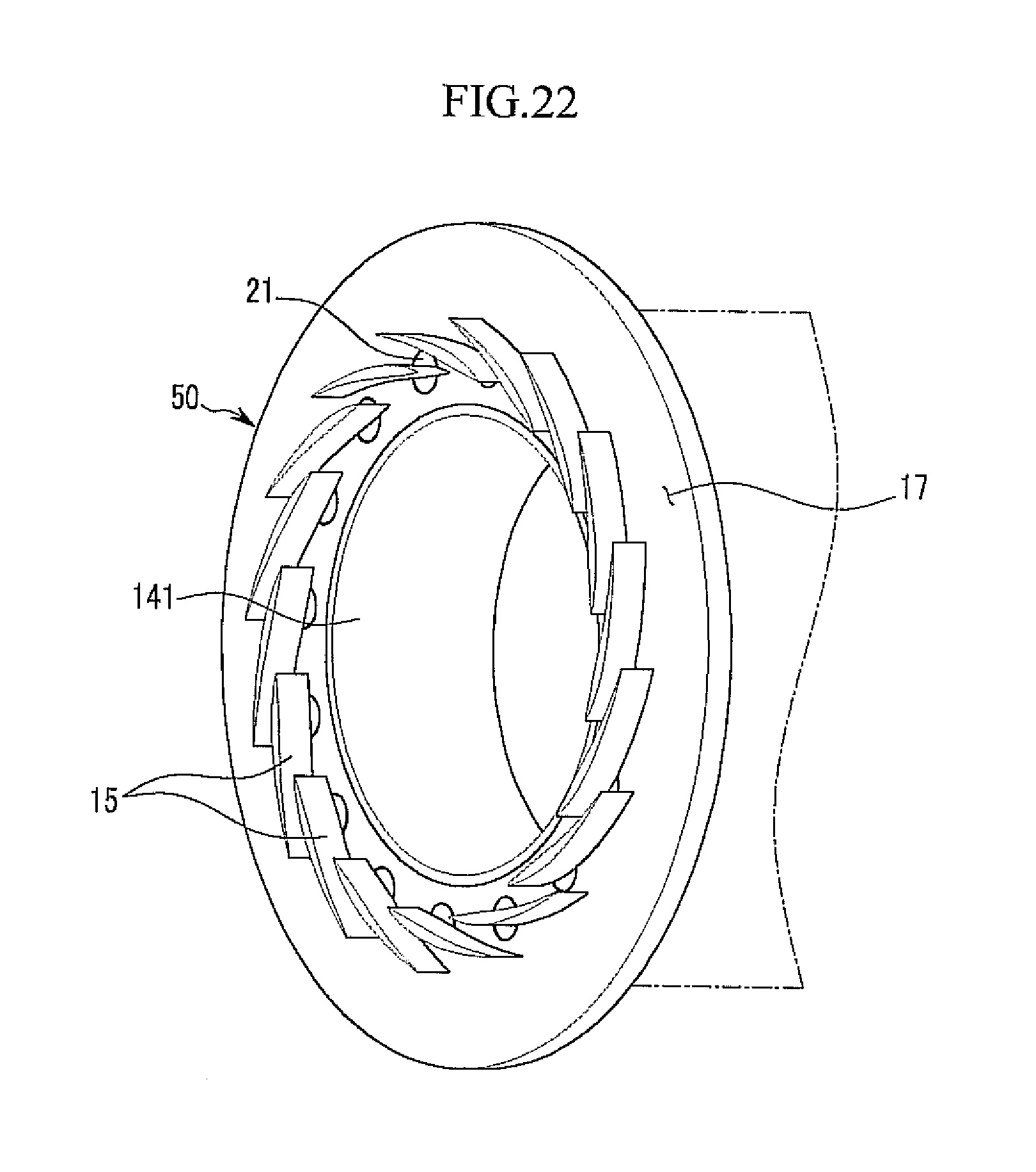
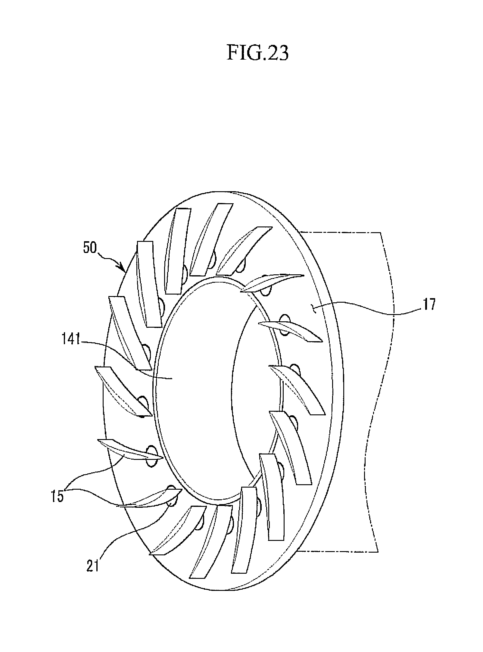
20. The gas compressor of claim 4 wherein: the actuator includes a first actuator coupled with the plurality of vein shafts to control the rotational angles of the veins; and a second actuator coupled with the ring valve to control the movement of the ring valve, and the first actuator includes a link member fixed to the vein shaft; a guide shat fixed to the link member with a distance from the vein shaft; and a control member rotating the vein shaft by moving the guide shaft while forming the first guide groove receiving the guide shaft on one surface thereof.
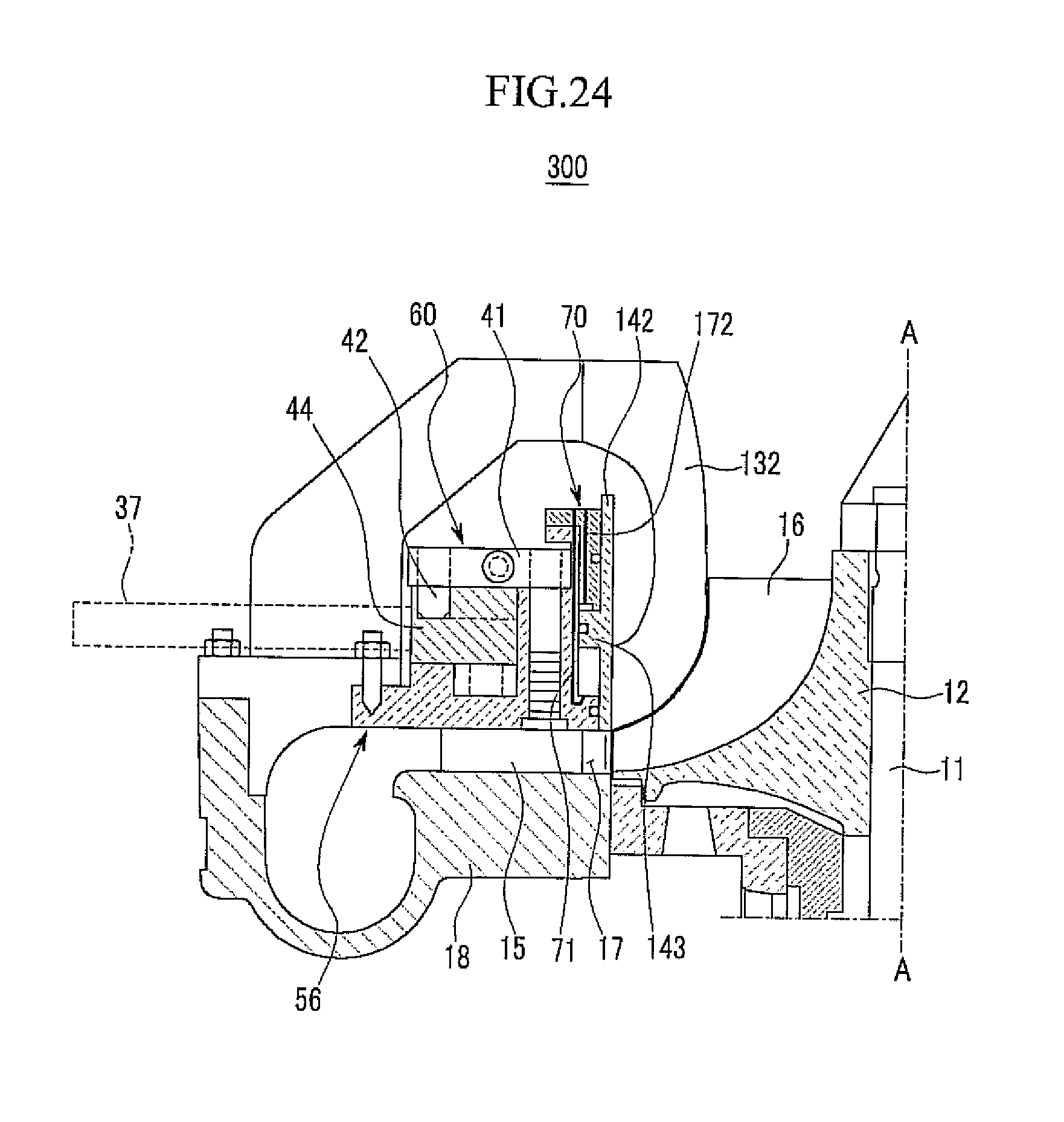
21. The gas compressor of claim 20, wherein: the first guide is formed in the radial direction of the impeller, and the control member further includes a second guide groove formed in the circumferential direction of the control member while being linked with the first guide groove.
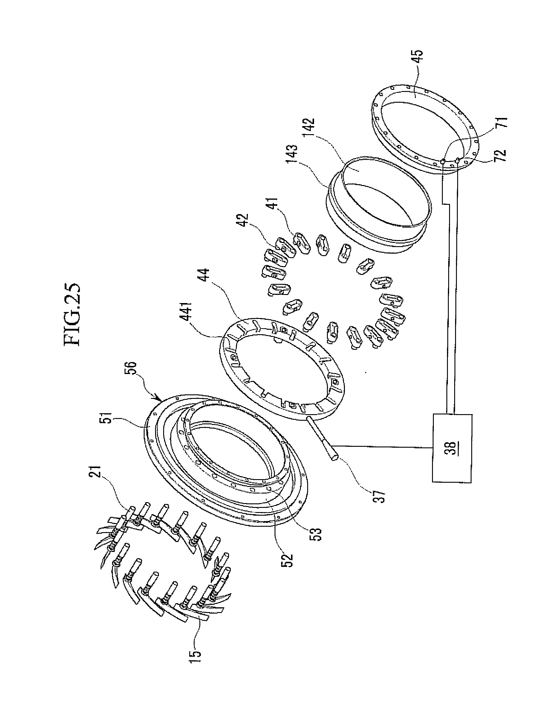
22. The gas compressor of claim 20, wherein: the ring valve has an extension ring on an outer surface thereof, and the second actuator includes a first nozzle spraying compressed air to the one surface of the extension ring toward the diffuser passage; and a second nozzle spraying compressed air to one opposite surface of the extension ring which is faraway from the diffuser passage.
23. The gas compressor of claim 22, further comprising: a top cover installed between the diffuser frame and the ring valve, wherein the first nozzle is formed throughout the top cover and the diffuser frame and the second nozzle is formed on the top cover.
24. The gas compressor of claim 22, wherein: the control member, and the first and second nozzles are connected with the control unit sensing the operational condition of the gas compressor to be operated by the command from the control unit.
25. A method for controlling a flow rate of a gas compressor including a ring valve installed in a diffuser passage connected with an outlet of an impeller, a plurality of veins installed in a circumferential direction of the diffuser passage outside the ring valve, vein shafts fixed to the plurality of veins, respectively, and an actuator coupled with the ring valve and the vein shaft, the method comprising: sealing the diffuser passage by closing the ring valve in initial operation and reducing an area of the diffuser passage outside the ring valve by closing the plurality of veins; opening the diffuser passage by opening the ring valve for rated operation; and increasing the area of the diffuser passage outside the ring valve by opening the plurality of veins.
26. The method of claim 25, further comprising: for stopping the operation after the increasing of the area of the diffuser passage, reducing the area of the diffuser passage outside the ring valve by closing the plurality of veins; and sealing the diffuser passage by closing the ring valve.
Description
CROSS-REFERENCE TO RELATED APPLICATION
[0001] This application claims priority to and the benefit of Korean Patent Application Nos. 10-2009-0019013 and 10-2009-0019011 filed in the Korean Intellectual Property Office on Mar. 5, 2009 and Mar. 5, 2009, the entire contents of which are incorporated herein by reference.
BACKGROUND OF THE INVENTION
[0002] (a) Field of the Invention
[0003] The present invention relates to a gas compressor, and more particularly, to a variable diffuser system installed on a diffuser passage connected with an impeller outlet to prevent stall and surge, and a method for controlling a flow rate of the gas compressor using the same.
[0004] (b) Description of the Related Art
[0005] In general, a gas compressor accelerates and compresses gas with a centrifugal compression force of an impeller by passing the gas through the impeller that is rotating. A diffuser passage is connected with an impeller outlet to convert kinetic energy into pressure energy of gas by decelerating high-speed and high-pressure gas discharged from the impeller while reducing noise and improving blowing efficiency.
[0006] When a flow rate of gas that passes through the impeller is reduced or a pressure difference between an inlet and an outlet of the impeller decreases, an air current becomes instable. Therefore, a counter current is generated in the diffuser passage, and as a result, stall and surge phenomena appear. Moreover, when the flow rate of gas is further reduced or the pressures at the inlet and the outlet of the impeller are the same as each other, a surge mode in which a complete counter current is periodically generated in the diffuser passage starts to thereby significantly deteriorate compressor efficiency.
[0007] Therefore, there was presented a variable diffuser that can vary an area of the diffuser passage so as to minimize the stall and the surge and control the flow rate. A general variable diffuser is constituted by a plurality of veins placed in a circumferential direction of the diffuser passage. In the variable diffuser, the area of the diffuser passage is reduced as the flow rate is reduced or the pressure difference between the inlet and the outlet of the impeller decreases, and in the reverse case, the area of the diffuser passage is extended so as to stabilize the air current.
[0008] However, the impeller outlet cannot be fully sealed with the variable diffuser in the related art and gas flows backwards through a space between the impeller and the variable diffuser. Therefore, there is a limit in preventing the stall and the surge. Further, the variable diffuser in the related art is limited in a flow rate control range and a maximum flow rate range which can be controlled with the variable diffuser in the related art is approximately 45% of a rated flow rate.
[0009] The above information disclosed in this Background section is only for enhancement of understanding of the background of the invention and therefore it may contain information that does not form the prior art that is already known in this country to a person of ordinary skill in the art.
SUMMARY OF THE INVENTION
[0010] The present invention has been made in an effort to provide a gas compressor and a method for controlling a flow rate of the gas compressor that can effectively prevent stall and surge by preventing gas from flowing backwards by modifying a variable diffuser system.
[0011] Further, the present invention has been made in an effort to provide a gas compressor and a method for controlling a flow rate of the gas compressor that can extend a maximum flow rate range which can be controlled by modifying a variable diffuser system.
[0012] An exemplary embodiment of the present invention provides a gas compressor including: i) an impeller fixed to a rotation shaft and having a plurality of blades each including a wing surface and an edge surface on an outer circumferential surface thereof; ii) a shroud surrounding the wing surface and having an outer wall parallel to the edge surface; and iii) a ring valve installed on a diffuser passage connected with an outlet of the impeller to open and close the diffuser passage and maintaining a gap from the end of the impeller in a radial direction of the impeller. The ring valve slidably moves on the outer wall of the shroud while contacting the outer wall of the shroud.
[0013] The ring valve may maintain a gap G of a condition described below from the end of the impeller in the radial direction of the impeller,
0.002D.ltoreq.G.ltoreq.0.0080D
[0014] wherein, D represents a diameter (mm) at the outlet of the impeller.
[0015] The gas compressor may further include a plurality of veins installed in a circumferential direction of the diffuser passage outside the ring valve in the diffuser passage.
[0016] Another exemplary embodiment of the present invention provides a gas compressor including: i) an impeller fixed to a rotation shaft and having a plurality of blades each including a wing surface and an edge surface on an outer circumferential surface thereof; ii) a shroud surrounding the wing surface; iii) a ring valve installed on a diffuser passage connected with an outlet of the impeller and moving in a direction parallel to the rotation shaft to open and close the diffuser passage; iv) a plurality of veins installed in a circumferential direction of the diffuser passage outside the ring valve in the diffuser passage and each having a vein shaft; and v) an actuator coupled with the ring valve and the plurality of vein shafts to sequentially control movement of the ring valve and rotational angles of the veins.
[0017] The ring valve may maintain a gap G of a condition described below from the end of the impeller in the radial direction of the impeller,
0.002D.ltoreq.G.ltoreq.0.0080D
[0018] wherein, D represents a diameter (mm) at the outlet of the impeller. An outer wall of the shroud may be parallel to the edge surface and the ring valve may slidably move on the outer wall of the shroud while contacting the outer wall of the shroud.
[0019] In the impeller, spaces among the blades may be in communication with each other over the wing surface inside the shroud. On the contrary, in the impeller, the spaces among the blades may be separated from each other by a cover plate on the wing surface.
[0020] The actuator may include: i) an inner guide ring surrounding the vein shaft; ii) a plurality of ball levers penetrating the inner guide ring and the vein shaft in the radial direction of the impeller to couple the inner guide ring and the vein shaft with each other; iii) an outer guide ring surrounding the inner guide ring, integrally connected with the ring valve by a connector, and having a slant sliding hole; and iv) a fixing pin fixed to the inner guide ring through the slant sliding hole. The gas compressor may further include a diffuser frame supporting the vein shaft, the inner guide ring, and the ring valve.
[0021] The vein shaft may have a cavity penetrating the vein shaft in the radial direction of the impeller and the inner guide ring may have a plurality of openings facing the cavity in the radial direction of the impeller. Each of the plurality of ball levers may include a ball member closely attached to a side wall of the opening of the inner guide ring and a support member inserted to the cavity to be fixed to the vein shaft.
[0022] The actuator may further include: i) a stop member controlling a rotational speed of the inner guide ring; ii) a control handle fixed to the outer guide ring; and iii) an elastic member installed between the diffuser frame and the fixing pin.
[0023] The stop member may include; a pair of first bars positioned with a distance in the circumferential direction on one surface of the inner guide ring; and a second bar fixed to the diffuser frame and protruding so that a part thereof is positioned between the pair of first bars.
[0024] On the contrary, the actuator may include: i) a link member fixed to the vein shaft; ii) a guide shaft fixed to the link member with a distance from the vein shaft; and iii) a control member rotating the vein shaft by moving the guide shaft while forming a first guide groove receiving the guide shaft on one surface thereof.
[0025] The first guide groove may be formed in the radial direction of the impeller, and the control member may further include a second guide groove formed in a circumferential direction of the control member while being linked with the first guide groove. The gas compressor may further include a diffuser frame supporting the ring valve, and the vein shaft and the control member while surrounding the ring valve, and in the diffuser frame, the slant sliding hole may be formed in a region overlapping with the ring valve.
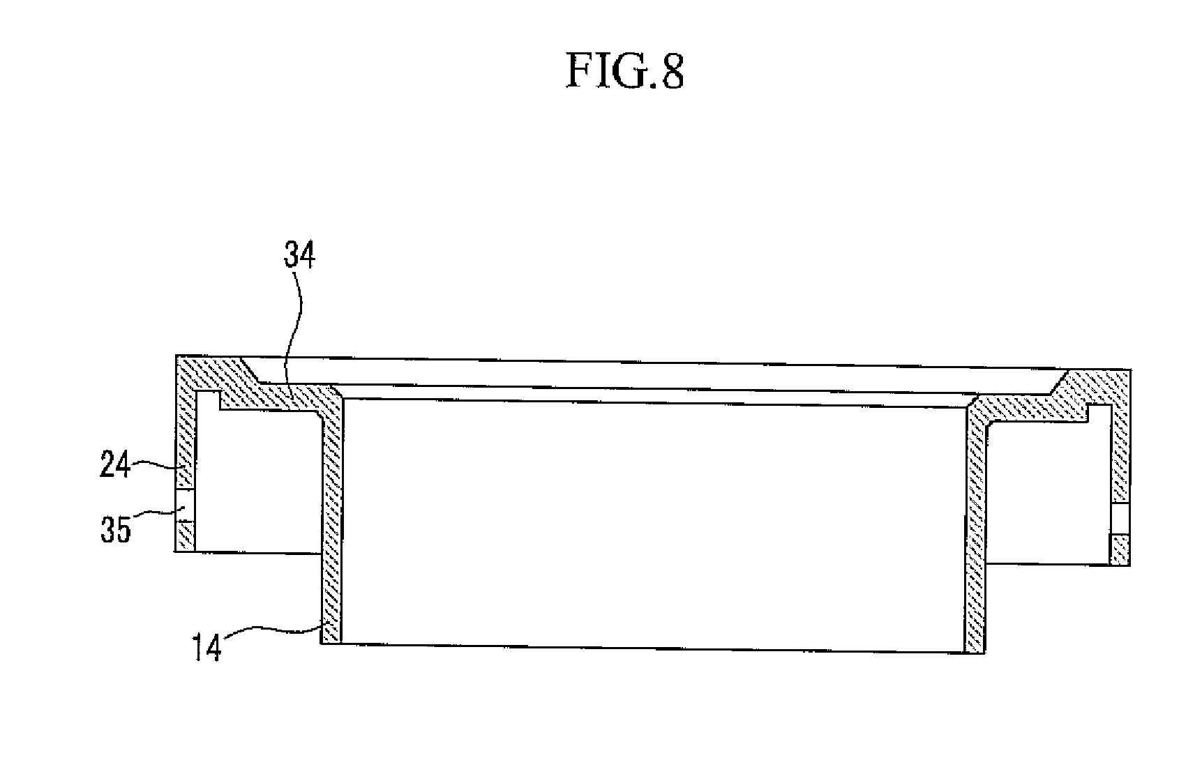
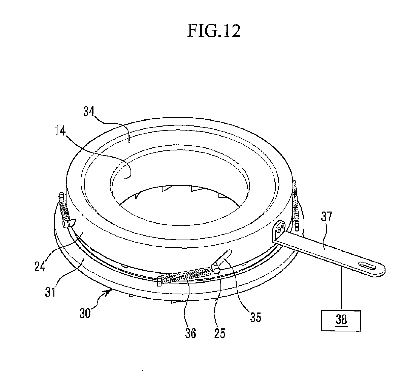
[0026] The control member may further include a third guide groove formed on an inner surface of the control member while being linked with the second guide groove. The actuator may further include a fixing key of which one end is fixed to the ring valve by penetrating the slant sliding hole and the other end is received in the third guide groove.
[0027] In the diffuser frame, a plurality of vein holes which the vein shaft penetrates may be formed in a direction parallel to the rotation shaft and the slant sliding hole may be spaced apart from the vein hole between two adjacent vein holes. The control member may be connected with a control unit sensing an operational condition of the gas compressor to be operated by a command from the control unit.
[0028] On the contrary, the actuator may include: i) a first actuator coupled with the plurality of vein shafts to control the rotational angles of the veins; and ii) a second actuator coupled with the ring valve to control the movement of the ring valve. The first actuator may include: i) a link member fixed to the vein shaft; ii) a guide shaft fixed to the link member with a distance from the vein shaft; and iii) a control member rotating the vein shaft by moving the guide shaft while forming a first guide groove receiving the guide shaft on one surface thereof.
[0029] The first guide groove may be formed in the radial direction of the impeller, and the control member may further include a second guide groove formed in a circumferential direction of the control member while being linked with the first guide groove.
[0030] The ring valve may have an extension ring on an outer surface thereof, and the actuator may include: i) a first nozzle spraying compressed air to one surface of the extension ring toward the diffuser passage; and ii) a second nozzle spraying compressed air to one opposite surface of the extension ring which is faraway from the diffuser passage.
[0031] The gas compressor may further include a top cover installed between the diffuser frame and the ring valve. The first nozzle may be formed throughout the top cover and the diffuser frame and the second nozzle is formed on the top cover. The control member, and the first and second nozzles may be connected with the control unit sensing the operational condition of the gas compressor to be operated by the command from the control unit.
[0032] Yet another exemplary embodiment of the present invention provides a method for controlling a flow rate of a gas compressor, including; i) sealing a diffuser passage by closing a ring valve in initial operation and reducing an area of the diffuser passage outside the ring valve by closing a plurality of veins; ii) opening the diffuser passage by opening the ring valve for rated operation; and iii) increasing the area of the diffuser passage outside the ring valve by opening the plurality of veins.
[0033] The method may further include; for stopping the operation after the increasing of the area of the diffuser passage, i) reducing the area of the diffuser passage outside the ring valve by closing the plurality of veins; and ii) sealing the diffuser passage by closing the ring valve.
BRIEF DESCRIPTION OF THE DRAWINGS
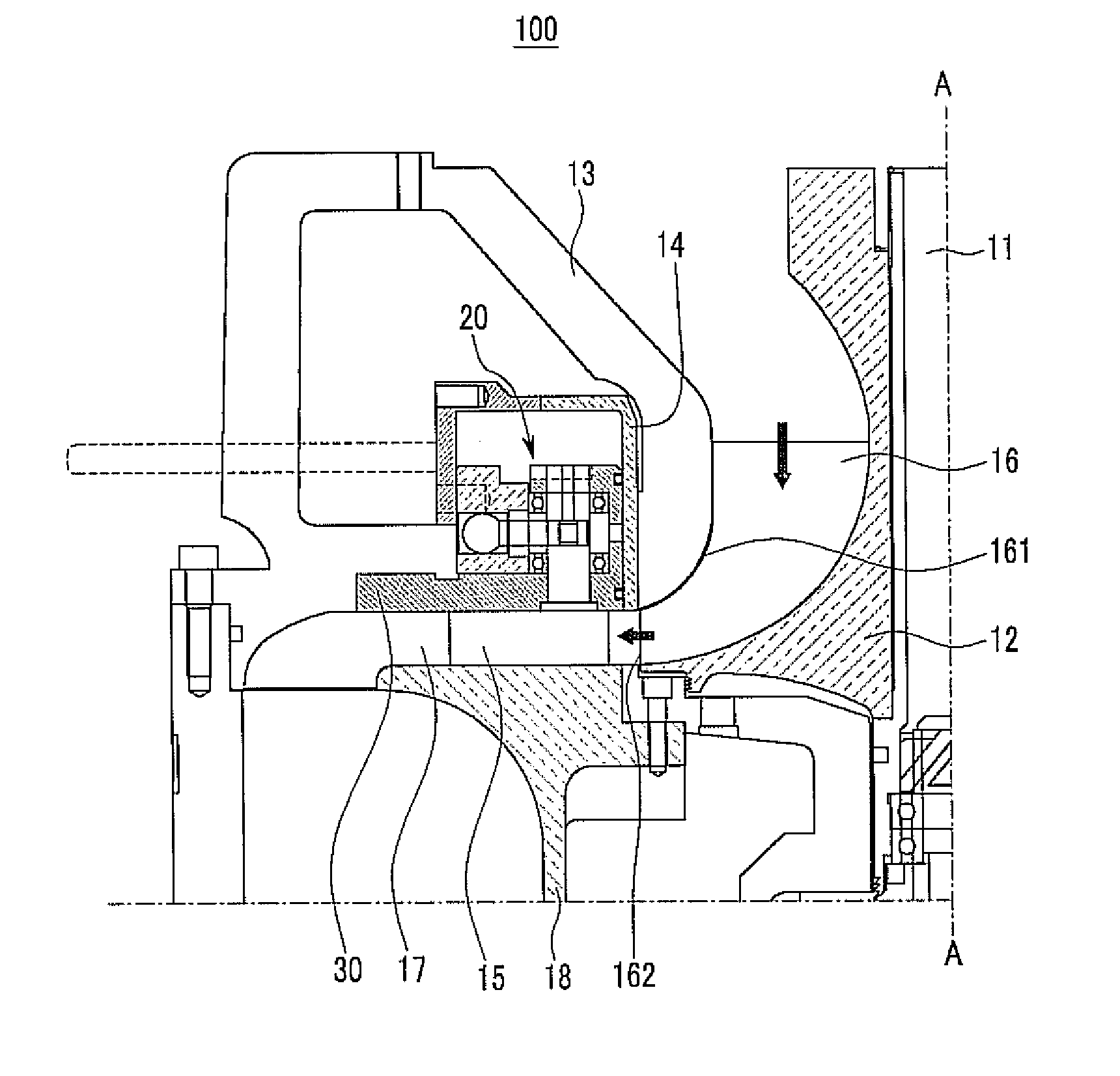
[0034] FIG. 1 is a partial cross-sectional view of a gas compressor according to a first exemplary embodiment of the present invention.
[0035] FIG. 2 is a partially enlarged diagram of the gas compressor shown in
[0036] FIG. 1.
[0037] FIG. 3 is a plan view schematically showing an impeller and a ring valve in the gas compressor shown in FIG. 1.
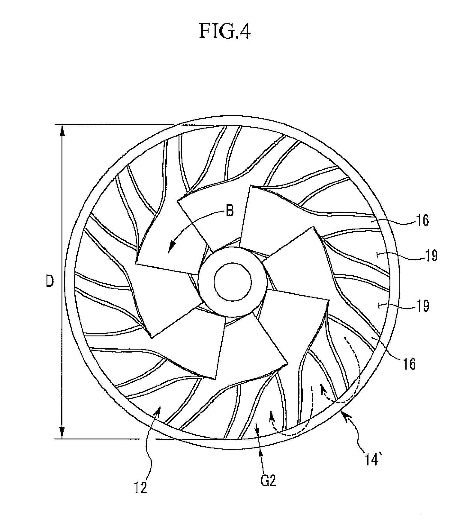
[0038] FIG. 4 is a plan view schematically showing an impeller and a ring valve in a gas compressor according to a comparative example.
[0039] FIG. 5 is a graph showing measurement of a vibration state depending on variation of a gap between a ring valve and the end of an impeller.
[0040] FIGS. 6 and 7 are exploded perspective views of a variable diffuser system in the gas compressor shown in FIG. 1.
[0041] FIG. 8 is a cross-sectional view of an outer guide ring, a ring valve, and a connector in the variable diffuser system shown in FIG. 7.
[0042] FIG. 9 is a perspective view of a combined state of the variable diffuser system in the gas compressor shown in FIG. 1.
[0043] FIGS. 10 to 13 are schematic diagrams of a variable diffuser system shown to describe a method for controlling a flow rate in the gas compressor according to the first exemplary embodiment of the present invention.
[0044] FIG. 14 is a partial cross-sectional view of a gas compressor according to a second exemplary embodiment of the present invention.
[0045] FIG. 15 is a partially enlarged diagram of the gas compressor shown in FIG. 14.
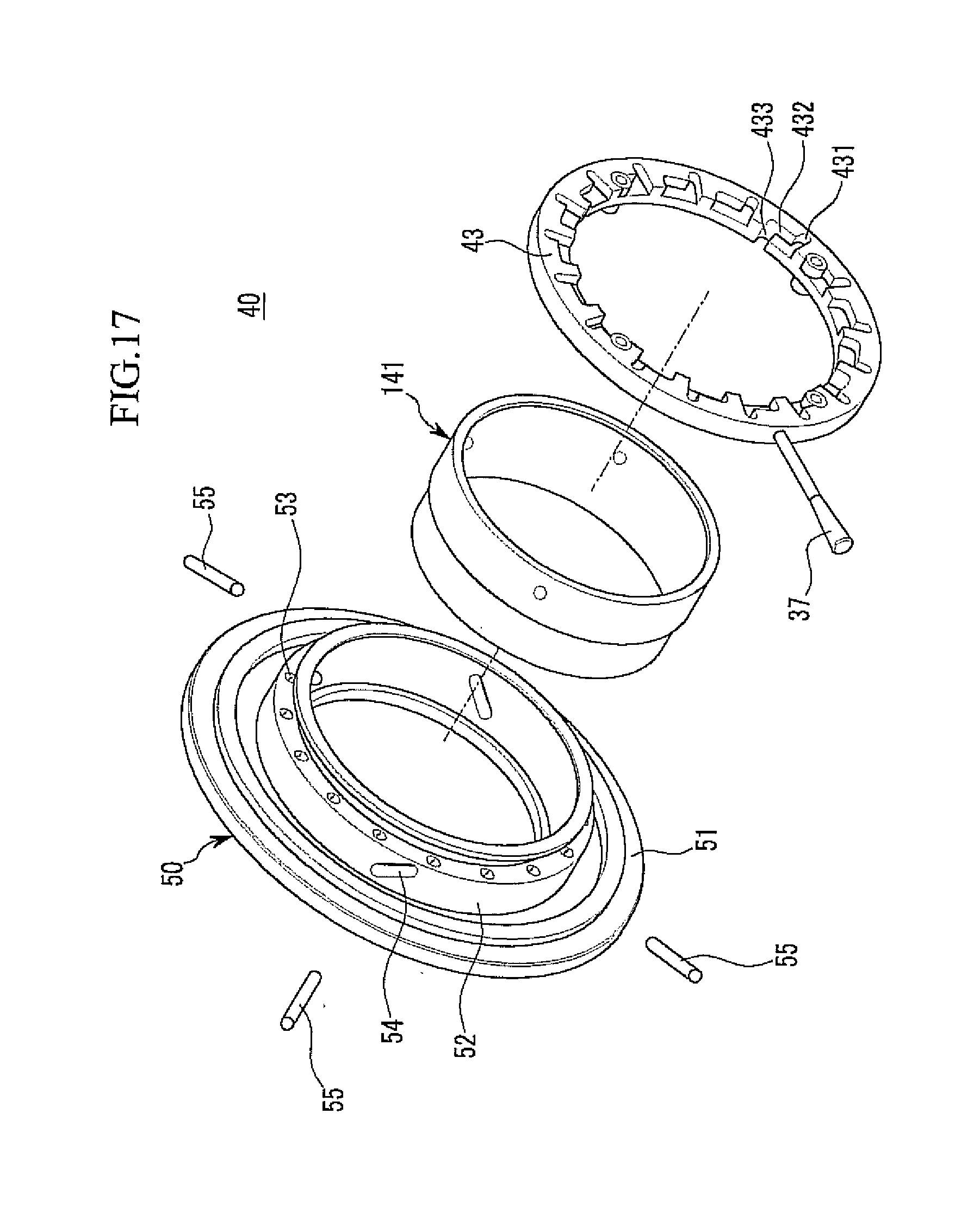
[0046] FIG. 16 is an exploded perspective view of a variable diffuser system in the gas compressor shown in FIG. 14.
[0047] FIG. 17 is a partially enlarged diagram of FIG. 16.
[0048] FIG. 18 is a perspective view showing a combined state of a diffuser frame and a ring valve shown in FIG. 17.
[0049] FIG. 19 is a right side view of the variable diffuser system in the gas compressor shown in FIG. 14.
[0050] FIG. 20 is a partially enlarged perspective view showing a part of a control member, and a guide shaft and a fixation key in a configuration of the variable diffuser system shown in FIG. 19.
[0051] FIGS. 21 to 23 are perspective views showing states of a ring valve and a vein at points (a), (b), and (c) shown in FIG. 19, respectively.
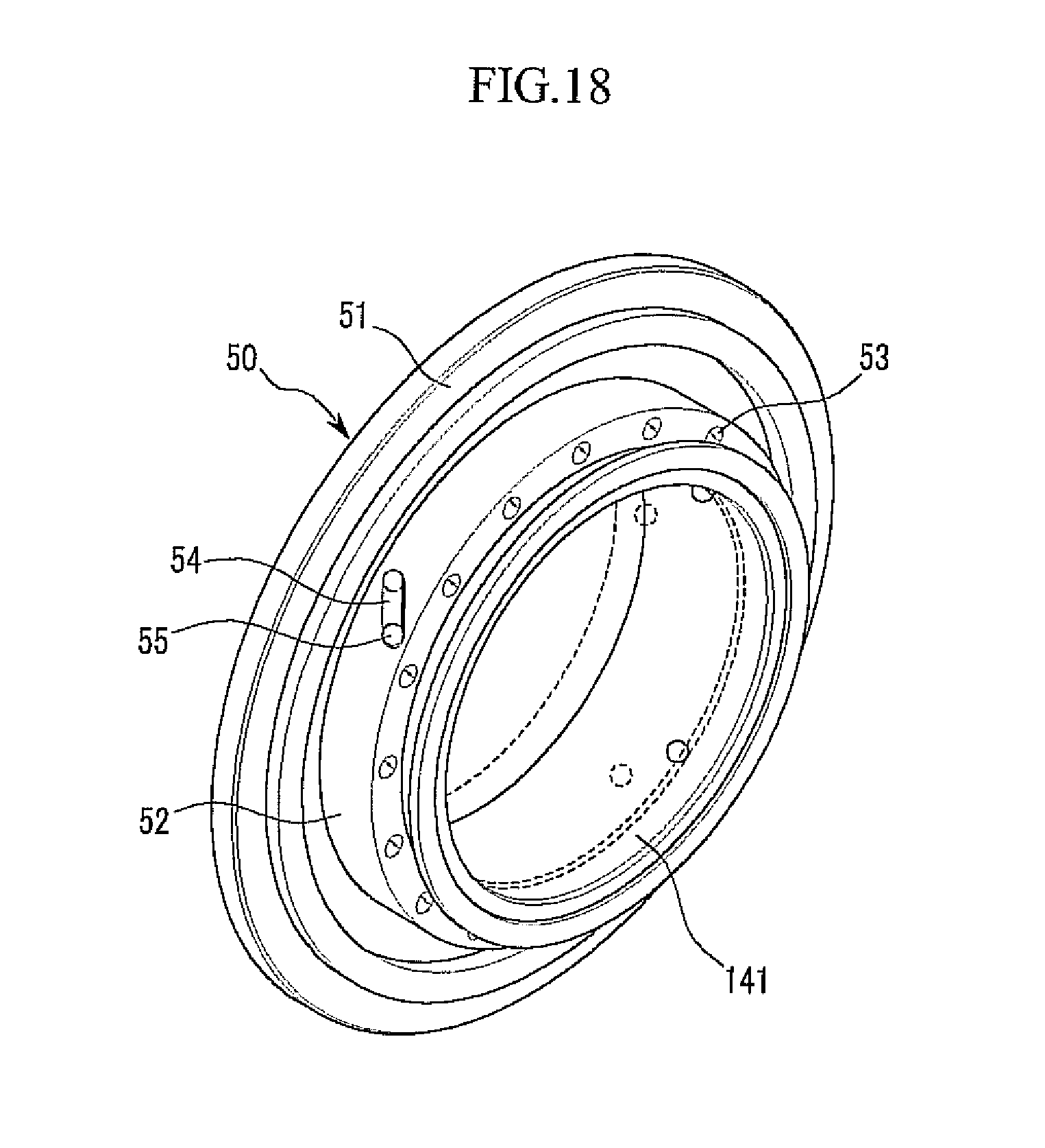
[0052] FIG. 24 is a partial cross-sectional view of a gas compressor according to a third exemplary embodiment of the present invention.
[0053] FIG. 25 is an exploded perspective view of a variable diffuser system in the gas compressor shown in FIG. 24.
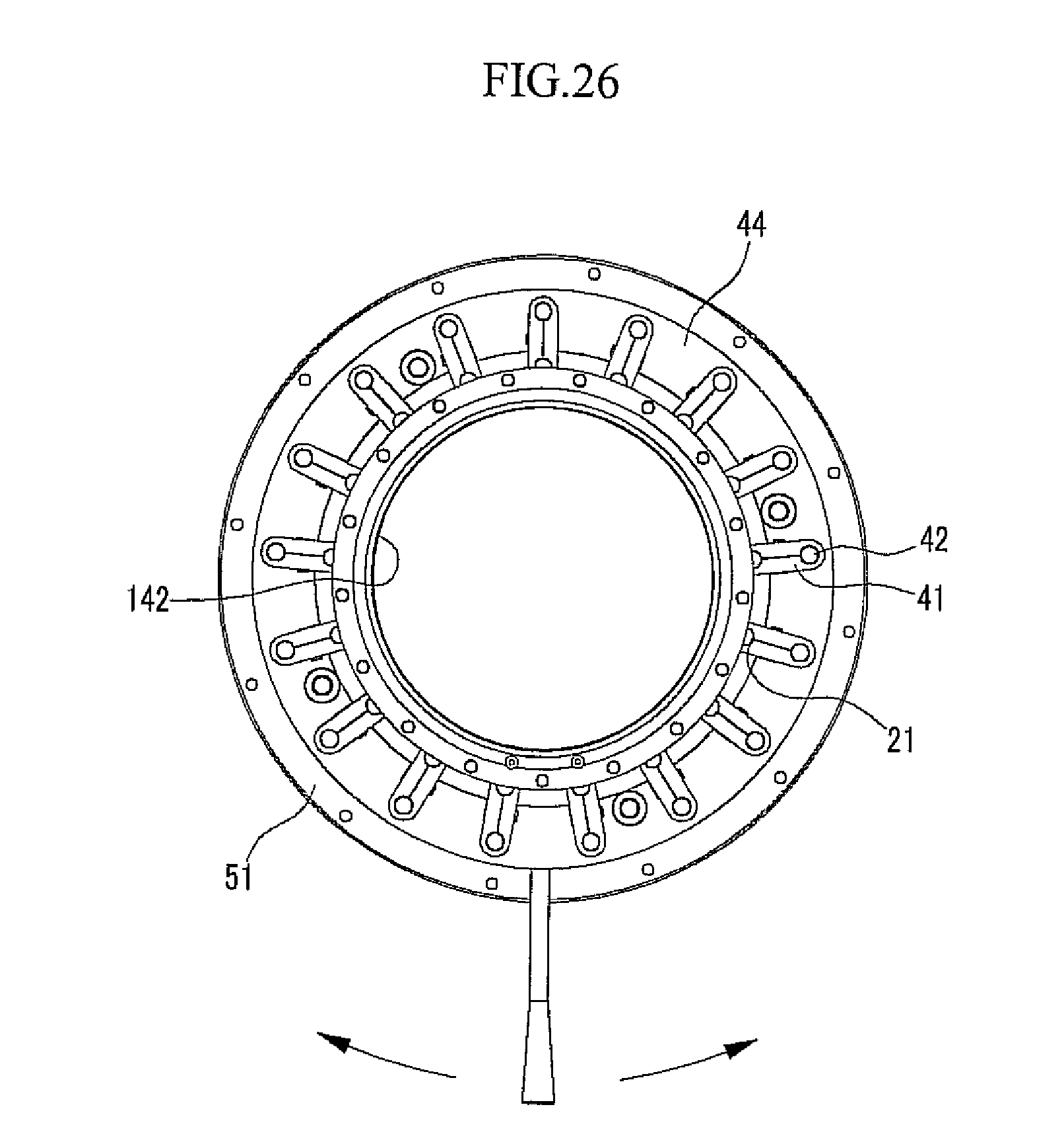
[0054] FIG. 26 is a right side view of the variable diffuser system shown in FIG. 24.
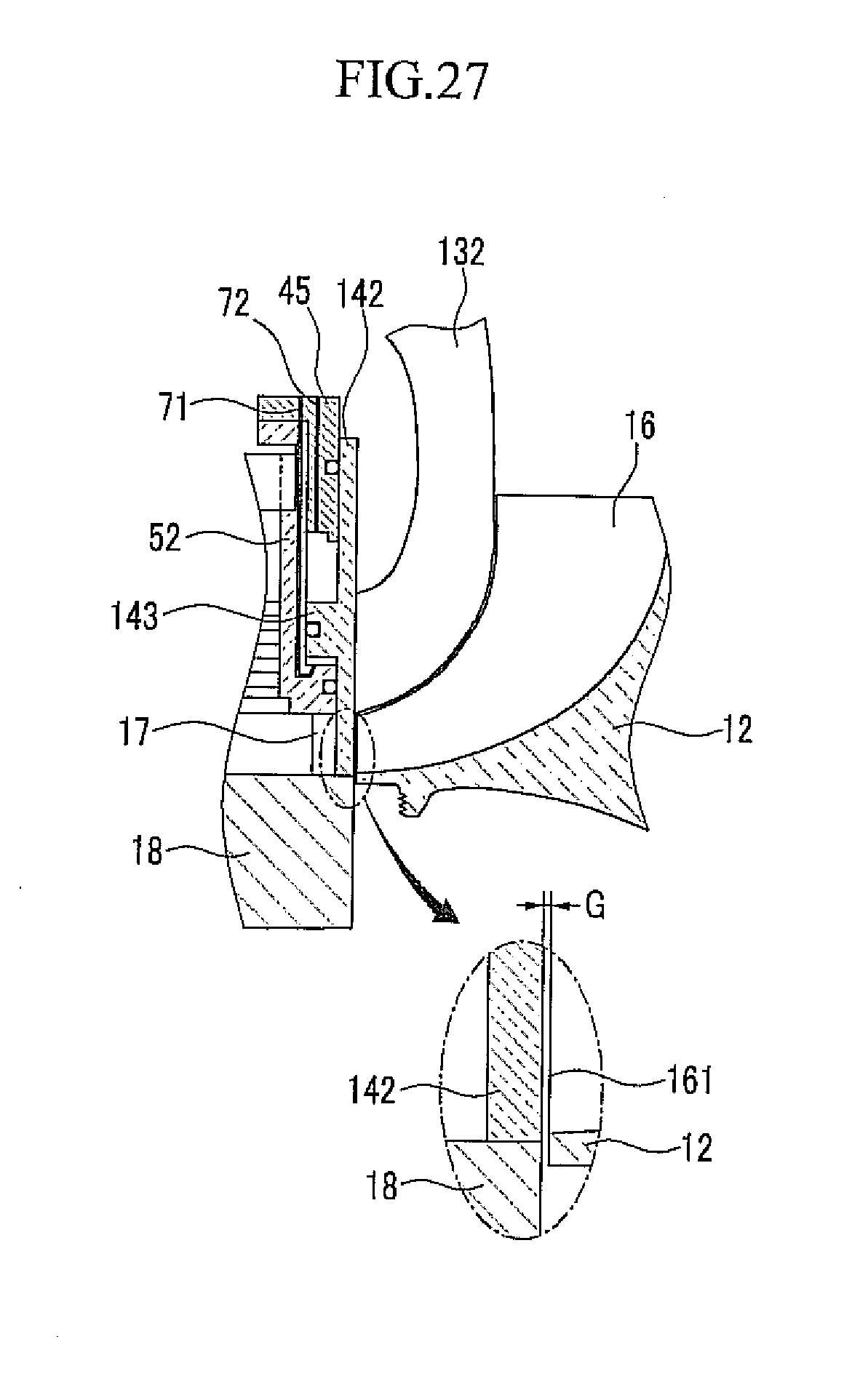
[0055] FIG. 27 is a partially enlarged diagram of the gas compressor shown in FIG. 24.
DETAILED DESCRIPTION OF THE EMBODIMENTS
[0056] The present invention will be described more fully hereinafter with reference to the accompanying drawings, in which exemplary embodiments of the invention are shown. As those skilled in the art would realize, the described embodiments may be modified in various different ways, all without departing from the spirit or scope of the present invention.
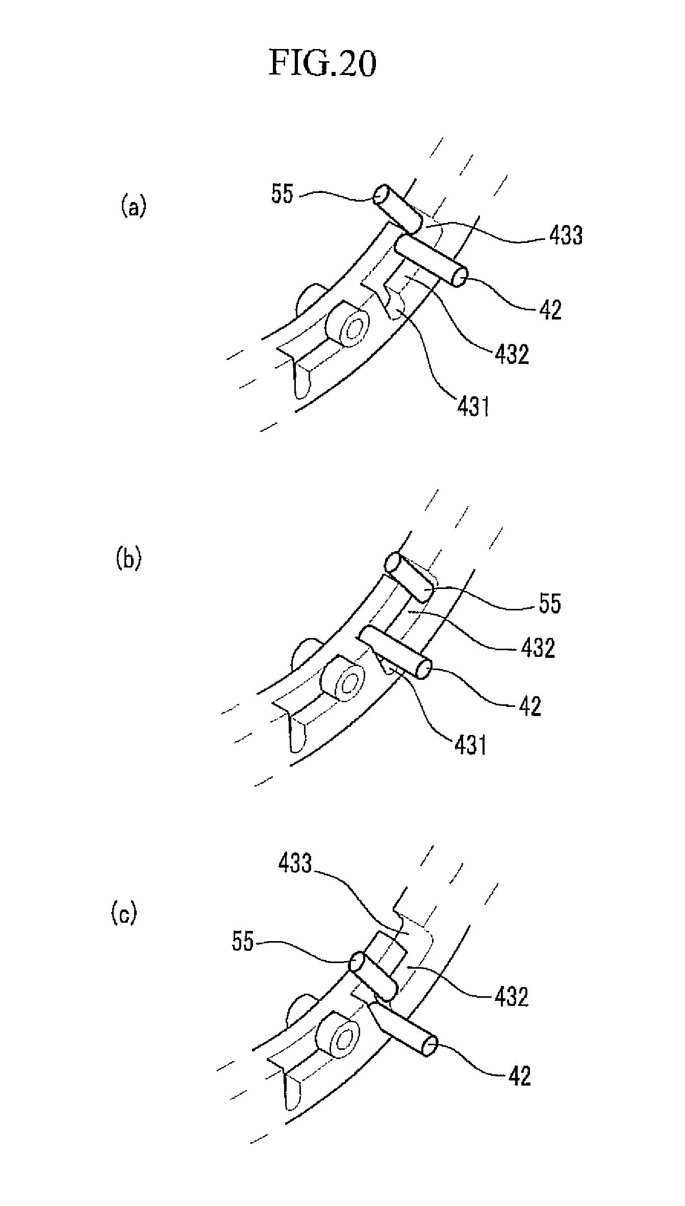
[0057] FIG. 1 is a partial cross-sectional view of a gas compressor 100 according to a first exemplary embodiment of the present invention.
[0058] Referring to FIG. 1, the gas compressor 100 of the first exemplary embodiment includes a rotation shaft 11, an impeller 12, a shroud 13, a ring valve 14, a plurality of veins 15 (one vein is shown in FIG. 1), and an actuator 20. The gas compressor 100 shown in FIG. 1 has bilateral symmetry around a center line (A-A line) of the rotation shaft 11.
[0059] The impeller 12 is fixed to the rotation shaft 11 and the rotation shaft 11 is coupled to a rotation shaft of a motor (not shown). A plurality of blades 16 having a curved radial pattern are formed on an external circumferential surface of the impeller 12. The blade 16 includes a wing surface 161 formed at a predetermined curvature and an edge surface 162 connected to the wing surface 161 and parallel to the rotation shaft 11. The shroud 13 is installed to surround the impeller 12 at a predetermined gap from the wing surface 161 of the blade 16.
[0060] When a motor operates to rotate the impeller 12, external gas flows into the rotating impeller 12 and is accelerated and compressed while passing through spaces among the blades 16 and thereafter, the external gas is discharged outside the edge surfaces 162 of the blades 16. In FIG. 1, a flow-in direction and a discharge direction of gas are indicated by arrows. In the exemplary embodiment, an outlet of the impeller represents a vicinity of the end of the impeller 12 where the compressed gas is discharged.
[0061] A diffuser passage 17 is positioned outside the outlet of the impeller 12. The diffuser passage 17 as a space formed between a discharge scroll 18 and a diffuser frame 30 is provided to have a ring shape having a predetermined height and a predetermined width. The diffuser passage 17 is connected with an internal passage of the discharge scroll 18 and converts kinetic energy into pressure energy of gas by diffusing and decelerating the high-speed and high-pressure gas discharged from the impeller 12.
[0062] In the exemplary embodiment, the ring valve 14, the plurality of veins 15, and the actuator 20 constitute a variable diffuser system. The ring valve 14 operates to open and close the diffuser passage 17 and prevents stall and surge by sealing the diffuser passage 17 at initial operation. The plurality of veins 15 operate to vary a rotational angle and stabilizes an air current by varying an area of the diffuser passage 17 outside the ring valve 14. The actuator 20 is mechanically coupled with the ring valve 14 and the plurality of veins 15 to sequentially control the movement of the ring valve 14 and the rotational angle of the vein 15.
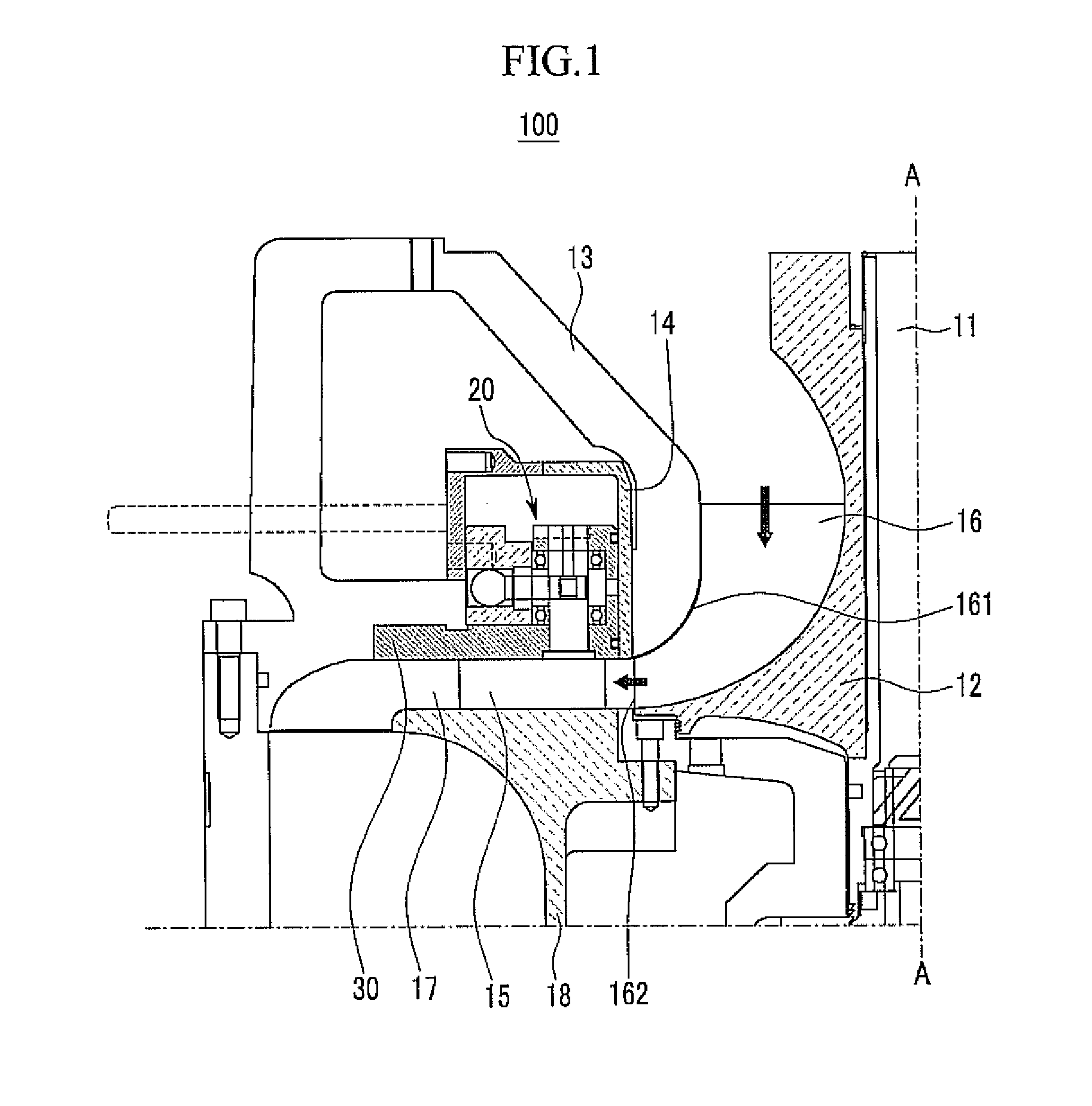
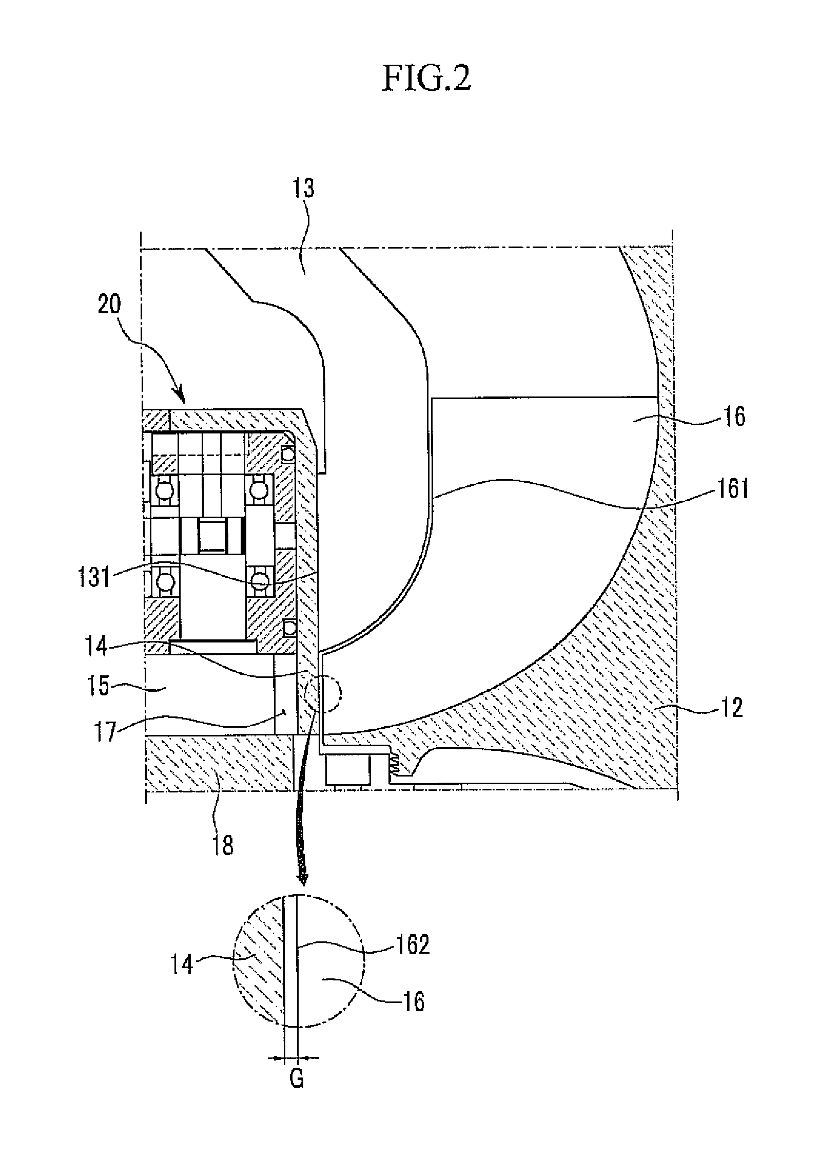
[0063] FIG. 2 is a partially enlarged diagram of the gas compressor 100 shown in FIG. 1 and shows a state in which the ring valve 14 descends toward the discharge scroll 18 to seal the diffuser passage 17. FIG. 3 is a plan view schematically showing the impeller 12 and the ring valve 14 in the gas compressor 100 shown in FIG. 1.
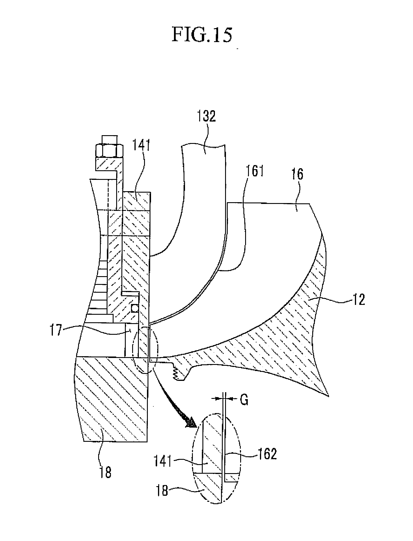
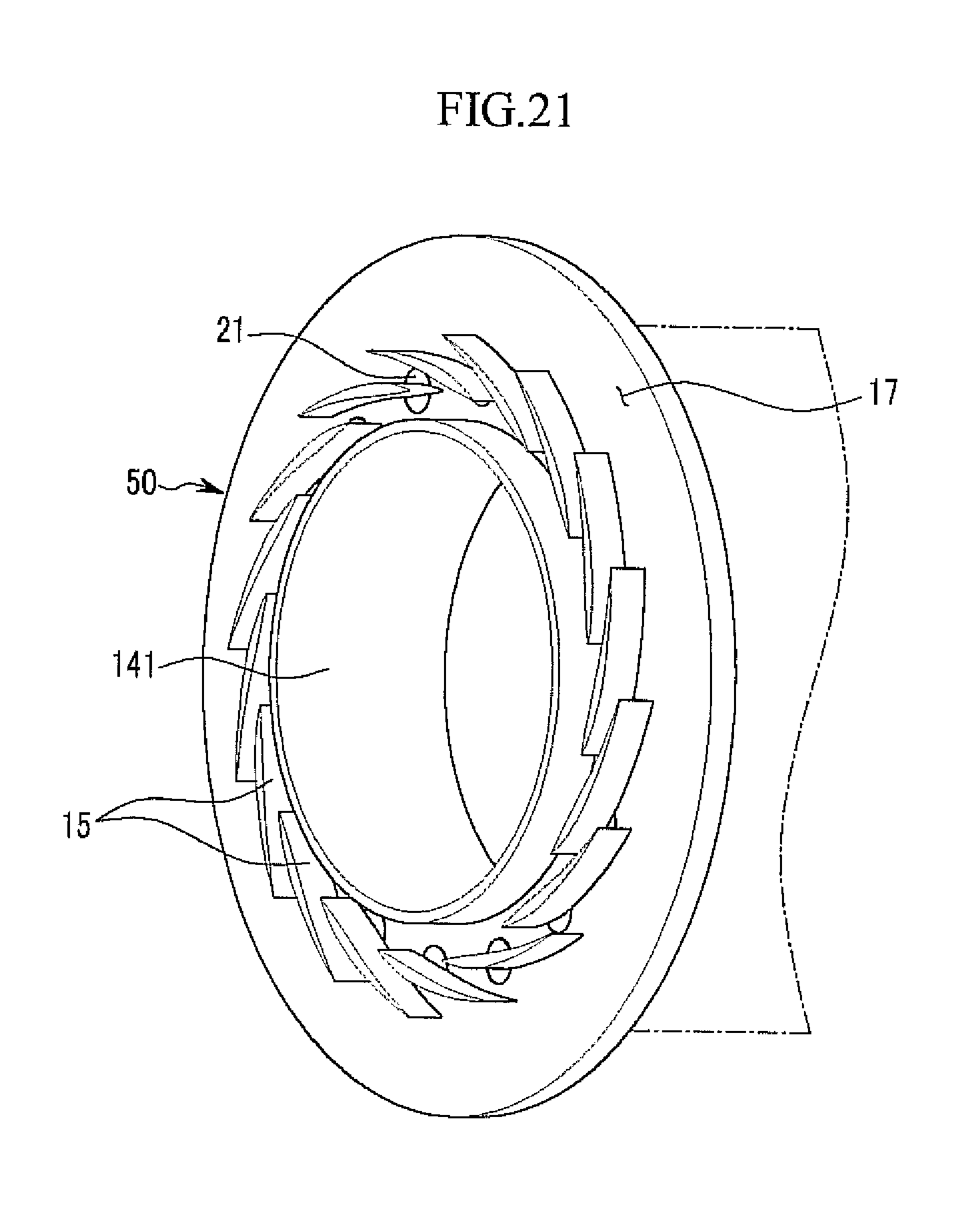
[0064] Referring to FIGS. 2 and 3, an outer wall 131 of the shroud 13 is parallel to the edge surface 162 of the blade 16 and maintains a predetermined gap from the edge surface 162 and the end of the impeller 12 in a radial direction of the impeller 12. Herein, the `radial direction` represents a direction rambling over in a direction perpendicular to the rotation shaft 11 from the center of the impeller 12.
[0065] The ring valve 14 contacts the outer wall of the shroud 13 and slides on the outer wall 131 of the shroud 13 to open or close the diffuser passage 17. Therefore, when the ring valve 14 descends toward the discharge scroll 18 to seal the diffuser passage 17, the ring valve 14 maintains the predetermined gap from the edge surface 162 and the end of the impeller 12.
[0066] In the exemplary embodiment, the gap G (see an enlarged circle of FIG. 2, and FIG. 3) between the ring valve 14 and the end of the impeller 12 measured in the radial direction of the impeller 12 is set to meet the following condition according to a diameter D (mm) (see FIG. 3) at the outlet of the impeller 12.
0.002D.ltoreq.G.ltoreq.0.0080D (1)
[0067] A minimum value of the gap G is set by considering limitations such as thermal expansion of the impeller 12 and the ring valve 14 and a radial clearance of the rotation shaft 11. That is, when the gap G is less than 0.002 D, the impeller 12 and the ring valve 14 may contact each other by the thermal expansion of the impeller 12 and the ring valve 14 and it is difficult to precisely adjust the clearance between the rotation shaft 11 and the impeller 12 during installation. Further, when assembly precision is low, the impeller 12 may hit the ring valve 14 while the gas compressor 100 operates.
[0068] A maximum value of the gap G is set by considering functionality of the ring valve 14 preventing the stall and the surge. That is, when the gap G is more than 0.008 D, gas flows backwards through a space between the impeller 12 and the ring valve 14 to cause the stall and the surge, and as a result, stability and efficiency of the gas compressor 100 deteriorates significantly. The gas compressor 100 of the first exemplary embodiment may implement high efficiency as the gap G between the ring valve 14 and the end of the impeller 12 is set to be closer to the minimum value in the range of Condition (1).
[0069] The diameter D at the outlet of the impeller 12 may be in the range of 10 to 800 mm and in this case, the gap G between the ring valve 14 and the end of the impeller 12 may be set to the range of 0.02 to 6.4 mm according to Condition (1). When the gas compressor 100 is a high-speed gas compressor of 7,000 rpm or more, although the gap G may vary depending on rated air volume and pressure, the gap G may be 0.2 mm if the diameter D at the outlet of the impeller 12 is 50 mm and the gap G may be 2 mm if the diameter D at the outlet of the impeller 12 is 500 mm.
[0070] FIG. 4 is a plan view schematically showing an impeller 12 and a ring valve 14' in a gas compressor according to a comparative example in which a gap G2 between the ring valve 14' and the end of the impeller 12 is more than 0.008 D. Referring to FIGS. 3 and 4, the reason why a difference in stability and efficiency is generated between the gas compressor of the exemplary embodiment that meets Condition (1) and the gas compressor of the comparative example that does not meet Condition (1) will be described. In FIGS. 3 and 4, arrow B represents a rotational direction of the impeller 12.
[0071] First, referring to FIG. 3, in the gas compressor 100 of the exemplary embodiment, the ring valve 14 maintains the gap G that meets Condition (1) from the end of the impeller 12 on the circumference of the impeller 12. For example, when the diameter D at the outlet of the impeller 12 is 200 mm, the gap G is set to the range of 0.4 to 1.6 mm.
[0072] In the gas compressor 100 of the exemplary embodiment, when the ring valve 14 descends to seal the diffuser passage 17, the impeller 12 is completely surrounded by the shroud 13 and the ring valve 14 except for an inlet into which external gas flows. When initial operation starts in this state, gas compressed in spaces 19 among the blades 16 cannot be discharged outside the impeller 12 and just continuously rotates in the same space while the gas cannot flow backwards against the impeller 12 due to centrifugal force.
[0073] In FIG. 3, a rotational direction of the compressed gas is indicated by a dotted arrow. Therefore, the entirety of the spaces 19 among the blades 16 is filled with the compressed gas and external gas cannot be suctioned at the inlet of the impeller 12 any more.
[0074] As a result, while gas is not additionally suctioned other than a minimum amount of gas suctioned at initial operation, since a rotation speed of the gas compressor increases up to a rated rotation speed, no-load operation can be implemented and the stall and surge caused due to the backflow of gas can be prevented. Further, even in the case where gas flows backwards to the impeller 12 due to a problem in a used place connected with the discharge scroll 18, the backflow of gas can be prevented by sealing the diffuser passage 17 with the ring valve 14, thereby effectively suppressing the stall and the surge.
[0075] Referring to FIG. 4, in the gas compressor of the comparative example, the ring valve 14' maintains the gap G2 that does not meet Condition (1) from the end of the impeller 12 on the circumference of the impeller 12. For example, when the diameter D at the outlet of the impeller 12 is 200 mm, the gap G2 is more than 1.6 mm.
[0076] In the case of the comparative example, gas flows backwards through a space between the impeller 12 and the ring valve 14'. That is, compressed gas in the spaces 19 among the blades 16 when the impeller 12 rotates flows backwards to spaces among other blades in a direction opposite to a rotation direction of the impeller 12 through a space between the impeller 12 and the ring valve 14' to flows toward the inlet of the impeller 12. In FIG. 4, a flow direction of the compressed gas is indicated by an arrow. Therefore, in the gas compressor of the comparative example, no-load operation cannot be implemented, and the stall and surge caused due to the backflow of gas are permitted.
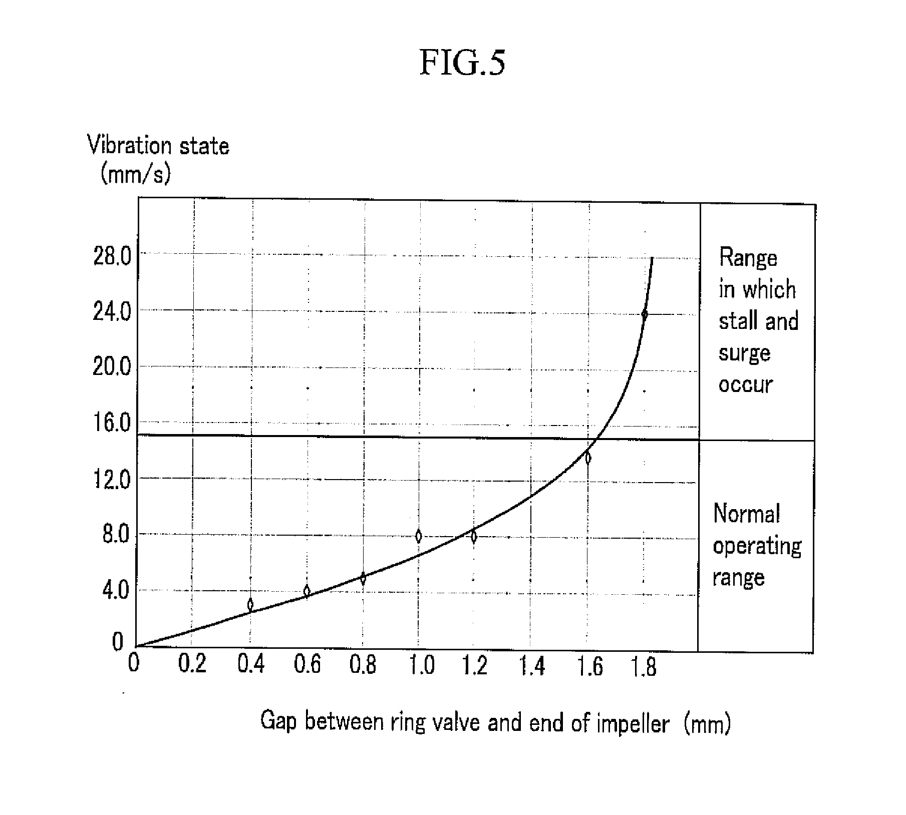
[0077] FIG. 5 is a graph showing measurement of a vibration state depending on variation of a gap G between a ring valve and the end of an impeller. In the gas compressor used in an experiment, the diameter D at the outlet of the impeller is 200 mm, the height of the blade is 18 mm, and the experiment is performed under room temperature and atmospheric pressure conditions. The gap G between the ring valve and the end of the impeller is 0.4 mm or more according to Condition (1) and a vibration value of the impeller is measured while extending the gap by each 0.2 mm.
[0078] Referring to FIG. 5, as the gap G between the ring valve and the end of the impeller increases, the vibration value gradually increases, but a range in which the gap G is equal to or less than 1.6 mm belongs to a normal operation range. On the contrary, it can be verified that the vibration value increase rapidly while the gap G is more than 1.6 mm to enter an initial stall and surge region. From the result of FIG. 5, stability and efficiency are significantly deteriorated in the gas compressor of the comparative example that does not meet Condition 1.
[0079] In the gas compressor 100 of the first exemplary embodiment, the ring valve 14 basically has a flow rate control function and more primarily serves as a valve that closes the entire outlet of the impeller 12 so that the compressed gas cannot deviate from the impeller 12. Therefore, the backflow of gas is prevented by using the ring valve 14 to effectively prevent the stall and the surge.
[0080] The actuator 20 is mechanically coupled with the ring valve 14 and the plurality of veins 15 and sequentially control the movement of the ring valve 14 and the rotational angle of the vein 15. Next, a coupling structure of the ring valve 14, the plurality of veins 15, and the actuator 20 will be described.
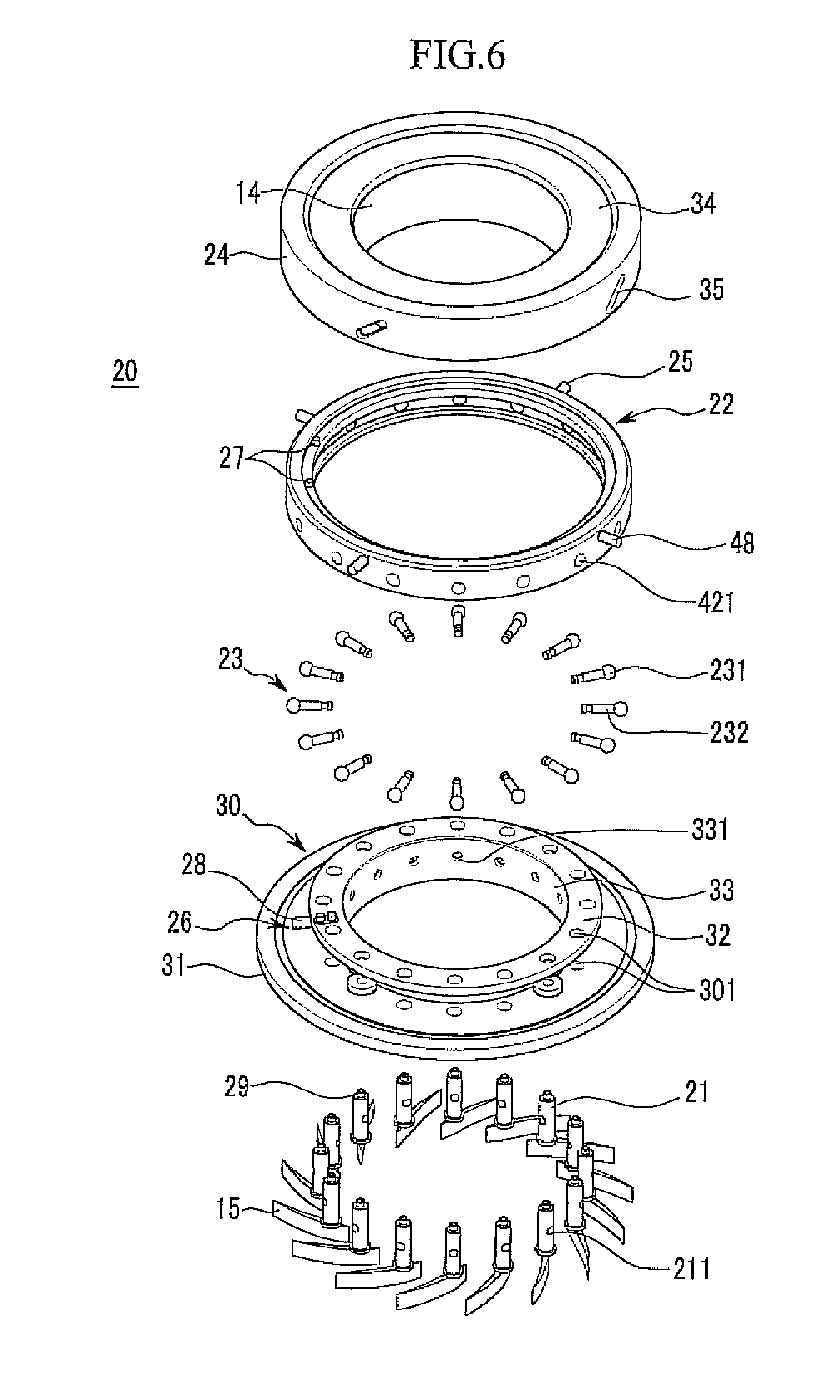
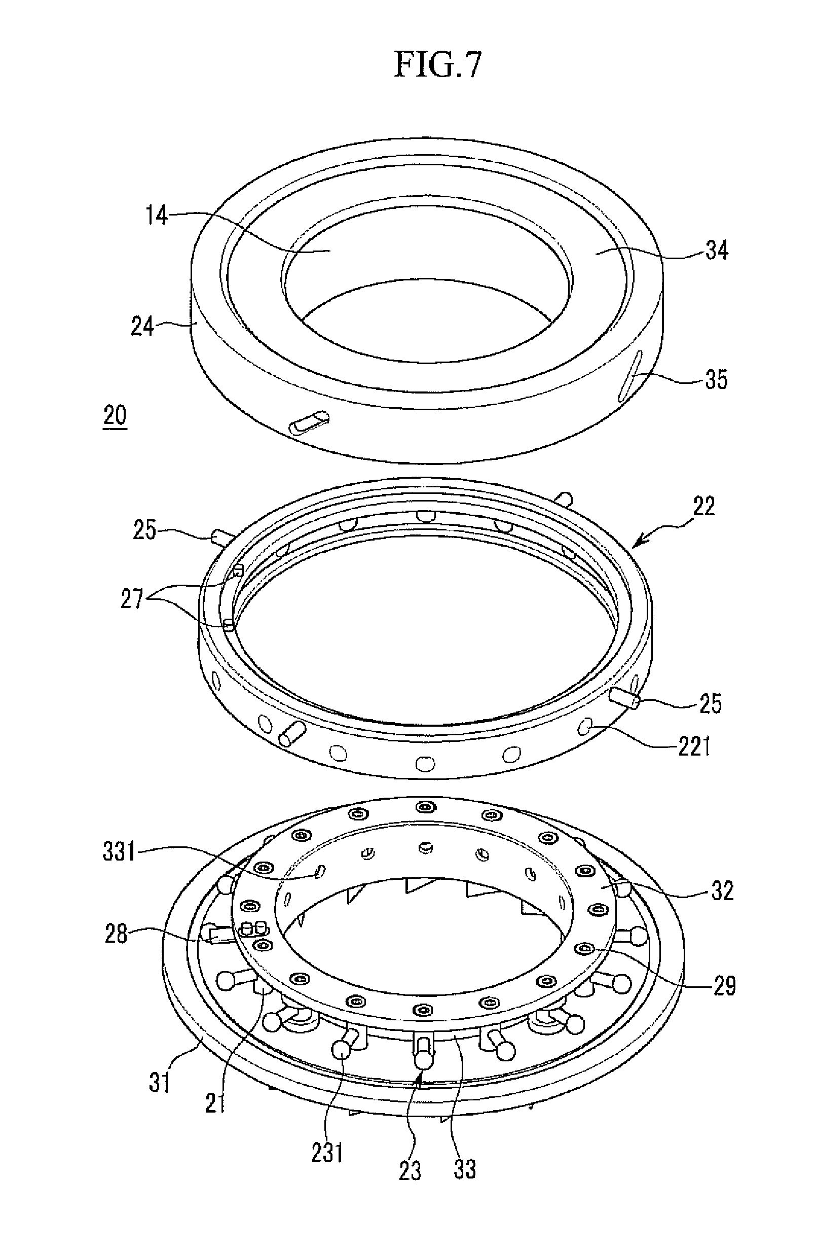
[0081] FIGS. 6 and 7 are exploded perspective views of a variable diffuser system in the gas compressor 100 shown in FIG. 1.
[0082] Referring to FIGS. 6 and 7, the plurality of veins 15 are arranged at regular intervals in a circumferential direction of the diffuser passage 17 at one portion of the diffuser frame 30. A vein shaft 21 is fixed to each vein 15 and a cavity 211 penetrating the vein shaft 21 is formed on the vein shaft 21 in a radial direction.
[0083] The diffuser frame 30 includes a first flange 31 and a second flange that are spaced apart from each other, and a connection flange 33 connecting an inner end of the second flange 32 with an inner end of the first flange 31. A plurality of first openings 301 for mounting the vein shaft 21 are arranged in the first and second flanges 31 and 32 at regular intervals in a circumferential direction.
[0084] The actuator 20 includes an inner guide ring 22 surrounding the plurality of vein shafts 21, a plurality of ball levers 23 coupling the inner guide ring 22 with the vein shafts 21, an outer guide ring 24 integrally connected with the ring valve 14 while surrounding the inner guide ring 22, and a plurality of fixing pins 25 coupling the outer guide ring 24 with the inner guide ring 22.
[0085] A plurality of second openings 221 penetrating the inner guide ring 22 in the radial direction of the impeller 12 are arranged in the inner guide ring 22 at regular intervals in the circumferential direction. When the vein shaft 21 penetrates the first openings 301 of the diffuser frame 30 to be coupled to the diffuser frame 30, the inner guide ring 22 is placed outside the connection flange 33 and the second flange 32 to surround the plurality of vein shafts 21. In this case, the cavity 211 of the vein shaft 21 and the second openings 221 of the inner guide ring 22 are placed to face each other in the radial direction.
[0086] The ball lever 23 penetrates the second openings 221 of the inner guide ring 22 and the cavity 211 of the vein shaft 21 to be fixed to the vein shaft 21. The ball lever 23 includes a ball member 231 closely attached to a side wall of the second opening 221 of the inner guide ring 22 and a support member 232 inserted into the cavity 211 to be fixed to the vein shaft 21. Therefore, when the inner guide ring 22 rotates, the vein shaft 21 rotates together in link with the inner guide ring 22 through the ball lever 23.
[0087] A stop member 26 controlling a rotational speed of the inner guide ring 22 is installed in the diffuser frame 30 and the inner guide ring 22. The stop member 26 includes a pair of first bars 27 positioned on one surface of the inner guide ring 22 with a distance from each other in the circumferential direction and a second bar 28 fixed to the diffuser frame 30 and protruding so that a portion thereof is positioned between the pair of first bars 27. The pair of first bars 27 are positioned spaced apart from each other by a maximum rotational distance of the inner guide ring 22 and the rotation of the inner guide ring 22 is limited while any one of the pair of first bars 27 is suspended to the second bar 28.
[0088] Meanwhile, an inner space into which a fixing screw 29 is inserted is formed in the vein shaft 21 to strongly fasten the ball lever 23 with the fixing screw 29. Further, a plurality of third openings 331 penetrating the connection flange 33 in the radial direction of the impeller 12 are formed in the connection flange 33. At the time of disassembling the variable diffuser system, the ball lever 23 is pushed out by pushing a tool into the third opening 331 from the inside of the connection flange 33 to thereby separate the ball lever 23 from the vein shaft 21.
[0089] The outer guide ring 24 is positioned in parallel to the ring valve 14 and is formed integrally with the ring valve 14 by a connector 34. FIG. 8 is a cross-sectional view of the outer guide ring 24, the ring valve 14, and the connector 34 in the variable diffuser system shown in FIG. 7. Referring to FIG. 8, the outer guide ring 24 is lower than the ring valve 14 and the connector 34 integrally connects the end of the ring valve 14 and the end of the outer guide ring 24.
[0090] Referring back to FIGS. 6 and 7, one or more slant sliding holes 35 are formed in the outer guide ring 24. As one example, four slant sliding holes 35 may be arranged in the circumferential direction of the outer guide ring 24. The fixing pins 25 are provided as many as the slant sliding holes 35 and each of the fixing pins 25 is fixed to the inner guide ring 22 through the slant sliding hole 35.
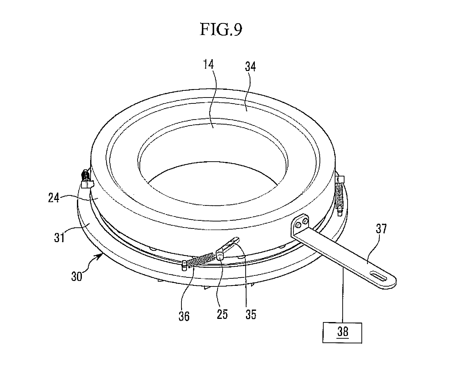
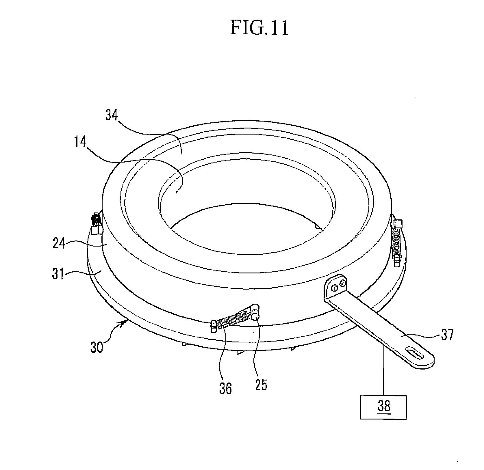
[0091] FIG. 9 is a perspective view of a combined state of the variable diffuser system in the gas compressor 100 shown in FIG. 1.
[0092] Referring to FIG. 9, an elastic member 36 is installed between the diffuser frame 30 and the fixing pin 25. One end of the elastic member 36 is fixed to the diffuser frame 30 and the opposite end of the elastic member 36 is fixed to the fixing pin 25. The elastic member 36 exerts force to pull the fixing pin 25 in a clockwise direction (based on the figure) by using restoration force.
[0093] In addition, a control handle 37 is attached to the outer guide ring 24 to control the rotation of the outer guide ring 24 by operating the control handle 37. The control handle 37 is connected with a control unit 38 that senses operational conditions of the gas compressor 100 such as a flow rate of gas passing through the impeller 12, a difference in pressure between the inlet and the outlet of the impeller 12, the backflow of gas caused due to a problem in a used place, and is operated by a command from the control unit 38.
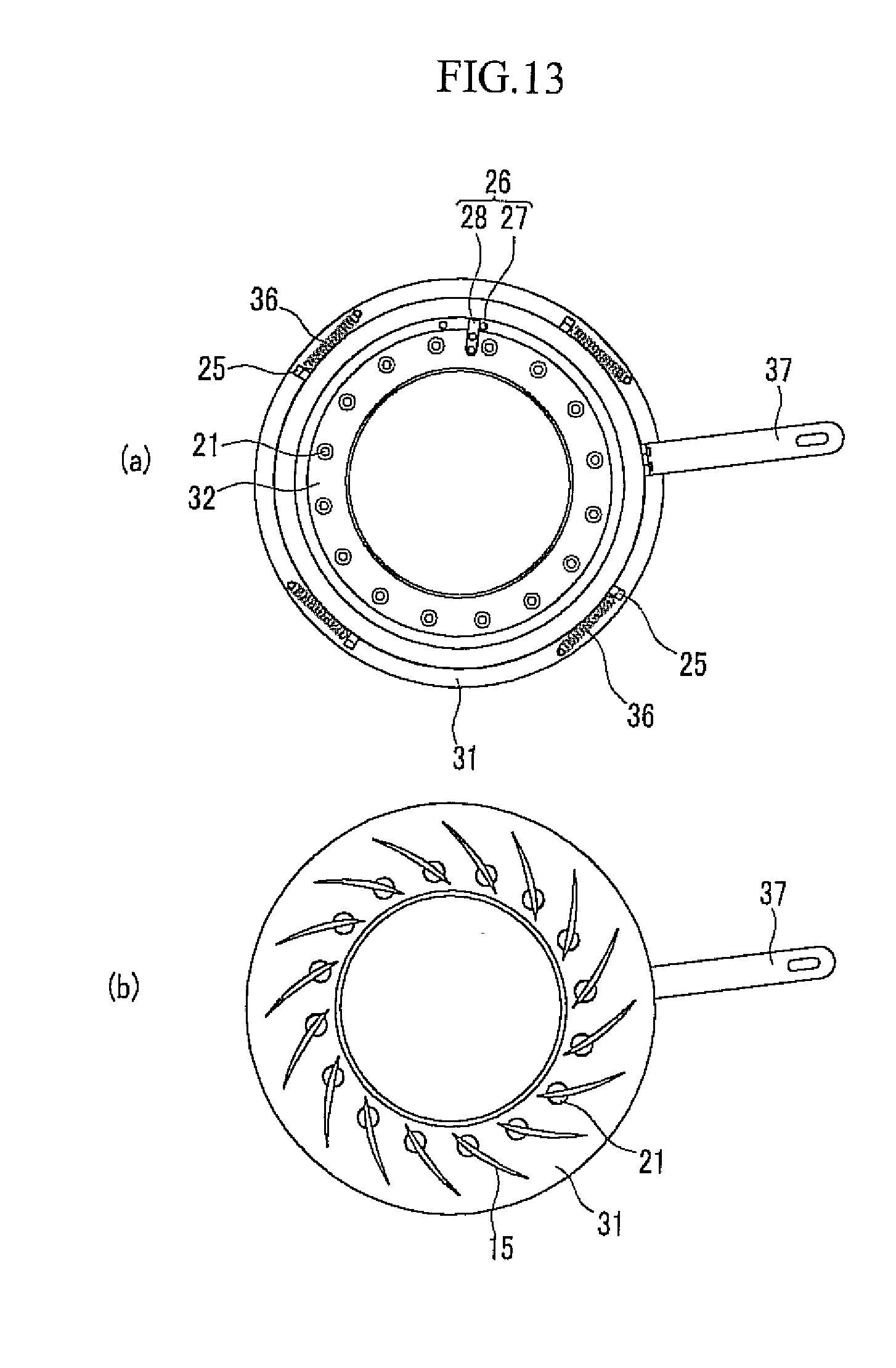
[0094] Referring to FIGS. 9 to 13, a method for controlling the flow rate of the gas compressor 100 using the variable diffuser system will be described. A `clockwise direction` and a `counterclockwise direction` to be described below are based on the figures.
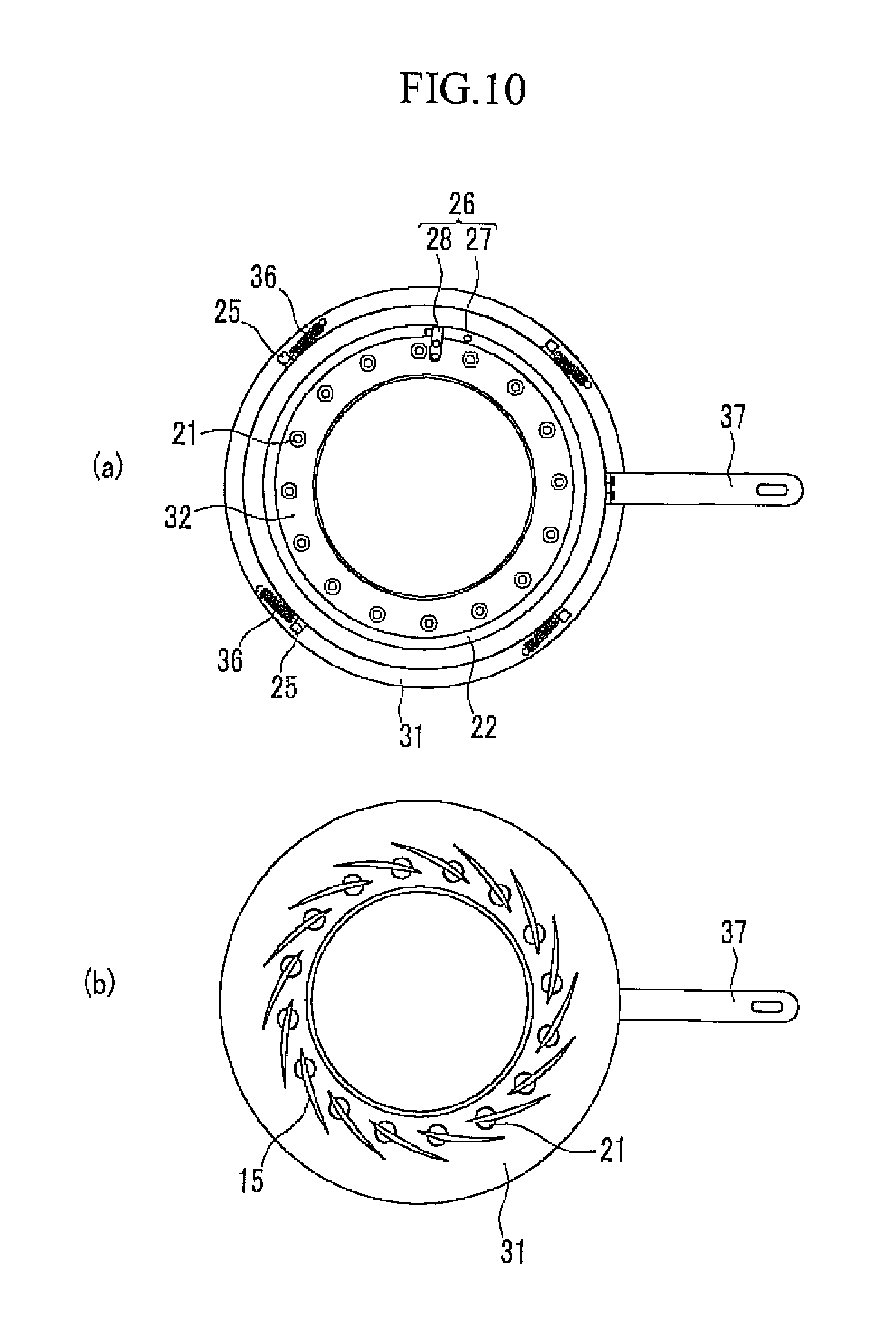
[0095] FIGS. 10 and 11 show states of the ring valve 14 and the vein 15 for initial operation. Referring to FIGS. 10 and 11, the outer guide ring 24 and the ring valve 14 descend in the initial operation, such that the ring valve 14 seals the diffuser passage 17. In addition, the plurality of veins 15 maintain a closed state to minimize an area of the diffuser passage 17 outside the ring valve 14 (step S1).
[0096] In this case, a fixing pin 25 is positioned at an upper end of a slant sliding hole 35. In addition, an elastic member 36 pulls the fixing pin 25 in the clockwise direction by using restoration force, but the inner guide ring 22 cannot be moved in the clockwise direction any longer by the stop member 26. Therefore, an angle of the vein 15 is limited at a designed minimum flow rate position.
[0097] As described above, when the operation of the gas compressor 100 starts with the diffuser passage 17 sealed with the ring valve 14, no-load operation can be implemented as described above with reference to FIG. 3. Further, the stall and the surge can be suppressed by preventing the backflow of the compressed gas.
[0098] Thereafter, the control handle 37 and the outer guide ring 24 are rotated in the counterclockwise direction for rated operation. Therefore, as shown in FIG. 9, the fixing pin 25 serves as a slant guide, such that the outer guide ring 24 ascends from the diffuser frame 30. Therefore, the ring valve 14 ascends to open the diffuser passage 17 (step S2).
[0099] In this case, since the elastic member 36 pulls the fixing pin 25 in the clockwise direction, the inner guide ring 22 and the vein 15 linked therewith maintain the minimum flow rate position without moving. In step S2, the fixing pin 25 is positioned at a lower end of the slant sliding hole 35.
[0100] Thereafter, the control handle 37 and the outer guide ring 24 are further rotated in the counterclockwise direction. Therefore, as shown in FIGS. 12 and 13, the outer guide ring 24 overcomes the restoration force of the elastic member 36 applied to the fixing pin 25 without variation in height, and pulls and rotates the fixing pin 25 in the counterclockwise direction. As a result, the vein 15 is opened while the fixing pin 25, and the inner guide ring 22 and the vein shaft 21 move to increase an area of the diffuser passage 17 (step S3). During this process, the fixing pin 25 moves until the rotation of the inner guide ring 22 is stopped by the stop member 26.
[0101] Next, an operational sequence for the stop is opposite to the above-mentioned process.
[0102] That is, in FIG. 12, when the control handle 37 rotates in the clockwise direction, the elastic member 36 pulls the fixing pin 25 in the clockwise direction, such that the fixing pin 25 cannot serve as the slant guide with respect to the outer guide ring 24. Therefore, the outer guide ring 24 may just rotate in the clockwise direction without variation in height and the fixing pin 25 pulled by the restoration force of the elastic member 36 moves in the clockwise direction to close the vein 15 (step S4, see FIG. 9). During this process, the fixing pin 25 moves until the rotation of the inner guide ring 22 is stopped by the stop member 26.
[0103] In addition, in FIG. 9, when the control handle 37 is further rotated in the clockwise direction, the fixing pin 25 serves as the slant guide, and as a result, the outer guide ring 24 and the ring valve 14 descend to seal the diffuser passage 17 as shown in FIG. 11 (step S5). Therefore, even for a period from the rated operation to the stopping of the impeller 12, the surge can be effectively suppressed.
[0104] As described above, in the gas compressor 100 of the exemplary embodiment, since the ring valve 14 and the plurality of veins 15 are together controlled by using a single actuator 20, a mechanical configuration for the control can be simplified. Further, in the gas compressor 100 of the exemplary embodiment, since the ring valve 14 and the vein 15 are sequentially driven, a flow rate range which can be controlled with the variable diffuser system may be extended to the maximum 100%. In the exemplary embodiment, a flow rate control range of the ring valve 14 is approximately in the range of 0 to 45% and a flow rate control range of the vein 15 is approximately in the range of 45 to 100%.
[0105] Meanwhile, in FIGS. 1 to 3, a structure in which spaces among blades 16 can be in communication with each other over a wing surface 161 inside a shroud 13 is shown, but a structure in which a cover plate (not shown) is fixed to the wing surface 161 to separate the spaces among the blades 16 from each other on the wing surface 161 can also be applied.
[0106] That is, in the case of the latter, the spaces among the blades 16 are separated by the cover plate except for an inlet of the impeller 12 into which gas flows and an outlet (an edge surface) through which compressed gas is discharged. The cover plate rotates together with the impeller 12 and maintains a distance from the shroud 13 inside the shroud 13. In the case of the latter, the shape of the gas compressor 100 is the same as the structure of the above-mentioned exemplary embodiment except for the cover plate and a gap G between the ring valve 14 and the end of the impeller 12 also meet Condition (1) described above.
[0107] FIG. 14 is a partial cross-sectional view of a gas compressor 200 according to a second exemplary embodiment of the present invention and FIG. 15 is a partially enlarged diagram of the gas compressor 200 shown in FIG. 14 and shows a state in which a ring valve 141 descends toward a discharge scroll 18 to seal a diffuser passage 17.
[0108] Referring to FIGS. 14 and 15, the gas compressor 200 of the second exemplary embodiment includes a rotation shaft 11, an impeller 12, a shroud 132, a ring valve 141, a plurality of veins 15 (one vein is shown in FIG. 14), and an actuator 40.
[0109] The gas compressor 200 of the second exemplary embodiment has the same configuration as the gas compressor 100 of the first exemplary embodiment except for the shapes of the ring valve 141, and the actuator 40 and the diffuser frame 50. The same reference numerals refer to the same members as the first exemplary embodiment and members different from the first exemplary embodiment will be primarily described below.
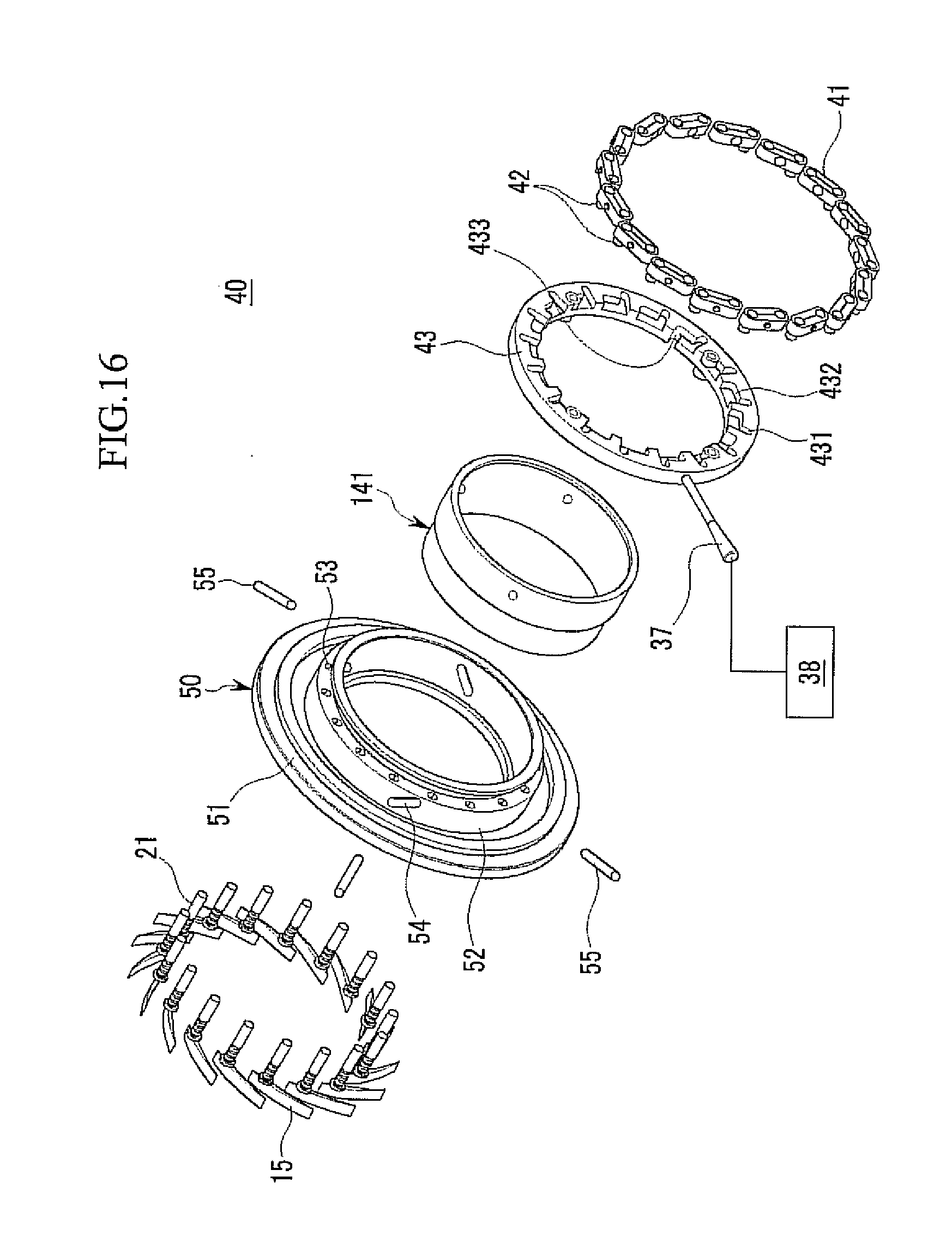
[0110] FIG. 16 is an exploded perspective view of a variable diffuser system in the gas compressor 200 shown in FIG. 14 and FIG. 17 is a partially enlarged diagram of FIG. 16.
[0111] Referring to FIGS. 16 and 17, the plurality of veins 15 are arranged at regular intervals in a circumferential direction of the diffuser passage 17 at one portion of the diffuser frame 50 and a vein shaft 21 is fixed to each vein 15.
[0112] The diffuser frame 50 includes a ring-shaped flange 51 and a cylindrical support portion 52 extending from the inside of the flange 51 with a predetermined height. The flange 51 is placed to face the discharge scroll 18 inside the shroud 132 to form the diffuser passage 17 between the flange 51 and the discharge scroll 18. The support portion 52 extends in a direction farther from the discharge scroll 18 from the inside of the flange 51.
[0113] A plurality of vein holes 53 penetrating the support portion 52 in a direction parallel to the rotation shaft 11 are formed in the support portion 52. In addition, each vein shaft 21 is inserted into the vein hole 53, such that the vein 15 and the vein shaft 21 are supported by the diffuser frame 50. In this case, the length of the vein shaft 21 is larger than the height of the support portion 52 and after the vein shaft 21 is coupled to the diffuser frame 50, the end of the vein shaft 21 protrudes outside the support portion 52.
[0114] The end of the vein shaft 21 is fixed to one end of a link member 41 and a guide shaft 42 is fixed to one opposite end of the link member 41 with a predetermined distance from the vein shaft 21. The link member 41 and the guide shaft 42 are provided as many as the vein shafts 21 and the guide shaft 42 is shorter than the vein shaft 21. As the vein shaft 21 is connected with the guide shaft 42 through the link member 41, when the guide shaft 42 rotatably moves around the vein shaft 21, the vein shaft 21 rotates to control opening and closing degrees of the vein 15.
[0115] The ring valve 141 is coupled to the inside of the support portion 52 and an outer surface of the ring valve 141 is closely attached to an inner surface of the support portion 52. A plurality of slant sliding holes 54 penetrating the support portion 52 in the radial direction of the impeller 12 are formed in the support portion 52. The slant sliding hole 54 is positioned between two adjacent vein holes 53 not to be connected with the vein hole 53 and placed to be slant in a direction parallel to the rotation shaft 11.
[0116] FIG. 18 is a perspective view showing a combined state of the diffuser frame 50 and the ring valve 141 shown in FIG. 17.
[0117] Referring to FIG. 18, after the ring valve 141 is coupled to the inside of the support portion 52, a plurality of fixing keys 55 penetrate the slant sliding holes 54 outside the support portion 52 and thereafter, are fixed to the ring valve 141. In this case, the end of the fixing key 55 protrudes outside the support portion 52. In addition, the width of the fixing key 55 is smaller than that of the slant sliding hole 54, such that the fixing key 55 moves in a longitudinal direction of the slant sliding hole 54.
[0118] When the fixing key 55 is positioned at the end of the slant sliding hole 54 which is faraway from the flange 51, the ring valve 141 is positioned with a distance from the discharge scroll 18 to open the diffuser passage 17. On the contrary, when the fixing key 55 is positioned at the end of the slant sliding hole 54 toward the flange 51, the ring valve 141 contacts the discharge scroll 18 to seal the diffuser passage 17. The former is indicated by a solid line and the latter is indicated by dotted lines.
[0119] Referring back to FIGS. 16 and 17, a ring-shaped control member 43 is installed outside the support portion 52. The control member 43 is coupled with the fixing key 55 to move the fixing key 55, thereby controlling forward and backward movements of the ring valve 141. At the same time, the control member 43 is coupled with even the guide shaft 42 to rotatably move the guide shaft 42, thereby controlling a rotational angle of the vein 15. In the gas compressor 200 of the second exemplary embodiment, the control member 43, the plurality of link members 41, the plurality of guide shafts 42, and the plurality of fixing keys 55 constitute the actuator 40.
[0120] A plurality of guide grooves 433 are formed on one surface of the control member 43 in the radial direction. In addition, second guide grooves 432 connected with the first guide grooves 431 are formed in a circumferential direction of the control member 43. The first and second guide grooves 431 and 432 are provided as many as the vein shafts 21. Further, third guide grooves 433 are formed on an inner surface of the control member 43 in a thickness direction of the control member 43. The third guide grooves 433 are provided as many as the fixing keys 55 and are finked with the second guide grooves 432.
[0121] The guide shaft 42 is received in the first and second guide grooves 431 and 432 to move along the first and second guide grooves 431 and 432 when the control member 43 rotates. The fixing key 55 is received in the third guide groove 433 to move along the third guide groove 433 when the control member 43 rotates. A control handle 37 transmitting rotating power to the control member 43 is positioned on an outer surface of the control member 43. The control handle 37 is connected with the control unit 38 to be operated by the command from the control unit 38.
[0122] FIG. 19 is a right side view of the variable diffuser system in the gas compressor 200 shown in FIG. 14 and FIG. 20 is a partially enlarged perspective view showing a part of the control member 43 and the guide shaft 42 and the fixing key 55 in a configuration of the variable diffuser system shown in FIG. 19.
[0123] Referring to FIGS. 19 and 20, the control member 43 sequentially controls the position of the ring valve 141 and the rotational angle of the vein 15 depending on the rotational direction and the rotational angle. That is, a movement amount of the ring valve 141 is controlled through the rotation of the control member 43 in a first section between point (a) and point (b). In addition, the rotational angle of the vein 15 is controlled through the rotation of the control member 43 in a second section between point (b) and point (c).
[0124] First, the fixing key 55 at point (a) is positioned at the end of the slant sliding hole 54 toward the discharge scroll 18 (see a dotted line mark of FIG. 18). Therefore, the ring valve 141 contacts the discharge scroll 18 to seal the diffuser passage 17. In this case, the end of the fixing key 55 is positioned at the end of the third guide groove 433 toward the discharge scroll 18. Further, the guide shaft 42 at point (a) is positioned at the end of the second guide groove 432 which is faraway from the first guide groove 431. In this state, a slant angle of the vein 15 to a tangent line of the outer surface of the ring valve 141 is minimized to reduce an area of the diffuser passage 17.
[0125] When the control handle 37 moves toward point (b) from point (a) to rotate the control member 43 in the counterclockwise direction, the fixing key 55 moves in a direction which is faraway from the discharge scroll 18 along the third guide groove 433. Therefore, the ring valve 141 moves backwards to open the diffuser passage 17.
[0126] The position of the guide shaft 42 does not vary in a first section, but the guide shaft 42 is positioned at the end of the second guide groove 432 which is linked with the first guide groove 431 at point (b) due to the rotation of the control member 43. Since the position of the guide shaft 42 does not vary in the first section, the vein 15 maintains the closed state as it is. As described above, in the first section, the movement amount of the ring valve 14 can be controlled without variation in rotational angle of the vein 15.
[0127] When the control handle 37 moves toward point (c) from point (b) to further rotate the control member 43 in the counterclockwise direction, the guide shaft 42 slidably moves along the first guide groove 431 to rotate the vein shaft 21. Therefore, the vein 15 rotates so that the slant angle of the vein 15 to the tangent line of the outer surface of the ring valve 141 is maximized, thereby increasing the area of the diffuser passage 17.
[0128] The position of the fixing key 55 does not vary in the second section, but the fixing key 55 is positioned at the end of the second guide groove 432 which is linked with the first guide groove 431 at point (c) due to the rotation of the control member 43. Since the position of the fixing key 55 does not vary in the second section, the ring valve 141 maintains the opened state as it is. As described above, in the second section, the rotational angle of the vein 15 can be controlled without the movement of the ring valve 141.
[0129] Referring to FIGS. 21 to 23, a method for controlling the flow rate using the variable diffuser system will be described.
[0130] FIG. 21 is a perspective view showing states of the ring valve 141 and the vein 15 at point (a) shown in FIG. 19.
[0131] Referring to FIG. 21, in initial operation, the ring valve 141 ascends from the diffuser frame 50 to seal the diffuser passage 17. In addition, the plurality of veins 15 maintain the closed state to reduce an area of the diffuser passage 17 outside the ring valve 141 (step S1). As described above, when the operation of the gas compressor 200 starts with the diffuser passage 17 sealed with the ring valve 141, no-load operation can be implemented. Further, stall and surge can be suppressed by preventing backflow of compressed gas.
[0132] FIG. 22 is a perspective view showing states of the ring valve 141 and the vein 15 at point (b) shown in FIG. 19.
[0133] Referring to FIG. 22, when the control handle 37 and the control member 43 are rotated in the counterclockwise direction (based on FIG. 19) for rated operation, the fixing key 55 moves backwards the ring valve 141 while moving along the third guide groove 433 to open the diffuser passage 17 at the position of the ring valve 141 (step S2). In this case, the plurality of veins 15 maintain an initial state as it is.
[0134] FIG. 23 is a perspective view showing states of the ring valve 141 and the vein 15 at point (c) shown in FIG. 19.
[0135] Referring to FIG. 23, when the control handle 37 and the control member 43 are further rotated in the counterclockwise direction (based on FIG. 19), the guide shaft 42 rotates the vein shaft 21 while moving along the first guide groove 431. Therefore, the plurality of veins 15 moves to the maximum flow rate position to open the diffuser passage 17 (step S3).
[0136] The rated operation is performed in step S3 and the area of the diffuser passage 17 is varied for stabilization of air current by controlling the vein 15 depending on an operational state sensed by the control unit 38. Further, when the backflow of gas toward the impeller, which is caused due to a problem in a used place is sensed in the rated operation, the variable diffuser system returns to an initial position shown in FIG. 11 to seal the diffuser passage 17 with the ring valve 141, thereby preventing the surge.
[0137] An operational sequence for the stop is in reverse order to the above-mentioned process.
[0138] When the control handle 37 and the control member 43 are rotated in the clockwise direction (based on FIG. 19), the area of the diffuser passage 17 is reduced while the vein 15 is closed as shown in FIG. 22 (step S4). Thereafter, when the control handle 37 and the control member 43 are further rotated in the clockwise direction (based on FIG. 19), the ring valve 141 ascends from the diffuser frame 50 to seal the diffuser passage 17 as shown in FIG. 21 (step S5). Therefore, even for a period from the rated operation to the stopping of the impeller 12, the surge can be effectively suppressed.
[0139] FIG. 24 is a partial cross-sectional view of a gas compressor 300 according to a third exemplary embodiment of the present invention.
[0140] Referring to FIG. 24, the gas compressor 300 of the third exemplary embodiment has a configuration in which a plurality of veins 15 and a ring valve 142 are controlled by different actuators unlike the second exemplary embodiment. That is, the gas compressor 300 of the third exemplary embodiment includes a first actuator 60 coupled with the vein shaft 21 to control the rotational angle of the vein 15, and a second actuator 70 controlling forward and backward movements of the ring valve 142 by using compressed air.
[0141] Basic configurations and operations of the vein 15 and the ring valve 142 are same as in the second exemplary embodiment except for the structures of the first and second actuators 60 and 70. The same reference numerals refer to the same members as the second exemplary embodiment and members different from the second exemplary embodiment will be primarily described below.
[0142] FIG. 25 is an exploded perspective view of a variable diffuser system in the gas compressor 300 shown in FIG. 24 and FIG. 26 is a right side view of the variable diffuser system shown in FIG. 24.
[0143] Referring to FIGS. 25 and 26, the shapes of the vein 15 and the vein shaft 21 are the same as in the second exemplary embodiment. The shape of a diffuser frame 56 is the same as in the second exemplary embodiment except that a slant sliding hole is not formed in the support portion 52 but a first nozzle 71 to be described below is formed in the diffuser frame 56.
[0144] A plurality of first guide grooves 441 are formed on one surface of a control member 44 in a radial direction. After the vein shaft 21 is coupled to the diffuser frame 56, the end thereof protrudes outside the support portion 52, and the end of the vein shaft 21 is fixed to one end of a link member 41. A guide shaft 42 is fixed to one opposite end of the link member 41 with a predetermined distance from the vein shaft 21. The guide shaft 42 is received in the first guide groove 441 and the link member 41 is placed in parallel to the radial direction. A control handle 37 transmitting rotating power to the control member 44 is positioned on an outer surface of the control member 44.
[0145] In the third exemplary embodiment, the plurality of link members 41, the plurality of guide shafts 42, and the control member 44 constitute the first actuator 60. When the control member 44 is rotated in the clockwise direction (based on FIG. 26), the area of the diffuser passage 17 is increased by rotating the vein shaft 21 and the vein 15 in the same direction while the guide shaft 42 rotates along the first guide groove 441 in the clockwise direction. On the contrary, when the control member 44 is rotated in the counterclockwise direction (based on FIG. 26), the area of the diffuser passage 17 is decreased by rotating the vein shaft 21 and the vein 15 in the same direction while the guide shaft 42 rotates along the first guide groove 441 in the counterclockwise direction.
[0146] FIG. 27 is a partially enlarged diagram of the gas compressor 300 shown in FIG. 24 and shows a state in which the ring valve 142 moves forwards toward the discharge scroll 18 to seal the diffuser passage 17.
[0147] Referring to FIGS. 25 and 27, an extension ring 143 is formed on an outer surface of the ring valve 142 and the outer surface of the extension ring 143 is coupled to the inside of the support portion 152 to be closely attached to an inner surface of the support portion 52. A top cover 45 is installed between the support portion 52 and the ring valve 142 and the top cover 45 is fixed to the support portion 52 through screw connection. The ring valve 142 maintains a gap G from the end of the impeller 12, which meets Condition (1) in the radial direction of the impeller 12 at the outlet of the impeller 12 like the second exemplary embodiment.
[0148] The second actuator 70 includes a first nozzle 71 which is formed in the top cover 45 and the support portion 52 and sprays compressed air toward one surface (a left side surface of the extension ring based on FIG. 27) of the extension ring 143 toward the diffuser passage 17, and a second nozzle 72 which is formed on the top cover 45 and sprays compressed air toward the other surface (a right side surface of the extension ring based on FIG. 27) of the extension ring 143 which is faraway from the diffuser passage 17.
[0149] Therefore, when the first nozzle 71 is opened to spray the compressed air through the first nozzle 71, the extension ring 143 moves backwards the ring valve 142 by receiving force in a direction which is faraway from the discharge scroll 18 to open the diffuser passage 17. On the contrary, when the second nozzle 72 is opened to spray the compressed air through the second nozzle 72, the extension ring 143 moves forwards the ring valve 142 by receiving force toward the discharge scroll 18 to seal the diffuser passage 17.
[0150] In the variable diffuser system of the third exemplary embodiment, the control handle 37 of the first actuator 60 and the first and second nozzles 71 and 72 of the second actuator 70 are connected with the control unit 38 to operate sequentially according to the command from the control unit 38. The method for controlling the flow rate of the gas compressor 300 using the ring valve 142 and the plurality of veins 15 is the same as in the second exemplary embodiment.
[0151] Meanwhile, in FIGS. 12 and 27, a structure in which the spaces among the blades 16 can be in communication with each other over the wing surface 161 inside the shroud 132 is shown, but a structure in which a cover plate (not shown) is fixed to the wing surface 161 to separate the spaces among the blades 16 from each other on the wing surface 161 can also be applied.
[0152] While this invention has been described in connection with what is presently considered to be practical exemplary embodiments, it is to be understood that the invention is not limited to the disclosed embodiments, but, on the contrary, is intended to cover various modifications and equivalent arrangements included within the spirit and scope of the appended claims.
* * * * *
D00000
D00001
D00002
D00003
D00004
D00005
D00006
D00007
D00008
D00009
D00010
D00011
D00012
D00013
D00014

D00015
D00016
D00017
D00018
D00019

D00020
D00021
D00022
D00023
D00024
D00025
D00026
D00027
XML
uspto.report is an independent third-party trademark research tool that is not affiliated, endorsed, or sponsored by the United States Patent and Trademark Office (USPTO) or any other governmental organization. The information provided by uspto.report is based on publicly available data at the time of writing and is intended for informational purposes only.
While we strive to provide accurate and up-to-date information, we do not guarantee the accuracy, completeness, reliability, or suitability of the information displayed on this site. The use of this site is at your own risk. Any reliance you place on such information is therefore strictly at your own risk.
All official trademark data, including owner information, should be verified by visiting the official USPTO website at www.uspto.gov. This site is not intended to replace professional legal advice and should not be used as a substitute for consulting with a legal professional who is knowledgeable about trademark law.