Display Module
Ling; Kuo-Nan ; et al.
U.S. patent application number 13/171482 was filed with the patent office on 2011-12-29 for display module. This patent application is currently assigned to COMPAL ELECTRONICS, INC.. Invention is credited to Yung-Hui Chen, Po-An Lin, Kuo-Nan Ling.
| Application Number | 20110317087 13/171482 |
| Document ID | / |
| Family ID | 45351399 |
| Filed Date | 2011-12-29 |


| United States Patent Application | 20110317087 |
| Kind Code | A1 |
| Ling; Kuo-Nan ; et al. | December 29, 2011 |
DISPLAY MODULE
Abstract
A display module includes a panel module and a frame and is able to be assembled to a cover to form a display device. A first fixing portion on a sidewall of the cover is snapped to a second fixing portion of the frame, such that the cover is fixed on the display module to form the display device. The panel module includes a first and a second sides, wherein the first side has a display region, and the panel module is adhered to the frame by the second side, such that the frame is the only structure substantially providing support to the panel module. When the display module has a backlight source, the panel module includes a glass module and a back light module. When the display module has no backlight source, the panel module only includes a glass module.
| Inventors: | Ling; Kuo-Nan; (Taipei City, TW) ; Lin; Po-An; (Taipei City, TW) ; Chen; Yung-Hui; (Taipei City, TW) |
| Assignee: | COMPAL ELECTRONICS, INC. Taipei City TW |
| Family ID: | 45351399 |
| Appl. No.: | 13/171482 |
| Filed: | June 29, 2011 |
Related U.S. Patent Documents
| Application Number | Filing Date | Patent Number | ||
|---|---|---|---|---|
| 61359811 | Jun 29, 2010 | |||
| Current U.S. Class: | 349/58 |
| Current CPC Class: | G06F 1/1601 20130101; H05K 5/02 20130101; Y10T 16/554 20150115; G02F 2201/465 20130101; G02F 2202/28 20130101; G09F 2013/222 20130101; Y10T 156/10 20150115; G02F 1/133317 20210101; G06F 1/1616 20130101; G02B 6/0088 20130101; G02F 1/13332 20210101; G02F 1/133331 20210101 |
| Class at Publication: | 349/58 |
| International Class: | G02F 1/1333 20060101 G02F001/1333 |
Claims
1. A display module, comprising: a frame having an opening; and a panel module having a first side and a second side and the second side being adhered to the frame and covering the opening, wherein the first side comprises a display region and the frame is the only structure substantially providing support to the panel module.
2. The display module as claimed in claim 1, wherein the panel module is substantially securely affixed to the frame by an adhesive, and the adhesive comprises an epoxy resin.
3. The display module as claimed in claim 1, wherein the frame surrounds the panel module and is adhered to the panel module.
4. The display module as claimed in claim 1, wherein the opening increases a brightness of the display region.
5. The display module as claimed in claim 1, wherein the display module has a backlight source, the panel module comprises a glass module and a backlight module and the frame comprises a first supporting portion and a second supporting portion, the glass module is adhered to the first supporting portion along a direction, and the backlight module is adhered to the second supporting portion along the direction.
6. The display module as claimed in claim 5, wherein the first supporting portion is located on the frame at a position outer than that of the second supporting portion.
7. The display module as claimed in claim 1, wherein the display module does not have a backlight source, the panel module comprises a glass module and the frame comprises a supporting portion, wherein the glass module is adhered to the supporting portion, the glass module comprises a first glass plate and a second glass plate, and an organic light emitting layer is disposed between the first glass plate and the second glass plate.
8. The display module as claimed in claim 1, wherein the display module is further fixed to a cover through the frame, and the display module and the cover are combined to form a display device, the cover comprises a first fixing portion and the frame comprises a second fixing portion, and when the first fixing portion is snapped to the second fixing portion, the cover is fixed to the frame.
9. The display module as claimed in claim 8, wherein the display device further comprises a trim strip, and the trim strip surrounds periphery of the panel module to protect the panel module.
10. The display module as claimed in claim 8, wherein after the cover is fixed to the frame, a sidewall of the cover covers a sidewall of the frame to avoid light leakage of the display device.
11. A display device, comprising: a frame; a panel module having a first side and a second side, and the second side being adhered to the frame, wherein the first side comprises a display region; and a cover fixed to the frame and adjacent to the second side to form the display device, wherein the frame and the cover substantially provide support to panel module.
12. The display device as claimed in claim 11, wherein the panel module is substantially securely affixed to the frame by an adhesive, and the adhesive comprises an epoxy resin.
13. The display device as claimed in claim 11, wherein the display module has a backlight source, the panel module comprises a glass module and a backlight module and the frame comprises a first supporting portion and a second supporting portion, the glass module is adhered to the first supporting portion along a direction, and the backlight module is adhered to the second supporting portion along the direction.
14. The display device as claimed in claim 13, wherein the first supporting portion is located on the frame at a position outer than that of the second supporting portion.
15. The display device as claimed in claim 13, wherein the backlight module comprises a light source, a reflector plate, light guide plate, and an optical film set, and the light source comprises a lamp tube or a light emitting diode (LED) lamp bar.
16. The display device as claimed in claim 13, wherein the display module does not have a backlight source, the panel module comprises a glass module and the frame comprises a supporting portion, wherein the glass module is adhered to the supporting portion, the glass module comprises a first glass plate and a second glass plate, and an organic light emitting layer is disposed between the first glass plate and the second glass plate.
17. The display device as claimed in claim 11, wherein the cover comprises a first fixing portion, and the frame comprises a second fixing portion, and when the first fixing portion is snapped to the second fixing portion, the cover is fixed to the frame.
18. The display device as claimed in claim 11, further comprising: a trim strip surrounding periphery of the panel module to protect the panel module.
19. The display device as claimed in claim 11, further comprising: a trim cover covering a driving module plate connected to the panel module.
20. The display device as claimed in claim 11, wherein after the cover is fixed to the frame, a sidewall of the cover covers a sidewall of the frame to avoid light leakage of the display device.
Description
CROSS-REFERENCE TO RELATED APPLICATION
[0001] This application claims the priority benefits of U.S. provisional application Ser. No. 61/359,811, filed on Jun. 29, 2010. The entirety of the above-mentioned patent applications is hereby incorporated by reference herein and made a part of this specification.
BACKGROUND OF THE INVENTION
[0002] 1. Field of the Invention
[0003] The invention relates to a display module. Particularly, the invention relates to a display module used in an display device.
[0004] 2. Description of Related Art
[0005] Along with development of semiconductor devices and display techniques, electronic products are continually developed towards directions of miniaturization, multi-function and easy to carry. The commonly used portable electronic products include notebook computers, tablet computers and mobile phones, etc. Taking the notebook computer as an example, it is consisted of a host and a display device pivotally connected to each other. The user can close the host and the display device of the notebook computer to facilitate carrying around, and when the notebook computer is to be used, the display device is opened relative to the host to facilitate operation and viewing displayed images.
[0006] The display device of the notebook computer includes a housing and a panel module and a backlight module disposed in the housing. Generally, the panel module and the backlight module are fixed to a cover of the housing through screw-locking. In order to provide a space for screw-locking, the housing has to have a certain degree of thickness and screw holes have to be set at periphery of the panel module, so that the thinness of the display device and a display region thereof are limited.
SUMMARY OF THE INVENTION
[0007] The invention is directed to a display device, which has relatively thin thickness and relatively large display region.
[0008] The invention provides a display module including a frame and a panel module, where the frame has an opening and the panel module has a first side and a second side. The panel module is adhered to the frame and covers the opening to fix the panel module to the frame, where the first side of the panel module includes a display region, and the frame is the only structure substantially providing support to the panel module.
[0009] The invention provides a display device including a frame, a panel module and a cover. The panel module has a first side and a second side. The panel module is adhered to the frame to form a display module. The cover is fixed to the frame and is adjacent to the second side of the panel module to form the display device, where the frame and the cover provide support to the panel module.
[0010] The invention provides a method for assembling a display module, which includes following steps. First, a frame having an opening and a panel module having a first side and a second side are provided. Then, a second side of a panel module is adhered to the frame and covers the opening to form the display module, where a first side of the panel module includes a display region and the frame is the only structure substantially providing support to the panel module.
[0011] The invention provides a method for assembling a display device, which includes following steps. First a frame and a panel module having a first side and a second side are provided. Then, a second side of a panel module is adhered to the frame to form a display module, where a first side of the panel module includes a display region. Finally, a cover is fixed to the frame and the cover is adjacent to the second side of the panel module to form the display device, where the frame and the cover provide support to the panel module.
[0012] In an embodiment of the invention, the panel module is substantially securely affixed to the frame by an adhesive, and the adhesive includes an epoxy resin.
[0013] In an embodiment of the invention, the frame surrounds the panel module and is adhered to the panel module.
[0014] In an embodiment of the invention, the opening of the frame is used to increase a brightness of the display region.
[0015] In an embodiment of the invention, the display module has a backlight source.
[0016] In an embodiment of the invention, the panel module includes a glass module and a backlight module, and the frame includes a first supporting portion and a second supporting portion.
[0017] In an embodiment of the invention, the glass module is adhered to the first supporting portion along a direction, and the backlight module is adhered to the second supporting portion along the direction.
[0018] In an embodiment of the invention, the direction is a normal vector of the display region.
[0019] In an embodiment of the invention, the first supporting portion is located on the frame at a position outer than that of the second supporting portion.
[0020] In an embodiment of the invention, the first side and the second side of the panel module are planes parallel to each other.
[0021] In an embodiment of the invention, the backlight module includes a light source, a reflector plate, light guide plate, and an optical film set.
[0022] In an embodiment of the invention, the light source includes a lamp tube or a light emitting diode (LED) lamp bar.
[0023] In an embodiment of the invention, the glass module includes a first glass plate and a second glass plate, where a liquid crystal layer is formed between the first glass plate and the second glass plate.
[0024] In an embodiment of the invention, the display module does not have a backlight source.
[0025] In an embodiment of the invention, the panel module includes a glass module, and the frame includes a supporting portion.
[0026] In an embodiment of the invention, the glass module is adhered to the supporting portion, and the glass module includes a first glass plate and a second glass plate, where an organic light emitting layer is formed between the first glass plate and the second glass plate.
[0027] In an embodiment of the invention, the cover includes a first fixing portion, and the frame includes a second fixing portion.
[0028] In an embodiment of the invention, when the first fixing portion is snapped to the second fixing portion, the cover is fixed to the frame.
[0029] In an embodiment of the invention, the display device further includes a trim strip, and the trim strip surrounds periphery of the panel module to protect the panel module.
[0030] In an embodiment of the invention, the display device further includes a trim cover, and the trim cover is used to cover a driving module plate connected to the panel module.
[0031] In order to make the aforementioned and other features and advantages of the invention comprehensible, several exemplary embodiments accompanied with figures are described in detail below.
BRIEF DESCRIPTION OF THE DRAWINGS
[0032] The accompanying drawings are included to provide a further understanding of the invention, and are incorporated in and constitute a part of this specification. The drawings illustrate embodiments of the invention and, together with the description, serve to explain the principles of the invention.
[0033] FIG. 1 is a front view of a display device according to an embodiment of the invention.
[0034] FIG. 2 is a rear view of the display device of FIG. 1.
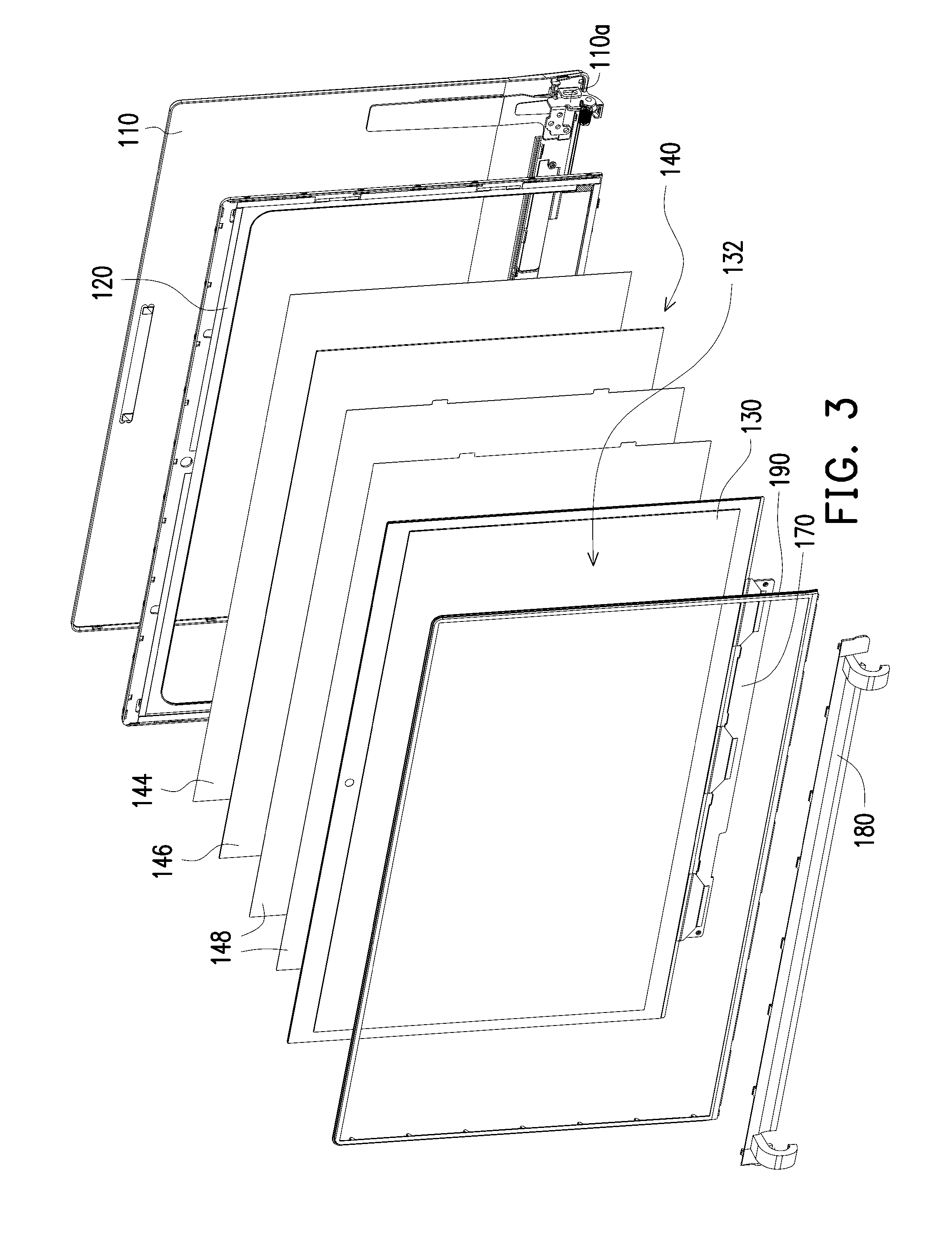
[0035] FIG. 3 is an exploded view of the display device of FIG. 1.
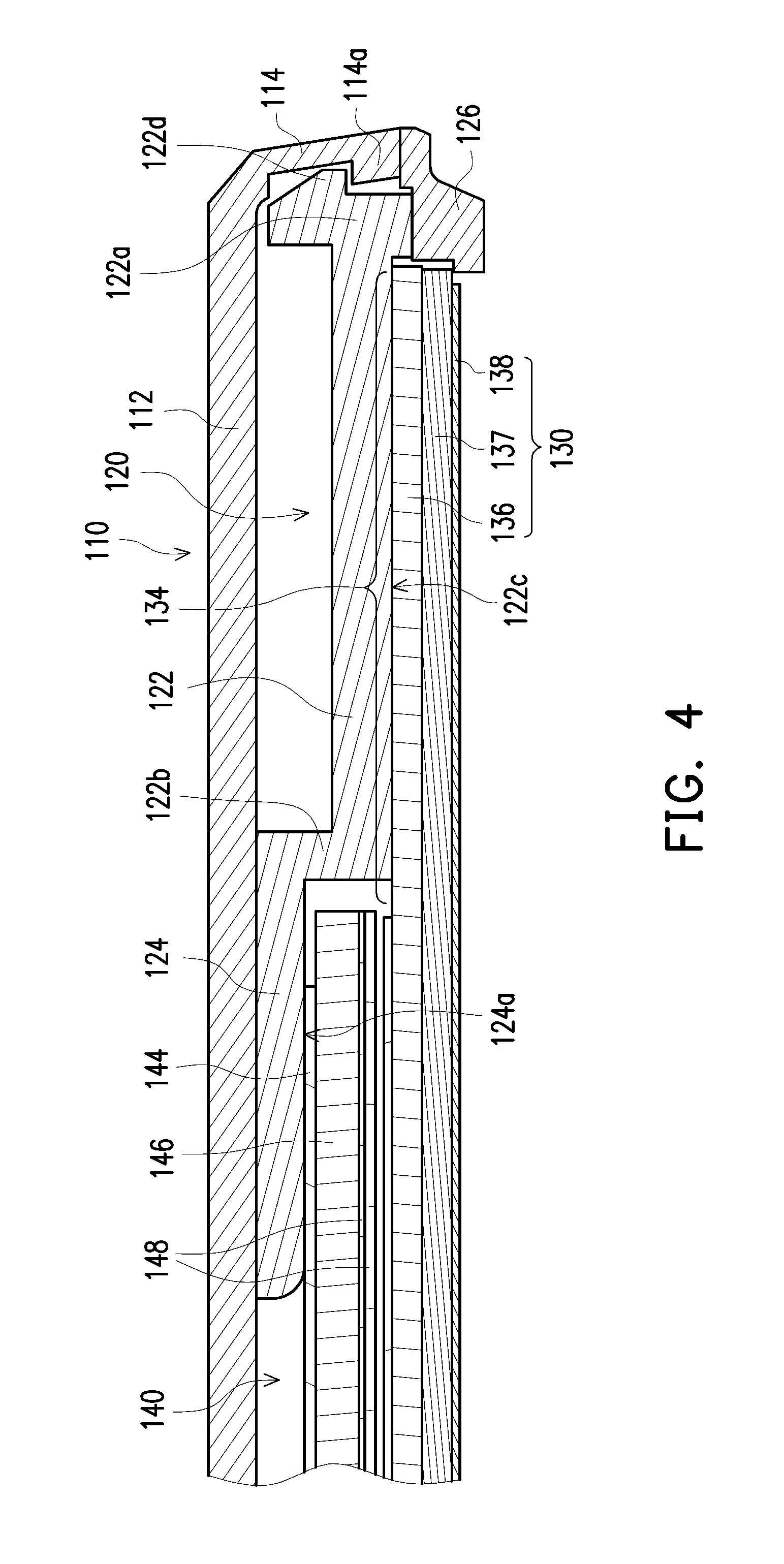
[0036] FIG. 4 is a cross-sectional view of part of the display device of FIG. 1.
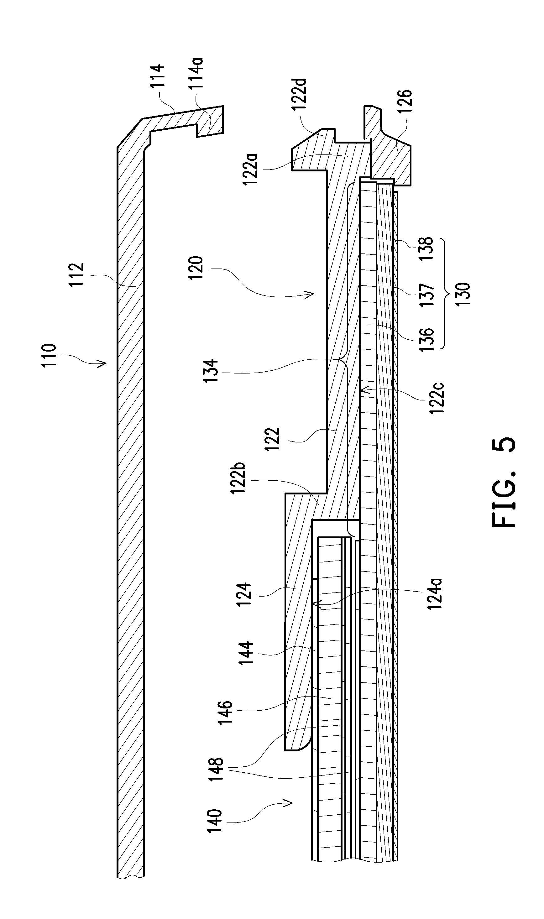
[0037] FIG. 5 illustrates the cover and the frame of FIG. 4 separated from each other.
[0038] FIG. 6 is a front view of the frame of FIG. 3.
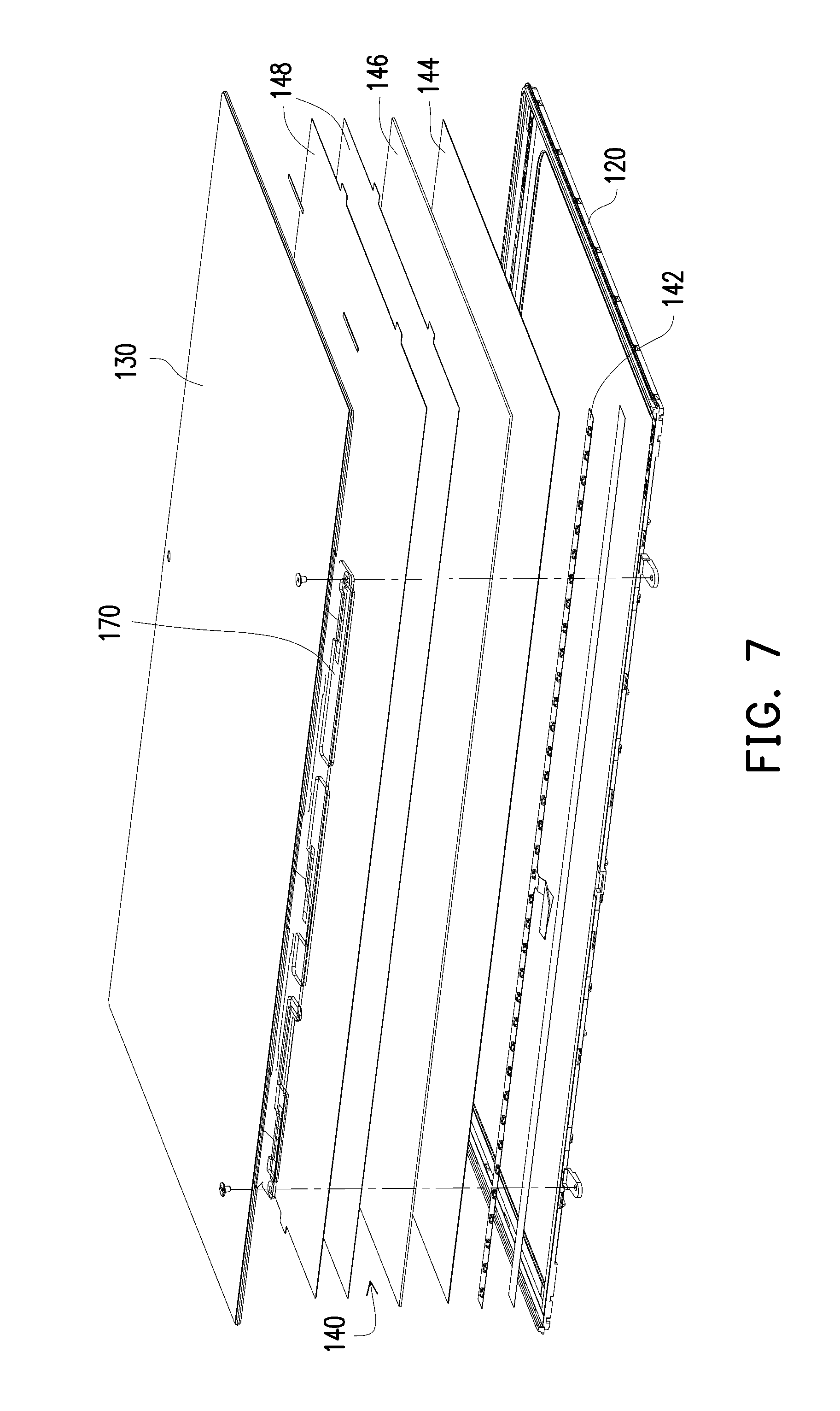
[0039] FIG. 7 is an exploded view of a part of members of the display device of FIG. 1.
[0040] FIG. 8A is a flowchart illustrating a method of assembling a display module according to an embodiment of the invention.
[0041] FIG. 8B is a flowchart illustrating a method of assembling a display device according to an embodiment of the invention.
DETAILED DESCRIPTION OF DISCLOSED EMBODIMENTS
[0042] FIG. 1 is a front view of a display device according to an embodiment of the invention. FIG. 2 is a rear view of the display device of FIG. 1. FIG. 3 is an exploded view of the display device of FIG. 1. The structure of the invention can be applied to a display device having a backlight source or a display device without a backlight source (a self-luminous display device), where the display device having the backlight source can be a liquid crystal display (LCD). The display device without the backlight source can be an organic light-emitting diode (OLED) display device. In the following first embodiment, the structure of the invention is applied to a display device having the backlight source, though the invention is not limited thereto. Referring to FIG. 1 to FIG. 3, the display device 100 of the first embodiment includes a cover 110, a frame 120 and a panel module, where the panel module includes a glass module 130 and a backlight module 140. The frame 120 can be fixed to the cover 110, and the panel module can be adhered to the frame 120 along a direction to form a display module, where the above direction is a normal line direction of a display region on the display module. When the display device 100 has a backlight source, the display module has the backlight source. The display device 100 of the first embodiment is, for example, applied to a notebook computer, and the display device 100 is pivotally connected to a host (not shown) of the notebook computer through a hinge 110a shown in FIG. 3 to form the notebook computer. In other embodiments, the display device 100 can also be applied to electronic devices such as a tablet computer, a mobile phone, and a television, etc.
[0043] FIG. 4 is a cross-sectional view of part of the display device of FIG. 1. Referring to FIG. 4, in detail, the cover 110 of the first embodiment has a base plate 112 and a sidewall 114, and the frame 120 has a supporting part protruded inward, and the supporting part includes a first supporting portion 122 and a second supporting portion 124. A first side 122a of the first supporting portion 122 is snapped to the sidewall 114 of the cover 110, and the second supporting portion 124 is connected to a second side 122b of the first supporting portion 122, and is leaned against or not leaned against the base plate 112 of the cover 110 according to a design requirement of the product. The glass module 130 is adhered to the first supporting portion 122 along a direction, and the backlight module 140 is disposed between the glass module 130 and the base plate 112, and is adhered to the second supporting portion 124 along the same direction, where the adhering direction of the glass module 130 and the backlight module 140 and the frame 120 is a normal line direction of a display region 132 of the display module. According to a design requirement of the product, the first supporting portion 122 is located on the frame at a position outer than that of the second supporting portion 124, so that the light of the light source can be totally transmitted to the glass module 130 through the backlight module 140. The frame 120 has an opening in the middle, and the light produced by the backlight module 140 can be fluently transmitted to the glass module 130 through the opening, so as to increase a brightness of the display region 132. When the panel module is adhered to the frame 120, the frame 120 surrounds the periphery of the panel module and the panel module covers the opening to increase the brightness of the display region 132. Moreover, according to a different product design, the frame 120 may further include a stop portion 126 to prevent the glass module 130 from departing the first supporting portion 122, so as to further protect the glass module 130. When the frame 120 does not have the stop portion 126, the display device 100 of the embodiment further includes a trim strip 190, and the trim strip 190 surrounds periphery of the glass module 130, and is engaged to the frame 120 or the cover 110 to protect a glass plate of the glass module 130 from cracking due to impact. The glass module 130 includes a first side and a second side, where the first side of the glass module 130 includes the display region 132 and is used to contact the stop portion 126 or the trim strip 190. The second side of the glass module 130 is contacted or adhered to the backlight module 140. The panel module also includes a first side and a second side, where the first side of the panel module is the first side of the glass module 130 and includes the display region 132. The second side of the panel module is used to adhere to the frame 120, so as to combine the panel module and the frame 120 to form the display module. The first side and the second side of the panel module are planes parallel to each other.
[0044] According to the above configuration, when the frame 120 has the stop portion 126, the glass module 130 and the backlight module 140 of the panel module are all fixed to the frame 120 through adhesion, and the frame 120 is snapped to the cover 110 and limits a position of the glass module 130 through the stop portion 126, so as to complete assembling the display module. Since the display module is not fixed to the cover 110 through screw-locking, the cover 110 is unnecessary to provide a screw-locking space, so that the whole structure may have a relatively thin thickness, and the display module may have a relatively large display region 132 (shown in FIG. 1 and FIG. 3) due to that configuration of screw holes is unnecessary. When the glass module 130 and the backlight module 140 of the panel module are substantially securely affixed to the frame 120 to from the display module by adhesion, the frame 120 is the only structure substantially providing support to the panel module. The display module and the cover 110 can be combined to form the display device 100 due to support of the frame 120.
[0045] In the first embodiment, a material of the first supporting portion 122 and the second supporting portion 124 is, for example, plastic having a cushion effect, which can provide support to the glass module 130 and the backlight module 140. A material of the stop portion 126 is, for example, rubber, which can be fabricated together with the first supporting portion 122 and the second supporting portion 124 through double injection molding to form an integral structure. A material of the cover 110 of the first embodiment is, for example, aluminium or other suitable metal materials. However, the invention is not limited thereto, and in other embodiments, the material of the cover 110 can also be plastic, and the cover 110 has integrally formed structural strengthening ribs or metal members used for improving a structural strength.
[0046] In detail, the first supporting portion 122 of the first embodiment has a first supporting surface 122c, and the second supporting portion 124 has a second supporting surface 124a. A distance between the first supporting surface 122c and the base plate 112 is greater than a distance between the second supporting surface 124a and the base plate 112. An orthogonal projection of a peripheral part 134 of the glass module 130 on the base plate 112 is not overlapped to an orthogonal projection of the backlight module 140 on the base plate 112. In this way, the glass module 130 and the backlight module 140 stacked to each other are respectively adhered to the first supporting surface 122c and the second supporting surface 124a, where the glass module 130 is adhered to the first supporting surface 122c through its peripheral part 134, and the adhesive used for adhering the panel module and the frame 120 includes an epoxy resin.
[0047] Moreover, the sidewall 114 of the cover 110 of the first embodiment has a first fixing portion 114a, and the first supporting portion 122 of the frame 120 has a second fixing portion 122d, and the first fixing portion 114a is snapped to the second fixing portion 122d to fix the cover 110 to the frame 120. After the cover 110 is fixed to the frame 120 to form the display device, the cover 110 is adjacent to the second side of the panel module, and the cover 110 and the frame 120 provide support to the panel module to strengthen a structural strength of the display module. After the cover 110 is fixed to the frame 120, the sidewall 114 of the cover 110 covers a sidewall of the corresponding frame 120 to avoid light leakage of the display device. FIG. 5 illustrates the cover and the frame of FIG. 4 separated from each other. Referring to FIG. 4 and FIG. 5, during assembling, the glass module 130 and the backlight module 140 are respectively adhered to the frame 120 as that shown in FIG. 5. Then, the first fixing portion 114a of the cover 110 is snapped to the second fixing portion 122d of the frame 120 to complete assembling the cover 110 and the frame 120 to form the display device.
[0048] FIG. 6 is a front view of the frame of FIG. 3. Referring to FIG. 1, FIG. 3 and FIG. 6, the display device 100 of the first embodiment further includes a lens module 150, an antenna 160 and a driving module plate 170. The lens module 150 and the antenna 160 are disposed on the frame 120, and the driving module plate 170 is connected to the glass module 130 and is assembled to the frame 120, where the driving module plate 170 is electrically connected to the glass module 130 to drive the glass module 130 to display images. The display device 100 of the first embodiment further includes a trim cover 180 and a trim strip 190, the trim cover 180 covers the driving module plate 170 stretching out from a side edge of the frame 120, and the trim strip 190 covers periphery of the glass module 130 and exposes the display region 132, so that the display device may have a better appearance and the glass plate on the glass module 130 is protected.
[0049] Referring to FIG. 4, when the display device 100 having the backlight source is an LCD, the glass module 130 of the first embodiment includes a first glass plate 136, a liquid crystal layer 137 and a second glass plate 138. The first glass plate 136 is located at the second side of the panel module and is adhered to the first supporting portion 122, the liquid crystal layer 137 is disposed between the first glass plate 136 and the second glass plate 138. The second glass plate 138 is located at the first side of the panel module, and is used to contact the stop portion 126 or the trim strip 190. Materials of the first glass plate 136 and the second glass plate 138 are, for example, transparent materials with a high strength, which can protect the liquid crystal layer 137 injected there between, and the light emitted from the backlight module 140 reaches the liquid crystal layer 137 through the first glass plate 136, and after the light is processed, the user can view the image displayed by the display module through the second glass plate 138.
[0050] FIG. 7 is an exploded view of a part of members of the display device of FIG. 1. Referring to FIG. 3, FIG. 4 and FIG. 7, the backlight module 140 of the first embodiment includes a light source 142, a reflector plate 144, a light guide plate 146 and an optical film set 148, where the light source can be a lamp tube or a light-emitting diode (LED) lamp bar. The lamp bar 142 and the reflector plate 144 are adhered to the second supporting portion 124 of the frame 120. The light guide plate 146 is disposed on the reflector pate 144, the optical film set 148 is disposed on the light guide plate 146, the light guide plate 146 is located between the reflector plate 144 and the optical film set 148, and the optical film set 148 is located between the light guide plate 146 and the glass module 130. One side of the light guide plate 146 is adjacent to the lamp bar 142, and the light emitted form the lamp bar 142 is suitable for entering the light guide plate 146 and is reflected by the reflector plate 144, and reaches the glass module 130 through the optical film set 138.
[0051] In a second embodiment of the invention, the display device does not have the backlight source. A main difference between the second embodiment and the first embodiment is that the display module may have an even light emitting effect without using the backlight module. When the display device without the backlight source is an OLED display device, an organic light emitting layer is generally packaged in the glass module 130 to replace the liquid crystal layer, so that the panel module only includes the glass module 130, and the supporting part of the frame 120 only has one supporting portion to support the panel module. When the panel module is adhered to the supporting portion of the frame 120, the frame 120 is the only structure substantially providing support to the panel module.
[0052] Referring to FIG. 8A, FIG. 8A is a flowchart illustrating a method of assembling a display module according to an embodiment of the invention. First, in step S602, a panel module is provided and the panel module includes a first side and a second side. Then in step S604, a frame is provided, where the frame has an opening. When the display module has the backlight source, the frame includes a supporting part having a first supporting portion and a second supporting portion. When the display module does not have the light source, the supporting part only has one supporting portion. In step S606, the second side of a panel module is adhered to the frame and covers the opening to form the display module, where the frame is the only structure substantially providing support to the panel module. The first side of the panel module includes a display region. When the display module has the backlight source, the panel module includes a glass module and a backlight module, where the backlight module is adhered to the second supporting portion, and then the glass module is adhered to the first supporting portion in the same direction such that the panel module is adhered to the frame to form the display module. When the display module does not have the backlight source, the panel module only includes the glass module, so that during the assembling, only the glass module is required to be adhered to the frame to form the display module.
[0053] Referring to FIG. 8B, FIG. 8B is a flowchart illustrating a method of assembling a display device according to an embodiment of the invention. First, in step S702, a frame is provided. Then, in step S704, a panel module is provided and the panel module includes a first side and a second side. When the display device has the backlight source, the frame includes a supporting part having a first supporting portion and a second supporting portion. When the display device does not have the light source, the supporting part only has one supporting portion. In step S706, the second side of a panel module is adhered to the frame to form a display module, where the first side of the panel module includes a display region. When the display module has the backlight source, the panel module includes a glass module and a backlight module, where the backlight module is first adhered to the second supporting portion, and then the glass module is adhered to the first supporting portion in the same direction such that the panel module is adhered to the frame to form the display module. When the display module does not have the backlight source, the panel module only includes the glass module, so that during the assembling, only the glass module is required to be adhered to the frame to form the display module. Finally, in step S708, a cover is fixed to the frame to form the display device, where a first fixing portion on a sidewall of the cover is snapped to a second fixing portion of the frame. After the cover is fixed to the frame, the cover and the frame provide support to the panel module to strengthen a structural strength of the display module. After the display device is formed, a trim strip is assembled around the panel module to protect the glass module, where the decoration frame can be engaged to the frame or the cover according to different product designs, which is not limited by the invention.
[0054] In summary, the panel module and the frame are adhered to form the display module, and the frame is the only structure substantially providing support to the panel module. Then, the cover is fixed to the frame to complete assembling the display device. Since the display module is fixed to the cover without using a screw-locking method, the cover is unnecessary to provide a screw-locking space, and the whole structure may have a relatively thin thickness. Moreover, the display module may have a relatively large display region due to that configuration of screw holes is unnecessary.
[0055] It will be apparent to those skilled in the art that various modifications and variations can be made to the structure of the invention without departing from the scope or spirit of the invention. In view of the foregoing, it is intended that the invention cover modifications and variations of this invention provided they fall within the scope of the following claims and their equivalents.
* * * * *
D00000
D00001
D00002
D00003
D00004
D00005
D00006
D00007
XML
uspto.report is an independent third-party trademark research tool that is not affiliated, endorsed, or sponsored by the United States Patent and Trademark Office (USPTO) or any other governmental organization. The information provided by uspto.report is based on publicly available data at the time of writing and is intended for informational purposes only.
While we strive to provide accurate and up-to-date information, we do not guarantee the accuracy, completeness, reliability, or suitability of the information displayed on this site. The use of this site is at your own risk. Any reliance you place on such information is therefore strictly at your own risk.
All official trademark data, including owner information, should be verified by visiting the official USPTO website at www.uspto.gov. This site is not intended to replace professional legal advice and should not be used as a substitute for consulting with a legal professional who is knowledgeable about trademark law.