Dressing aid
Whitlaw; Grady L.
U.S. patent application number 13/199469 was filed with the patent office on 2011-12-29 for dressing aid. Invention is credited to Grady L. Whitlaw.
| Application Number | 20110315724 13/199469 |
| Document ID | / |
| Family ID | 45351582 |
| Filed Date | 2011-12-29 |


View All Diagrams
| United States Patent Application | 20110315724 |
| Kind Code | A1 |
| Whitlaw; Grady L. | December 29, 2011 |
Dressing aid
Abstract
A dressing aid to assist individuals with limited lower back and/or knee flexibility don under and outer garments.
| Inventors: | Whitlaw; Grady L.; (Jackson, SC) |
| Family ID: | 45351582 |
| Appl. No.: | 13/199469 |
| Filed: | August 31, 2011 |
Related U.S. Patent Documents
| Application Number | Filing Date | Patent Number | ||
|---|---|---|---|---|
| 12002943 | Dec 19, 2007 | |||
| 13199469 | ||||
| 60963770 | Aug 7, 2007 | |||
| Current U.S. Class: | 223/111 |
| Current CPC Class: | A47G 25/90 20130101 |
| Class at Publication: | 223/111 |
| International Class: | A47G 25/90 20060101 A47G025/90 |
Claims
1. A device to assist physically challenged individuals don under and outer garments comprising: a length of connective material comprising a first end, a second end, and a mid-point; at least one pair of grip devices, wherein the first member of said at least one pair of grip devices is attached to said first end of said connective material and wherein the second member of said at least one pair of grip devices is attached to said second end of said connective material; and further wherein said device comprises a spreader element wherein said spreader element comprises a bar, and wherein said bar comprises a first pair of connector chases and a second pair of connector chases, and wherein the first end and the second end of said length of connective material are anchored, respectively, in the first and second members of the first pair of connection chases; and further wherein the first end of said first grip connector is attached to the first member of said at least one pair of grip devices and the first end of said grip connector is attached to the second member of said at least one pair of grip devices; and further wherein the second end of the first and of the second grip connector are anchored, respectively, in the first and second members of the second pair of connector chases.
2. A device to assist physically challenged individuals don under and outer garments comprising: a length of connective material comprising a first end, a second end, and a mid-point; at least one pair of grip devices, wherein the first member of said at least one pair of grip devices is attached to said first end of said connective material and wherein the second member of said at least one pair of grip devices is attached to said second end of said connective material; and further wherein said device comprises a spreader element, wherein said spreader element comprises a flat, inverted U-shaped plate wherein said inverted U-shaped plate comprises a top surface and a bottom surface, and further comprises a base, a first arm, a second arm, and a first pair of connector chases; wherein the first end of said length of connective material is attached to the first member of said first pair of connector chases and the second end of said length of connective material is attached to the second member of said first pair of connector chases, and further wherein, the first member of said at least one pair of grip devices is firmly anchored on said first arm and the second member of said at least one pair of grip devices is firmly anchored on the said second arm.
3. A device to assist physically challenged individuals don under and outer garments comprising: at length of connective material comprising a first end, a second end, and a mid-point; a least one pair of grip devices, wherein the first member of said at least one pair of grip devices is attached to said first end of said connective material and wherein the second member of said at least one pair of grip devices is attached to said second end of said connective material; and further wherein said device comprises a fixed spacer unit, wherein said fixed spacer unit comprises a cylinder, wherein said cylinder comprises a first end and a second end, and said cylinder further comprises a length and a diameter, and further wherein said cylinder comprises a first closing flap attached to said first end of said cylinder and a second closing flap attached to said second end of said spacer unit further comprises a rigid spacer unit, wherein said rigid spacer unit comprises a length and a diameter and wherein said spacer unit is positioned in said cylinder and held in position by said first and said second closing flap, and further wherein the first end of said cylinder is attached near the first end of said length of connective material and said second end of said cylinder is attached near the second end of said length of connective material such that the distance from the bottom of the cylinder to the tip of the grip device at each end of said length of connective material is approximately twice the length of the connective device.
4. the device to assist physically challenged individuals don under and outer garments of claim 3 wherein said connective material is web material.
Description
RELATION TO PRIOR APPLICATIONS
[0001] This application is a continuation-in-part of U.S. patent application Ser. No. 12/002,943 filed Dec. 19, 2007 which claims benefit of U.S. Provisional Patent Application 60/963,770 filed Aug. 7, 2007, and this application claims benefit of U.S. patent application Ser. No. 12/002,943 and of U.S. Provisional Patent Application 60/963,770, both of which applications are hereby incorporated in their entirety, by reference.
FIELD OF THE INVENTION
[0002] The invention is directed generally to the field of devices to aid the physically challenged as a result of injury, illness, or the infirmities of aging to dress. Specifically, it is a simple device to assist a physically challenged individual in donning undergarments and outer garments, pants or skirts, when the individual has restricted movement at the lower back, waist and/or knees.
BACKGROUND OF THE INVENTION
[0003] An individual for various reasons may be unable to bend to insert feet and legs into and through the leg openings of undergarments and pants or through a skirt, pull the garment into proper, comfortable position, and fasten the waist band of the garment. The inability to accomplish this seemingly simple, but very necessary task may be the result of temporary or permanent, limited flexibility of the waist, lower back and/or knees.
[0004] For many elderly individuals, as well as others suffering from certain diseases and injuries, including an increasingly young population of injured Military personnel, except for the physical challenges associated with lost flexibility in the back and knees and certain losses of mobility associated with such losses that are beyond the scope of this invention, a major need for assistance is in dressing. Devices to respond to this need are recognized as making a significant contribution to an individual's independence.
[0005] A wide variety of devices has been developed to assist physically challenged individuals in their daily lives. Dramatic improvements in wheel chairs and relted mobility devices are well known, and beyond the scope of this invention. Devices that are variously described or otherwise classified as "reachers" certainly must be considered in view of the current invention.
[0006] Reachers commonly comprise a rigid shaft of varying length with some type of "jaws" at one end that are operated by a manual trigger device at the other, handle end. Such devices are used effectively to retrieve items from the floor, tables, or shelves, and have been modified to assist an individual in putting on socks and shoes. Dressing aids, including the modified reachers noted above, have been developed for a variety of specific uses: long-handled shoe horns to help those that cannot easily bend from the waist; plastic sleeves to assist in putting on socks and stockings, frequently such devices includes a "pull-stick" to move the sock/stocking into position once it is positioned over the foot and ankle. Dressing sticks comprising a stiff shaft and soft "hook" at the opposite end of the grip area are used by some to help pull-up pants legs. Examples of a comprehensive array of dressing aids that are commercially available may be viewed by visiting, for example, www.sampsonspreston.com, or by examining the Sampsons Preston catalog.
[0007] Certain dressing aids and predecessor technology are the object of United States patents. Among early art is a "grab-stick," a shaft with pull action jaws to pick-up litter and a forerunner to "reachers" issued as U.S. Pat. No. 3,937,512 to Harold Baughman on Feb. 10, 1976. Also see U.S. Pat. No. 5,687,889 for a multipurpose dressing rod and reacher issued Nov. 18, 1997 to Douglas T. Liden.
[0008] Several patents involve technology specifically focused on putting socks or stockings on. See for example U.S. Pat. No. 3,604,604 issued Sep. 14, 1971 to Albert D. Ahn and U.S. Pat. No. 3,860,156 issued Jan. 14, 1975 to Ralph Lawrence.
[0009] In some instances, multiple uses are suggested as in the "shoe horn and cane" apparatus of U.S. Pat. No. 4,966,316 issued to Curtis L. George and Sandra L. George on Oct. 30, 1990. In other instances the use is very specific, such as the "body sleeve" of U.S. Pat. No. 6,044,491 issued to Sylvia N. Emory on Apr. 4, 2004 which is worn around the torso and attaches to undergarments and helps the individual don the undergarment then is unfastened and removed from the body.
[0010] Some commercially available technology is seemingly ultra-simple, such as the pair clip-like devices of used to join and hold an upper garment to a lower garment when dressing and fastening buttons and the like.
[0011] There remains room in the art for a device that will assist an individual with limited flexibility of the waist, lower back and/or knees to don undergarments, pants or a skirt starting from a semi-reclining, sitting, or standing position.
SUMMARY OF THE INVENTION
[0012] A first purpose and goal of the invention is a device adapted to assist individuals with restricted flexibility/mobility of the lower back and/or knees to don lower body clothing, both under and outer garments.
[0013] A second purpose and goal of the invention is a device that can be used by an individual starting in a seated position without assistance.
[0014] A third purpose and goal of the invention is a device that holds the waist-line of a garment open to facilitate positioning the garment over the feet and lower legs from a seated position.
[0015] A fourth purpose and goal of the invention is a spreader that facilitates holding the garment open and that provides a body by which the device can be manipulated to don a lower body garment.
[0016] A fifth purpose and goal of the invention is a device that will allow an individual to don lower body under and outer garments at the same time.
[0017] These and other purposes, goals, features, and benefits are achieved by a device the basic structure of which comprises a length of connective material (cord, light rope, or strap material, or the like) which is divided into two contiguous half lengths to which a grip device, such as an alligator clamp is connected at he end of each half length, such that the length of connective material may be securely attached to an inner or outer, lower body garment; an alternative configuration is a branch near each end of the length of connective material such that a member of a second pair of grip devices is connected to the end of each branch to allow to garments to be attached to the device; however, the grip device in the initial example may be adequately large to grip simultaneously a lower body under and outer garment; in an additional configuration, the ends of each half length of the connective material passes through a bar handle to separate the half lengths and the bar provides a grip by which the device may be manipulated; and in another configuration, the length of connective material is connected to a spreader device or fixed spreader unit such that the grip devices are separated and hold the fly of waist band open thereby allowing the feet and lower legs to be more conveniently positioned in the garment to which the device is attached and facilitate donning the garment starting from a seated position.
[0018] These and other purposes, features, and benefits of the invention will be better understood and appreciated by examination of the following descriptions, examples, and figures as well as examination of the appended claims.
BRIEF DESCRIPTION OF THE FIGURES
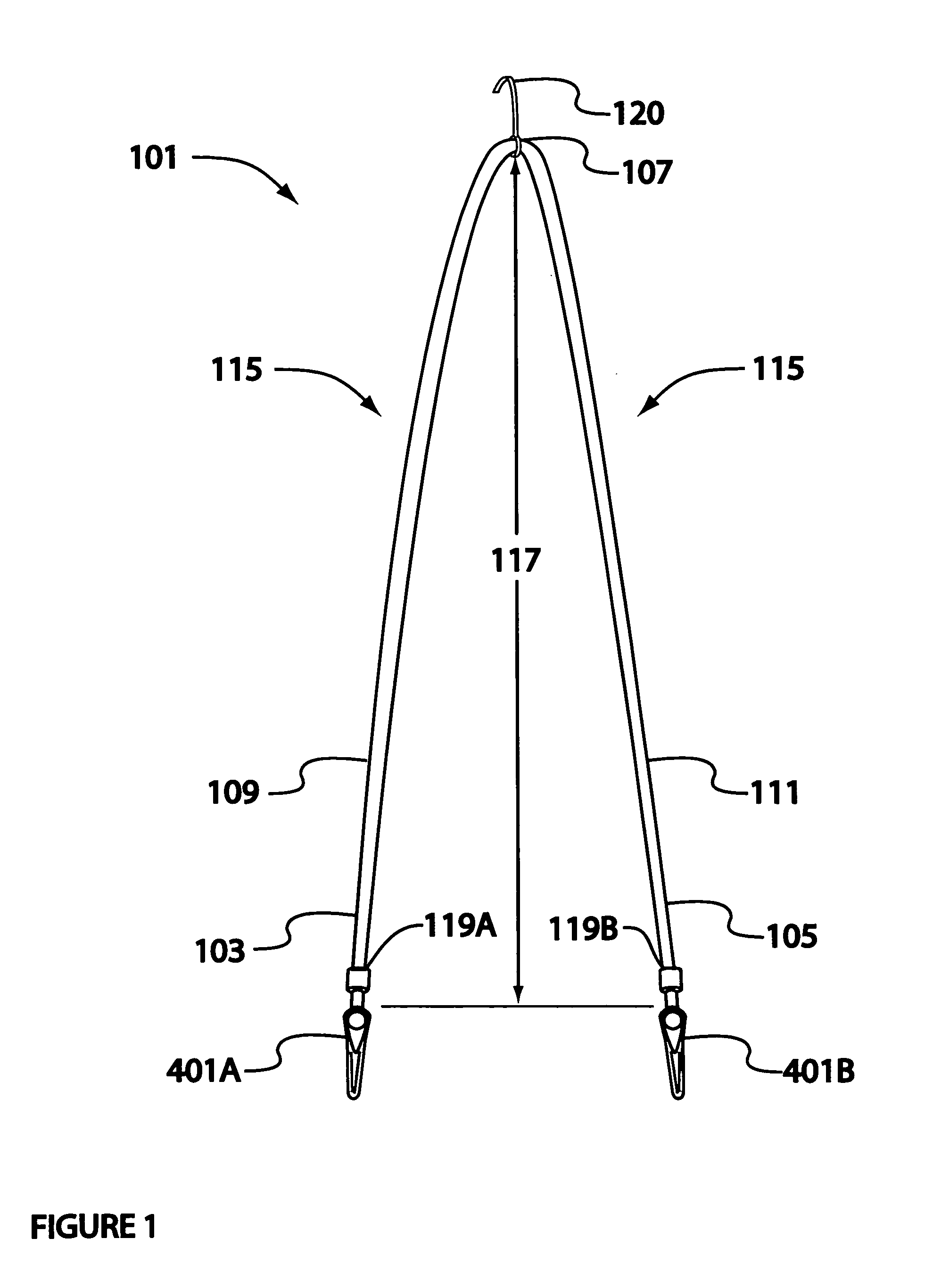
[0019] FIG. 1 illustrates the simplest configuration of the claimed dressing aid.
[0020] FIG. 2 illustrates the addition of a second pair of gripe devices to the dressing aid of FIG. 1.
[0021] FIG. 3 illustrates a modification of the dressing aid with the addition of a hand piece or tube element.
[0022] FIG. 4 illustrates the details alligator type of grip device.
[0023] FIG. 5A illustrates simplest configuration of claimed dressing aid connected to a pair of pants.
[0024] FIG. 5B illustrates an individual in a sitting position, with dressing aid in initial position to aid in donning pants.
[0025] FIG. 6A illustrates the configuration of the dressing aid when a bar element is attached as a spacer.
[0026] FIG. 6B illustrates an alternate attachment of the bar element devices for the dressing aid of FIG. 6A.
[0027] FIG. 6C illustrates the dressing aid attached to a pair of pants with the spacer bar properly positioned and attached.
[0028] FIG. 7A illustrates the configuration of the dressing aid in which the spreader element is an inverted U shaped plate element.
[0029] FIG. 7B illustrates an alternate attachment of the grip devices for the dressing aid of FIG. 7A.
[0030] FIG. 7C illustrates the dressing aid of FIG. 7A or 7B properly attached to a pair of pants.
[0031] FIG. 8A provides an overview of a dressing aid with a fixed spreader unit.
[0032] FIG. 8B provides details of the fixed spreader unit.
[0033] FIG. 8C illustrates one example of attachment of a grip device to web material.
EXAMPLES
Introduction
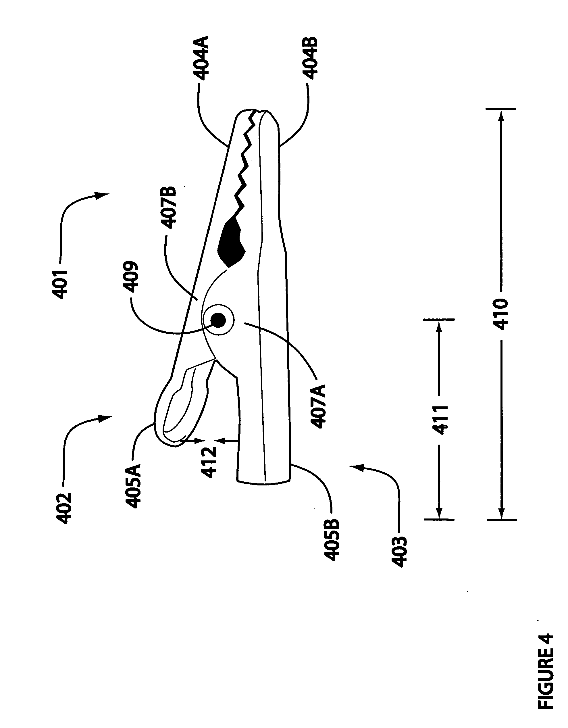
[0034] FIG. 1 and FIG. 2 illustrate variations of the basic dressing aid 101. A variety of devices may be adapted to connect an article of clothing to the dressing aid as has been discussed in detail previously (U.S. patent application Ser. No. 12/002,943). FIG. 4 illustrates the common alligator clamp device 401 by way of example, not limitation. Thus grip device 401 refers specifically to the alligator jaws clamp of FIG. 4 and to any clamp that may otherwise be used.
[0035] As illustrated in FIG. 4, the grip device 401, represented by an alligator clamp comprises a first (upper) half 402 and a second (lower) half 403. Each half comprises a grip end 404A and 404B and an operator arm 405A and 405B. Sides of each half have complimentary axle supports 407A and 407B (and 408A and 408B, not visible as illustrated in FIG. 4). An axle 409 supported by the complimentary axle supports 407A/B and 408A/B extends across the width of the device and mechanically connects the first 402 and second 403 halves. A compression spring is wound around the axle 409 and extends to the under surfaces of each operator arm 405A and 405B, separating, or holding the operator arms apart and forcing the grip ends 404A and 404B together and in physical contact with each other. Inward pressure on the operator arms (arrows 412) forces the arms to close and the grip ends to open; releasing the pressure causes the reverse action with the grip ends closing and securing material placed between them.
[0036] The strength of the gripe device is directly related to the strength of the spring (or force required to close the operator arms); this may vary, by way of example, not limitation, from less than 3 to 10 PSI adequately to secure a garment as it is drawn up during dressing by pulling on the length of connective material 115. The overall length 410 of the grip, by way of example, not limitation, varies from 1.0 to 3 inches, preferably 1.0 to 2.5 inches (2.5 to 7.5 cm, preferably 2.5 to 6.4 cm). The length 411 of the control arms 405A/B is normally half or more of the overall length of the grip device. Length of the control arm 411 as measured from its end to the axle 409 determines the force required to operate (open/close) the grip device and is a consideration in selecting an appropriate device. A wide variety of sizes and types of gripe devices is readily available through retail and wholesale hardware outlets known to one skilled in the art.
Example 1
[0037] FIG. 1 illustrates the simplest configuration of the invention. The dressing aid 101 of FIG. 1 comprises a length of connective material (cord, light rope, or strap material) 115 with a first end 103, a second end 105, and a mid-point 107. The mid-point 107 divides the length of connective material 115 into first half-length 109 and a second half-length 111. The length 117 of each half-length 109 and 111 is equal. The length 117 varies from 3 feet (1 m) to over 5 feet (2 m), or the overall length of the connective material 115 varies from less than 6 feet (2 m) to about 8 feet (2.4 m), although these values are reasonable examples, they do not constitute minimum or maximum values and are not limitations on the invention.
[0038] The dressing aid further comprises a first member of a first of a pair of grips 401A and a second member of a first pair of grips 401B. The first member of the first pair of grips 401A is firmly attached to the first end 103 of the length of connective material 115, and the second member of the first pair of grip devices 401B is similarly attached to the second end 105 of the length of connective material 115 at points 119A and 119B, respectively.
[0039] One arm of each member of the first pair of grip devices 401A/B may be secured to an end 103/105 of the length of connective material 115 in any of a variety of ways, for example, by using any of a variety of small clamp devices known to those skilled in the art, or with any of a variety of adhesives, depending on the materials from which both the grip device and connective material are made.
[0040] The length of connective material 115 may be natural, synthetic or any blend of materials commercially available and well known to those skilled in the art. Strength is not limiting, but minimum test should be approximately about 10 pounds (22 kg) with an upper limit for convenience of material of 25 pounds (55 kg). The connective material, if cord or rope, for convenience in handling, should be at least 0.25 inches in diameter (0.8 cm) to about 0.75 inch (1.9 cm), as a practical limit, but not a restriction on the invention, and if strap material should have similar strength limits and range from about 0.50 to 1.0 inches (1.3 to 2.5 cm) in width.
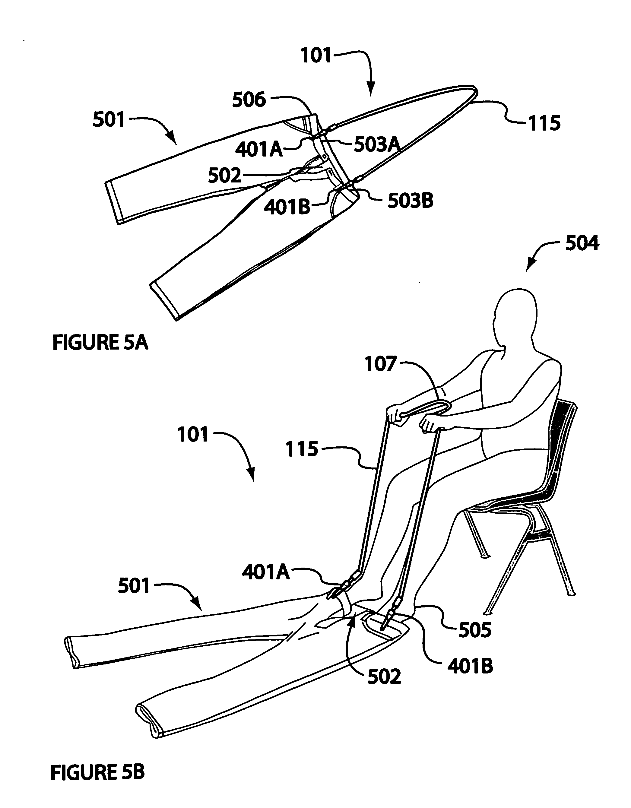
[0041] The function of the dressing aid 101 is simply illustrated in reference to FIG. 5A and FIG. 5B. First the dressing aid 101 is attached by the grip devices 401A/B to the waistband 506 of the garment 501. Attachment should be near the fly 502 or front opening of the garment. As seen in FIG. 5A, the garment 501 (pants as illustrated) is viewed face-up. The first member of the first pair of grip devices 401A is attached to the right side 503A of the waist band 506, near the fly 502, and the second member of the first pair of grip devices 401B is attached to the left side 503B of the pants near the fly 502 on the waist band 506. (Designation of which gripe device is attached to the left or right side of the garment is arbitrary and can be reversed without changing the scope or intent of the invention). The length of connective material 115 extends upward with the center point somewhat centered on the garment.
[0042] As illustrated, the seated individual 504 has attached the device 101 to the garment and positioned the garment on the floor, face up. With feet 505 positioned appropriately at the top of the left and right leg and the length of connective material 115 grasped in both hands with the mid-point 107 generally centered, the length of connective material 115 is pulled upward, and the pants are pulled up over the lower legs and thighs, by raising slightly, and continuing the upward pull, the pants are moved to the hips where they can be adjusted and fastened. Donning the garment requires only minimal bending of the back or knees.
[0043] A hook (or clip) device 120 may be positioned at the mid-point 107 of the length of connective material 115. The hook (or clamp) 120 device may be attached to a shirt of blouse pocket or button hole to hold the connective material and attached garment in position and free one or both hands of the individual to fasten the waistband and disconnect the two gripe devices from the garment. The hook (or clip) is attached such that it will pull free of the garment in the event of a moderate tug or jerk to minimize the risk of entanglement with the dressing aid.
Example 2
[0044] The dressing aid 101 of FIG. 1 is modified in this second example as illustrated in FIG. 2. The members of a second pair of grip devices 401C and 401D are connected respectively to the first half length 109 and the second half length ill of the length of connective material 115 by the first and second segments of the connecting material 201A and 201B, respectively. the first end of each segment of connecting material is attached to an arm of one of the members of the second pair of gripe devices 401C and 401D, and the second end of each segment of connecting material is attached to the first 109 or second 111 half length of the length of connecting material 115 at a point such that the members of the first pair of grip devices 401A/B extend about the length 202 of the grip device below the members of the second pair of grip devices.
[0045] Functionally, the device is comparable to the function of the device as described for FIG. 1, except as the first step the first and second members of the second pair of grips are attached to or near the waist band of an undergarment generally as described for FIG. 1, and the first and second members of the first pair of grips are attached to the outer garment as previously described. In this manner, the undergarment is positioned inside in relation to the garment attached to the members of the first pair of grips.
[0046] Following the method described in the first figure, as the length of connective material 115 is pulled upward, the undergarment moves upward and can be positioned and the first and second members of the second grips released and removed from the undergarment and then the pants also positioned as desired and previously described.
[0047] The device described in Example 1 employing only a single pair of gripe devices is also adapted to donning inner and outer lower garments simultaneously. Unless one garment is unusually heavy or cumbersome, position the inner garment in the outer garment with the waist bands aligned along their top lines and the fly or other opening aligned. Grasp the left and the right side of each garment as with only a single garment, and before placing them on the floor to be donned, straighten the inner and outer garment legs to ensure that they are aligned and don the garment as previously described. The optional hook (or clamp) device 120 may be used as previously described.
Example 3
[0048] Note in the following, reference numbers indicating pieces, parts, and elements described in FIGS. 1,2 and 4 are retained in all other figures when the piece, part, element, or function is identical to that previously described and indicated on one of the above referenced figures. This includes the positioning and use of the optional hook (or clamp 120) device as previously described.
[0049] FIG. 3 illustrates an alternative hand piece 301 basic dressing aid 101 previously described. The hand piece 301 comprises a single tube element 303. The single tube element 303 has a length 305, a diameter 307, and an open longitudinal chase 331 defined and limited by the tube wall 313.
[0050] The tube element varies in length from about approximately 4 inches to 18 inches (10 cm to 46 cm) preferably from 6 to 10 inches (15 to 25 cm). The diameter of the tube varies from 1 to 3 inches (2.5 to 7.5 cm). Note, the above length and diameter dimension are exemplary and do not constitute limitations on the invention. The tube may be fabricated from any rigid, light weight material including metals. plastics, and composite materials.
[0051] A top opening 315 traverses the tube wall 313 at the mid-point of the upper longitudinal line 309 of the single tube 303. The first bottom opening 317 and the second bottom opening 319 traverse the wall 313 at a distance respectively from the first end of the single tube 327 and the second end of the single tube 329 on the lower longitudinal line 311. The lower longitudinal line 311 is diametrically opposite the upper longitudinal line 309 on the outer surface of the single tube 303. Both lines are for reference only with respect to positioning or locating the top opening 315 and the first and second bottom openings 317 and 319, respectively. The diameter of the top opening and of the first and second bottom openings is variable. The top opening must be large enough to allow free simultaneous passage of both the first half 109 and the second half 111 of the cord material, and the first and second bottom openings must allow free passage respectively of the first half 109 or the second half 111 of the cord material.
[0052] A length of the length of connective material 115 is positioned within the open chase 331 of the single tube 303 such that the end 333 of the first half-length extends downward through the first bottom opening 317, and the end of the second half-length 335 extends downward through the second bottom opening 319. The midpoint 107 extends upward through the top opening 315. The first half-length 109 and the second half-length 111 are joined for a short distance at a point below the midpoint 107 to form a loop 323. A hook element 120 may be threaded onto the cord material 115 inside the loop 323. A mechanical stop device 350 allows the passage of the cord material to be controlled as previously described.
[0053] Members of the first pair of grip devices 401A and 401B are positioned as previously illustrated and discussed with respect to FIG. 1. Members of a second pair of grip devices may be attached to the first and second half lengths 109 and 111 respectively of the length of connective material as described in FIG. 2 without changing the scope or intent of the invention. In terms of application, the single tube is used in a manner slightly different from that described for Example 1 and Example 2. The device is connected to the garment as described and the garment attached as in Example 1 and Example 2. The single tube 303 is held by one hand at about hip height, or otherwise on the lap. The garment is pulled (drawn) up, over the feet and lower legs by pulling the length of material 115 upward, through the single tube 303. When the garment reaches mid-leg, it is grasped as previously described, and dressing is completed as described.
[0054] The cord material and grip device can be folded into the open chase or core of the single tube and caps positioned of the first end 327 and second end 329 of the single tube for convenient storage.
Example 4
[0055] In additional configurations and modes, the dressing aid comprises a spreader element 601 and a length of connective material 115. In one alternative configuration, the first and second ends 103 and 105, respectively, of the length of connective material 115 are connected to and contiguous with a first 617A and a second 617B grip connectors. The free end of the first 617A and second 617B grip connectors is attached respectively to the first 401A and second 401B grip devices. In an alternate configuration, the first 617A and second 617B grip connectors are separate from (not contiguous with) the first 103 and second 105 ends of the length of connective material 115. The first and second ends of the length of connective material are connected directly to the spreader device. Each members of a pair of grip devices 401A and 401B is attached to one end of either the first 617A or second 617B grip connectors, and the opposite end of each of the grip connectors is connected directly to the spreader element. In one configuration, the members of the pair of grip devices 401A and 401B are attached directly to the spreader element and no grip connectors are required.
[0056] In one specific mode, FIG. 6A, the spreader element 601 comprises a spreader bar body 602 with a length 603 that varies, by way of illustration, not limitation, from 12 to 16 inches (30 to 40 cm), with a height 604 varying, but not limited to about 0.5 to 1.5 inches (1.25 to 3.75 cm) and a width 605 varying by way of example but not limitation from 1 to 2.5 inches (2.5 to 6.3 cm) and further comprising a top face 606, a bottom face 607, a front face 608, and a back face 609. The cross section configuration of the spreader bar as illustrated is a rectangle 610; one skilled in the art recognizes that the cross section configuration could be a variety of shapes from a square or other rectangle with rounded edges to an oval to a circle, in which case the bar might better be described as a rod, tube, or cylinder. Such variations in configuration are anticipated by the invention and included by reference. In practice, even the rod, tube, or cylinder configuration may be described as having a top bottom, and first and second side faces, although they are not precisely defined, they can be described in simple geometric terms not here included.
[0057] In one mode illustrated in FIG. 6A, the first 613A and second 613B ends of the length of connective material 115 traverse the bar through its body 602, from its front 608 to its back 609 face. Connection chases 612A and 612B are positioned approximately 1 inch (2.5 cm) respectively from the first end 614A and second end 614B of the bar body 602. The ends of the first 613A and second 613B grip connectors are attached to the corresponding grip devices 401A and 401B. The grip connectors are contiguous with the corresponding ends of the length of connective material 115, and traverse the bar 602 through connector chases 612A and 612B. The length of the grip connector 615 varies, by way of example, not limitation, from 1 to 3 inches (2.5 to 7.5 cm, preferably from 1.5 to 2 inches (3.8 to 5 cm). In addition to prevent the length of connection material from being pulled back, through the bar body 602, the length of connection material is secured with an adhesive in each connection chase 612A and 612B.
[0058] In an alternative mode illustrated in FIG. 6B, the first 613A and second 613B ends of the length of connective material are secured and anchored in the corresponding connector chases 612A and 612B at anchor points 619A and 619B by an adhesive material. The length of connective material does not traverse the spreader bar, but passed through its front face 608. The grip devices 401A and 401B are connected to the corresponding grip connectors 617A and 617B at one end as previously described. The opposite end of each grip connector 617A and 617B is positioned at and secured to a connection point receptacle 620A and 620B, respectively. Distances, dimensions and materials are comparable for those described for FIG. 6A.
[0059] As illustrated in FIGS. 6A and 6B, the cross section shape 610 of the spreader is rectangular. One of average skill in the art recognizes that the spreader bar may assume any of a variety of cross section shapes, such as, but not limited to any rectangular configuration with rounded edges, a round, or an oval shape, without altering or expanding the scope, intent, or purpose of the invention, and the faces and dimensions described in the above example are readily modified to fit such shapes all of which are anticipated by the claimed invention. In one preferred, practical mode, the spreader bar is a tube, cylinder, or rod in cross section configuration.
[0060] The spreader bar body 602 may be fabricated from a variety of natural or synthetic materials, including wood, plastics, light metals, and alloys. Preference may be giver to light weight materials that are readily sterilized. Regardless of cross section shape, the material may be solid or hollow. If it is hollow, open ends are generally secured with an appropriate cap or plug. Preferred embodiments are fabricated from non-porous materials that may readily be sanitized.
[0061] Use of the dressing aid with a spreader bar is similar to that described for the basic aid described in FIG. 1, but the device and its function are markedly different from the basic dressing aid in simplicity and ease of use. As illustrated in FIG. 6C, the garment 501 (pants as illustrated) is positioned with the waist on the lap of the user with the fly 502 open. The first member 401A of the pair of grip devices is attached to the right side 503A of the waistband 506 of the garment 501, and the second member 401B is attached to the left side 503B. The connection of the grip devices 401A and 401B to the garment 501 and to the bar body 602 by the first and second grip connectors 617A and 617B holds the fly 502 open and prevents it from folding over and closing. The garment is placed fly up on the floor in front of the user. By pulling the length of connective material 115 slightly upward and inward, the feet can be positioned under the spreader bar and in the waist area of the garment oriented to the legs. The spreader bar holds the fly and waist open and pulling the spreader over the feet helps orient the garment to complete dressing. When the spreader bar has been drawn up, over the knees, the use may grasp the spreader bar and pull the garment to the waist, stand disconnect the grip device, grasp the garment, stand and complete donning the garment.
[0062] As illustrated and described above, the spreader bar dressing aid is adapted to donning a single garment; however, it is anticipated that a second pair of grip devices (not illustrated) may be connected to the spreader bar as described for FIG. 9C with respect to the basic dressing aid as illustrated in FIG. 1, such that both under and outer garments may be donned simultaneously and conveniently with the spreader bar dressing aid.
Example 5
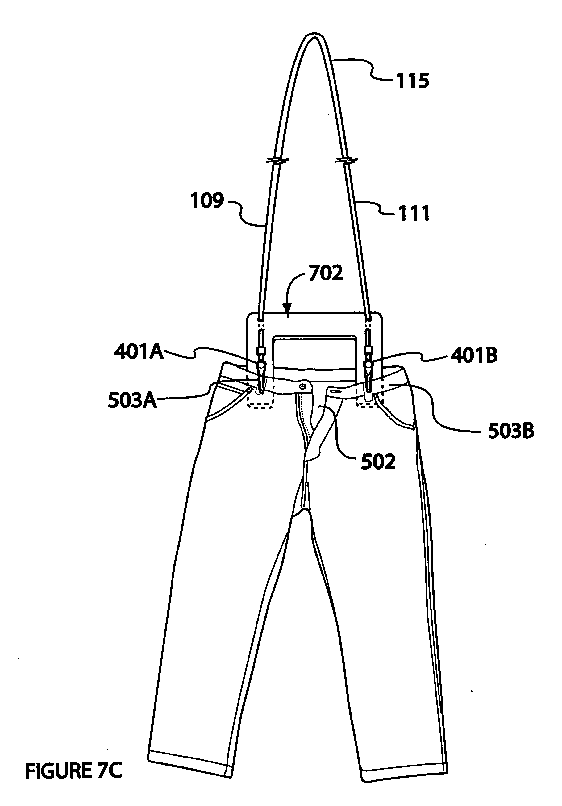
[0063] In an additional best mode, FIG. 7A, the spreader element 601 comprises a flat plate 702, somewhat in the shape of an inverted block letter U with a base 703, a first arm 704A and a second arm 704B, a top surface 705A, and a bottom surface 705B. The width of the base 706A varies from 1 to 4, preferably 1.5 to 2.5 inches (2.5 to 10, preferably 2.50 to 3.75 cm), by way of illustration, not limitation, and the overall length of the base 706B varies from 12 to 16 inches (33 to 40 cm), preferably from 9 to 15 inches (22 to 38 cm). The length of the arms 707 ranges by way of illustration, not limitation from 8 to 10 inches (20 to 25 cm), and the width of the arms 718 varies from 1 to 3 inches (2.5 to 7.5 cm) for example. The thickness of the plate 708 varies from approximately 0.5 inch to 1.0 inch (1.25 to 2.50 cm), primarily based on the material from which the plate 702 is fabricated. Suitable materials include, but are not limited to wood, plastics, light metals and alloys, and stainless steel. As for the bar spreader, ease of sanitation may be a consideration in selecting an appropriate material.
[0064] As in the spreader bar example, this mode anticipates two configurations. Both configurations comprise a length of connective material 115 with a first end 613A and a second end 613B. Members of a pair of grip devices 401A and 401B are secured to the first and to the second 613A and 613B end of the length of connective material 115. The total length of the length of connector material varies from less than 6 to 9 feet (less than 2 to 3 m) with a functional length 709 of one half the total length.
[0065] In one configuration, FIG. 7A, a first pair of connector chases 710A and 710B is formed through the U-base 703 approximately 0.5 to 1.0 inch (1.25 to 2.50 cm) from the corresponding edge 711A and 711B of the U-base 703. A second pair of connector chases 712A and 712B is similarly formed 3 or more inches (7.5 or more cm) from the corresponding tip 713A and 713B of each arm 704A and 7048.
[0066] In this configuration, the first end of the length of connective material 613A is passed from the top 705A of the U-base 703 through the first member of the first pair of connector chase 710A, traverses the bottom 705B of the first arm 704A and passes upward through the first member of the second pair of connector chase 712A. The length of connective material 613A extends from the second connector chase 712A and comprises the first grip connector 714A to which the first member of a pair of grip devises 401A is securely attached. In the same manner, the second end 613B of the length of connective material 115 and a the second member 401B of a pair of grip devices is positioned on the second arm 704B. The length of the grip connector 715A and 715B varies from about 1 to 2 inches (about 2.5 to 5.0 cm) and, when connected to a grip device, the distal tip 716A and 716B of that grip device is a minimum of 1 inch (2.5 cm), preferably 2.5 inches (6.3 cm) from the tip 713A of the first arm 704A. The length of connective material is secured in the in the first 710A and 710B and second 712A and 712B connector chases with an adhesive appropriate for the material from which the plate 702 is fabricated as such adhesives are commonly know to those skilled in the art and readily available in commercial channels.
[0067] FIG. 7B illustrates a second configuration with a flat plate 702 spreader with gripe devices 401A and 401B secured directly at their corresponding second connector chase 712A and 712B, and the first and second ends 613A and 613B of the length of connective material 115, respectively, are secured directly in the corresponding first connector chases 710A and 710B.
[0068] The first and second grip devises 401A and 401B are attached directly to the top 705 of the first and second arms 704A and 704B respectively, at a point approximately 1.5 to 3.0 inches (3.75 to 7.50 cm) from the ends 713A and 713B from the first 704A and second 704B arm.
[0069] The use of the arm spreader dressing aid is similar to the use of the previously described bar spreader dressing aid. With the user seated, the garment is placed face up, with the fly open 622, on the user's lap. With the plate top surface 705A facing up, the arms 704A and 704B are positioned in the waist/upper leg openings of the garment, oriented with the first arm 704A positioned towards the left leg and the second arm 704B towards the right leg of the garment. The first member of the pair of grip devices 401A is connected to the left side 503A of the waist, and the second member of the pair to the right side 503B. The base 702 of the U spreader holds the fly 622 open and the arms separate the legs of the garment. With the garment attached to the two members of the pair of grip devices, the garment is pulled slightly upward and inward (towards he user). This uniformly lifts the waist of the garment and separates the legs (or left and right sides of the garment. Each foot is positioned under the spreader element 701 and the spreader element 701 is lifted slightly and pulled over the feet and pulled innards and upwards over the calves and thighs. The length of connector material may be held in one hand, or connected by the attached hook to a shirt, and the spreader element is disconnected with the length of connector material placed safely away from the feet and legs to avoid tripping. As described for other examples of dressing aids, the user grasps the spreader element or length of connection material and pulls the garment over the hips and closes the fly (or other opening in the waist to complete dressing.
[0070] As illustrated, the device has a single pair of grip devices. The U spreader device is adapted to two pairs of grip devices so that under and outer garments can be donned simultaneously, as with other modes herein described.
[0071] One skilled in the art recognizes that reference to the left and right side with respect to the parts of the device and garment are for convenience of explanation and illustration and that the sides may be reversed without changing the scope or intent of the invention.
Example 6
[0072] FIGS. 8A,8B, and 8C illustrate an additional best mode of the dressing aid 801 in which the body of the devise 801 comprises a single length 802 of web material from 0.5 to 1.25 inches (1.3 to 3.8 cm) wide 802A with contiguous, equal half lengths 805A and 805B each approximately 4 feet (1.2 m) in length 805C (total length approximately 2.4 m).
[0073] The first member 804A of a pair of grip devices is attached to the first end 806A of the single length of web material 802, and the second member 804B of the pair of grip devices is attached to the second end 806B of the single length of web material 802.
[0074] The grip device may be attached to the ends 806A/B of web material 802 in a variety of manners, all of which are anticipated by the invention. Commonly, the grip device includes a connective structure or means. In a preferred configuration illustrated in FIGS. 8B and 8C, the proximal end 824 of the grip devices 804A/B is a loop, ring, or mechanical clamp 807 designed to engage the end 806A/B of the single length of web material 802. As shown in FIG. 8B and FIG. 8C, by way of illustration, not limitation, a short section near each end 806A/B of each half length 805A/B is folded back on corresponding half section to form a short loop 808 that engages the ring (or other structure) 807. The end may be attached by sewing, mechanical connectors (rivets or the like), or adhesives.
[0075] A fixed spacer unit 809 (FIG. 8A and FIG. 8B) separates holds the first 806A and second 806B ends of the single length of web material apart to facilitate use of the dressing aid. The fixed spacer unit 809 comprises a cylinder 810 with a length 812A and diameter 812B and a first end 813A and a second end 813B. The length of the cylinder 812A varies from approximately 10 to 15 inches, preferably 12 inches (25 to 38, preferably 30 cm). The diameter varies from 0.5 to 1.5 inches, preferably 1.0 inches (1.3 to 3.9 cm, preferably 2.5 cm). The first 813A and second 813B ends are closed with corresponding first 814A and second 814B closure flaps. For illustrative purposes, FIG. 8B shows the first closing flap 814A in position closing the first end 806A, and the second closing flap 814B attached at one point and with the second end 813B open. The flaps can be secured by adhesive straps (velcro) or sewn, as well as zippers or similar means understood by those skilled in the art.
[0076] A spacer element 818 is positioned in the cylinder 810. FIG. 8B shows the spacer element 818 partially inserted into the cylinder 810 through the second end 813B of the cylinder, with the first end 813A closed. The length 819 of the spacer element and diameter 820 of the spacer element are nominally equal to the corresponding length and diameter of the cylinder, reduced so that the spacer element may readily be positioned in the cylinder unit 810.
[0077] The spacer element may be manufactured from a variety of rigid, light weight tubular materials. PVC pipe is preferred because of its availability and range of diameters available; light metal and even wood is acceptable, noting that wood is more difficult to sterilize and therefore not preferred. One skilled in the art recognizes that the cross section configuration of the spacer element may be oval, rectangular or square, so long as corners are smoothed to avoid injuries in using the device.
[0078] The spacer unit is attached to the first 803A and the second half 803B of the single length of web material 802 such that the space 821 between bottom edge 817A of the cylinder and the tip of the corresponding grip device 817B is 1.5 to 2.5, preferably 2.0 inches (3.8 to 6.3, preferably 2.5 cm). This distance is preferably no more than twice the length of the grip device. See FIG. 8C.
[0079] FIG. 8B shows the fixed space unit 809 with the space element 818 partially inserted into the cylinder 809 as sen in the cut-away sections 821, with the cylinder 810 connected to the first 803A and second half 803B of the single length of web material 802 respectively near the first 813A and second 813B ends of the cylinder 810. The first closing flap 814A is closed, and the second closing flap 814B is attached at one point 822 and open to allow insertion of the spacer element 818.
[0080] The dressing aid 801 of this Example 6 is attached to and used in a manner similar to attachment and use illustrated, for example, by FIGS. 5A and 5B.
[0081] For convenience, the garment is assumed to be pants; one of average skill recognizes the same steps apply to other garments without amplification. With the user seated, the garment is placed face up with the fly open on the users lap. One member of the pair of grip devices is attached to the waist band of the first side of the fly and the second member of the pair of grip devices is similarly attached to the waist band on the second side of the fly such that the spacer separates the two grip devices by a distance of essentially the length of the spacer element 812A. The garment and attached dressing device are placed flat on the floor, face up in front of the seated user.
[0082] Slightly raising both halves of the single length of web lifts and the garment, with the spacer element holding the fly open. The feet are positioned in the garment and the spacer element is pulled upward, pulling the garment up to or above the knees. At this point, the user can grasp the spacer element with one hand (or continue to hold the device by the web material) and stand to pull the garment to the hips/waist line. The generally, grips are disconnected while the user is seated and the fly is ready to closed. Prior to complete adjusting the garment in complete dressing, the user should gather and store the device, with care exercised to ensure that the single length of web material has been stored safely and does not present tripping or otherwise injuring the user. To ensure that the feet are extended through the garment's legs, each cuff may be folded upward until dressing is completed. Also, prior to disconnecting the dressing aid from the garment, a soft hook connected to the spacer may be loosely connected to a shirt to secure the garment in place until the fly is closed and secured.
[0083] The preceding examples may be divided and recombined to yield additional combinations all of which are anticipated by the invention, and as a result, the following claims should be accorded the broadest construction and not be restricted or limited by any single example.
* * * * *
References
D00000
D00001
D00002
D00003
D00004
D00005
D00006
D00007
D00008
D00009
D00010
D00011
D00012

D00013

D00014

XML
uspto.report is an independent third-party trademark research tool that is not affiliated, endorsed, or sponsored by the United States Patent and Trademark Office (USPTO) or any other governmental organization. The information provided by uspto.report is based on publicly available data at the time of writing and is intended for informational purposes only.
While we strive to provide accurate and up-to-date information, we do not guarantee the accuracy, completeness, reliability, or suitability of the information displayed on this site. The use of this site is at your own risk. Any reliance you place on such information is therefore strictly at your own risk.
All official trademark data, including owner information, should be verified by visiting the official USPTO website at www.uspto.gov. This site is not intended to replace professional legal advice and should not be used as a substitute for consulting with a legal professional who is knowledgeable about trademark law.