Paint Can Strap And Holder
MACDONALD; Vance ; et al.
U.S. patent application number 13/166923 was filed with the patent office on 2011-12-29 for paint can strap and holder. This patent application is currently assigned to KOVRD PRODUCTS INC.. Invention is credited to Benjamin LEONARD, Vance MACDONALD.
| Application Number | 20110315700 13/166923 |
| Document ID | / |
| Family ID | 45351567 |
| Filed Date | 2011-12-29 |


View All Diagrams
| United States Patent Application | 20110315700 |
| Kind Code | A1 |
| MACDONALD; Vance ; et al. | December 29, 2011 |
PAINT CAN STRAP AND HOLDER
Abstract
Paint can straps and holders releasably attachable to a paint can are provided, such that at least one of fingers, a hand, forearm, and an arm can be inserted between a strap portion and the paint can, and along a longitudinal axis of the paint can, to leverage the paint can. The paint can holder includes a strap that is releasably attachable to the paint can. The strap can be attached to a harness, which is releasably attachable to the paint can. The harness can include a paint brush holder which can also be provided independent of the harness.
| Inventors: | MACDONALD; Vance; (Calgary, CA) ; LEONARD; Benjamin; (Calgary, CA) |
| Assignee: | KOVRD PRODUCTS INC. Calgary CA |
| Family ID: | 45351567 |
| Appl. No.: | 13/166923 |
| Filed: | June 23, 2011 |
Related U.S. Patent Documents
| Application Number | Filing Date | Patent Number | ||
|---|---|---|---|---|
| 61357572 | Jun 23, 2010 | |||
| 61423632 | Dec 16, 2010 | |||
| 61449298 | Mar 4, 2011 | |||
| Current U.S. Class: | 220/754 |
| Current CPC Class: | B44D 3/14 20130101 |
| Class at Publication: | 220/754 |
| International Class: | B65D 25/00 20060101 B65D025/00 |
Claims
1. A paint can strap, comprising: a strap portion comprising a first end and a second end distal said first end. a first attachment portion at said first end, and a second attachment portion at said second end, each of said first attachment portion and said second attachment portion enabled for releasable attachment to a handle of a paint can such that at least one of a hand and an arm can be inserted between said strap portion and said paint can, and along a longitudinal axis of said paint can, to leverage said paint can.
2. The paint can strap of claim 1, wherein when said paint can strap is attached to said handle by said first attachment portion and said second attachment portion, said strap portion extends along a circumference of said paint can.
3. The paint can strap of claim 1, wherein each of said first attachment portion and said second attachment portion comprises one or more of a carabineer, a strap, and a respective hook portion for releasably hooking said strap portion to said handle.
4. The paint can strap of claim 3, wherein each said respective hook portion extends towards said strap portion from a respective end of each said first attachment portion and said second attachment portion, and wherein a gap is formed between each said respective hook portion and a respective body portion of each said first attachment portion and said second attachment portion, said gap enabled to receive said handle of said paint can.
5. The paint can strap of 4, wherein said gap is in a range of approximately 0.05 inches to approximately 0.75 inches
6. The paint can strap of claim 4, wherein each said respective hook portion comprises a respective protrusion that protrudes towards a respective body of each said first attachment portion and said second attachment portion, said protrusion for holding said handle between each said respective hook portion and said respective body.
7. The paint can strap of claim 3, wherein each respective hook portion is enabled for releasably hooking said strap portion to said handle in at least a resting position and a use position, such that in said resting position an edge of said strap portion rests against a wall of said paint can, and in said use position, said strap portion extends along a circumference of said paint can.
8. The paint can strap of claim 1, wherein said strap portion is integral with said first attachment portion and said second attachment portion.
9. The paint can strap of claim 1, wherein said each of said first attachment portion and said second attachment portion are releasably attached to respectively said first end and said second end.
10. The paint can strap of claim 9, wherein said strap portion is adjustable at each of said first attachment portion and said second attachment portion.
11. The paint can strap of claim 10, wherein each of said first attachment portion and said second attachment portion comprises at least one opening for receiving a respective end of said strap portion.
12. The paint can strap of claim 11, wherein said strap portion comprises at least one ridge, and wherein said at least one ridge engages said at least one opening, holding said strap portion there in.
13. The paint can strap of claim 12, wherein said strap portion comprises a plurality of ridges, and wherein said at least one ridge engages said at least opening, holding said strap portion there in, said strap portion being adjustable by selecting a given ridge for engaging said at least one opening.
14. The paint can strap of claim 13, wherein said at least one opening comprises a plurality of adjacent slots such that said strap portion can be woven through said adjacent slots, at least one of said plurality of ridges engaging at least one of said plurality of slots.
15. The paint can strap of claim 1, wherein each of said first attachment portion and said second attachment portion comprises a paint can handle attachment end and a strap attachment end distal said paint can handle attachment end.
16. The paint can strap of claim 15, wherein each of said first attachment portion and said second attachment portion further comprises: respective handle attachment apparatus at said paint can handle attachment end, each said respective handle attachment apparatus for releasably attaching said handle. and a strap attachment apparatus for attaching said strap portion to each of said first attachment portion and said second attachment portion.
17. The paint can strap of claim 1, wherein at least one of said first attachment portion and said second attachment portion is enabled to hang said paint can strap from a hook to store said paint can strap.
18. The paint can strap of claim 1, wherein a distance from distal ends of each of said first attachment portion and said second attachment portion is in a range of approximately 10 inches to approximately 20 inches.
19. The paint brush strap of claim 1, wherein at least one of said strap portion, said first attachment portion, and said second attachment portion comprises at least one of a plastic, santoprene, rubber, TPU (Thermal Polyurethane), polyurethane, Sarlink, elastomer, polypropylene, polyethylene, ABS (acrylonitrile-butadiene-styrene) PC (polycarbonate), PBT (polybutylene terephthalate), silicone, an injection molded material, and a material cast from a metal die.
20. A paint can strap, comprising: an attachment portion for attaching said paint can strap to a handle of a paint can approximately midway along said handle; and a sleeve portion attached to said attachment portion, said sleeve portion enabled to receive at least one of at least a portion of a hand and an arm inserted therein, along a longitudinal axis of said paint can, such that leverage can be applied to said paint can via said handle.
Description
CROSS-REFERENCE TO RELATED APPLICATIONS
[0001] The specification claims priority from U.S. Provisional Application 61/357,572 filed Jun. 23, 2010, U.S. Provisional Application 61/423,362 filed Dec. 16, 2010 and U.S. Provisional Application 61/449,298 filed Mar. 4, 2011, all which are incorporated by reference.
FIELD
[0002] The specification relates generally to paint accessories, and specifically to paint can straps and holders.
BACKGROUND
[0003] Using a paint can as a cut can (i.e. for painting directly from the paint can) can be tiring for a painter as holding the paint can by the handle can be uncomfortable and even painful.
BRIEF DESCRIPTIONS OF THE DRAWINGS
[0004] For a better understanding of the various embodiments described herein and to show more clearly how they may be carried into effect, reference will now be made, by way of example only, to the accompanying drawings in which:
[0005] FIG. 1 depicts a front perspective view of a paint can holder releasably attached to paint can, according to non-limiting implementations.
[0006] FIG. 2 depicts a front perspective of a paint can holder, according to non-limiting implementations.
[0007] FIG. 3 depicts a rear perspective view of a paint can holder, according to non-limiting implementations.
[0008] FIG. 4 depicts a left side view of a paint can holder, according to non-limiting implementations.
[0009] FIG. 5 depicts a front view of a paint can holder, according to non-limiting implementations.
[0010] FIG. 6 depicts a right side view of a paint can holder, according to non-limiting implementations.
[0011] FIG. 7 depicts a rear side view of a paint can holder, according to non-limiting implementations.
[0012] FIG. 8 depicts a plan view of a paint can holder, according to non-limiting implementations, and
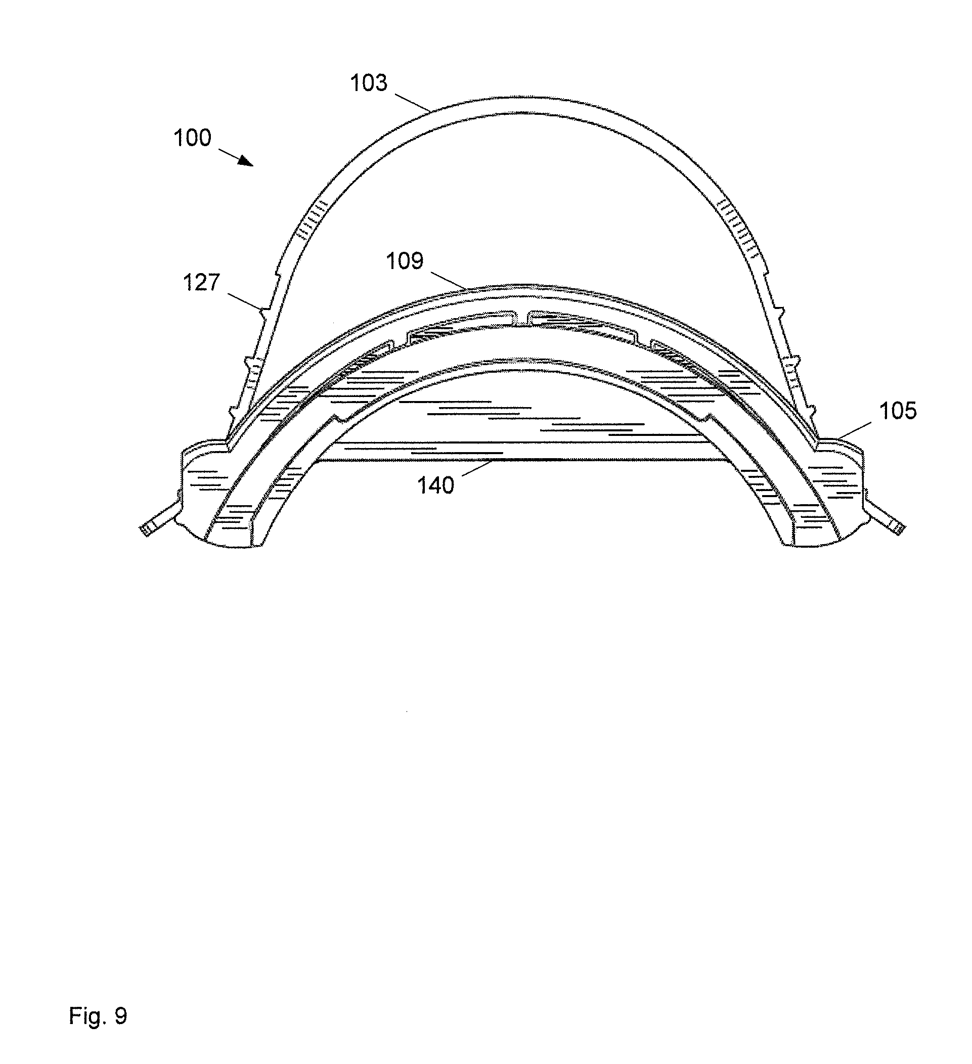
[0013] FIG. 9 depicts a bottom view of a paint can holder, according to non-limiting implementations.
[0014] FIG. 10 depicts a perspective front view of a paint can holder, according to non-limiting implementations.
[0015] FIG. 11 depicts a perspective front view of a harness of a paint can holder, according to non-limiting implementations.
[0016] FIG. 12 depicts a perspective side view of a harness of a paint can holder, according to non-limiting implementations.
[0017] FIG. 13 depicts a front side view of a strap attachable to the harness of FIG. 11, according to non-limiting implementations.
[0018] FIG. 14 depicts a right side view of a paint can holder releasably attached to paint can, according to non-limiting implementations.
[0019] FIG. 15 depicts a left side view of a paint can holder releasably attached to paint can, according to non-limiting implementations.
[0020] FIG. 16 depicts a front side view of a paint can holder releasably attached to paint can, according to non-limiting implementations.
[0021] FIG. 17 depicts a top side view of a paint can holder releasably attached to paint can, according to non-limiting implementations.
[0022] FIG. 18 depicts a side view of the strap of FIG. 13, according to non-limiting implementations.
[0023] FIG. 19 depicts a perspective view of a paint can holder attached to a paint can, according to non-limiting implementations.
[0024] FIG. 20A depicts the paint can holder of FIG. 19, according to non-limiting implementations.
[0025] FIG. 20B depicts a paint can holder, according to non-limiting implementations.
[0026] FIGS. 21A, 21B, 22A, 22B, and 23 depict a paint can holder according to non-limiting implementations.
[0027] FIG. 24 depicts a perspective view of a paint can holder comprising a paint brush holder, according to non-limiting implementations.
[0028] FIGS. 25 and 26 depict top views of paint brush holders, according to non-limiting implementations.
[0029] FIG. 27 depicts a perspective view of a paint can holder comprising a paint brush holder, attached to a paint can, according to non-limiting implementations.
[0030] FIG. 28 depicts a bottom perspective view of a paint can holder comprising a paint brush holder, attached to a paint can, according to non-limiting implementations.
[0031] FIG. 29A depicts a bottom view of an integral piece comprising a paint brush holder and a gasket portion, according to non-limiting implementations.
[0032] FIG. 29B depicts a top view of an integral piece comprising a paint brush holder and a gasket portion, according to non-limiting implementations.
[0033] FIG. 29C depicts a side view of an integral piece comprising a paint brush holder and a gasket portion, according to non-limiting implementations.
[0034] FIG. 30 depicts a perspective view of a paint brush holder, attached to a paint can, according to non-limiting implementations.
[0035] FIG. 31 depicts a side view of a paint brush holder, according to non-limiting implementations.
[0036] FIG. 32A depicts a perspective view of a paint can holder comprising a paint brush holder holding a paint brush, attached to a paint can, according to non-limiting implementations.
[0037] FIG. 32B depicts a perspective cutaway view of a paint can holder comprising a paint brush holder holding a paint brush, attached to a paint can, according to non-limiting implementations.
[0038] FIGS. 33A, 33B, and 33C depict a perspective view of a paint can holder comprising a paint brush holder holding a paint brush in different respective positions, according to non-limiting implementations.
[0039] FIG. 34A depicts a perspective view of a paint can holder comprising a paint brush holder holding a paint brush, attached to a paint can, the paint brush holder in a first position, according to non-limiting implementations.
[0040] FIG. 34C depicts a perspective view of a reversible integral piece comprising a paint brush holder and a gasket portion, according to non-limiting implementations.
[0041] FIG. 34C depicts a perspective view of a paint can holder comprising a paint brush holder holding a paint brush, attached to a paint can, the paint brush holder in a second position, according to non-limiting implementations.
[0042] FIG. 35 depicts a perspective view of a paint can holder comprising a paint brush holder, according to non-limiting implementations.
[0043] FIG. 36A depicts a bottom view of an integral piece comprising a paint brush holder and a gasket portion, according to non-limiting implementations.
[0044] FIG. 36B depicts a top view of an integral piece comprising a paint brush holder and a gasket portion, according to non-limiting implementations.
[0045] FIG. 36C depicts a side view of an integral piece comprising a paint brush holder and a gasket portion, according to non-limiting implementations.
[0046] FIG. 37A depicts a top view of a paint brush holder, according to non-limiting implementations.
[0047] FIG. 37B depicts a bottom view of a paint brush holder, according to non-limiting implementations.
[0048] FIG. 38 depicts a perspective view of a paint can strap releasably attachable to a paint can, according to non-limiting implementations.
[0049] FIG. 39 depicts an exploded perspective view of the paint can strap of FIG. 38, according to non-limiting implementations.
[0050] FIG. 40 depicts a perspective view of a paint can strap releasably attached to a paint can, according to non-limiting implementations.
[0051] FIG. 41 depicts a perspective view of a paint can strap releasably attached to a handle of a paint can, according to non-limiting implementations.
[0052] FIG. 42A depicts a front perspective view of an attachment portion of the paint can strap of FIG. 38, according to non-limiting implementations.
[0053] FIG. 42B depicts a side view of the attachment portion of FIG. 42A, according to non-limiting implementations.
[0054] FIG. 42C depicts a rear perspective view of the attachment portion of FIG. 42A, according to non-limiting implementations.
[0055] FIG. 43A depicts a perspective view of a paint can strap releasably attached to a paint can in an in-use position, according to non-limiting implementations.
[0056] FIG. 43B depicts a perspective view of a paint can strap releasably attached to a paint can in an intermediate position, according to non-limiting implementations.
[0057] FIG. 43C depicts a perspective view of a paint can strap releasably attached to a paint can in a rest position, according to non-limiting implementations.
[0058] FIG. 44 depicts a front perspective view of the attachment portion of FIG. 42A attached to an end of a strap portion of the paint can strap of FIG. 38, according to non-limiting implementations.
[0059] FIG. 45 depicts a rear perspective view of the attachment portion of FIG. 42A attached to an end of a strap portion of the paint can strap of FIG. 38, according to non-limiting implementations.
[0060] FIG. 46 depicts a side perspective view of the attachment portion of FIG. 42A attached to an end of a strap portion of the paint can strap of FIG. 38, according to non-limiting implementations.
[0061] FIG. 47A depicts a front perspective view of the attachment portion of FIG. 42A attached to a paint can handle in a first position, according to non-limiting implementations.
[0062] FIG. 47B depicts a front perspective view of the attachment portion of FIG. 42A attached to a paint can handle in a second position, according to non-limiting implementations.
[0063] FIG. 48A depicts a perspective view of a paint can strap attached to a paint can, the paint can strap extended in a first position, according to non-limiting implementations.
[0064] FIG. 48B depicts a perspective view of a paint can strap attached to a paint can, the paint can strap extended in a second position, according to non-limiting implementations.
[0065] FIG. 49A depicts a front perspective view of an attachment portion of the paint can strap of FIG. 43A, according to non-limiting implementations.
[0066] FIG. 50 depicts a perspective view of a paint can strap attached to a paint can, according to non-limiting implementations.
[0067] FIG. 51 depicts a perspective view of a paint can strap attached to a paint can, according to non-limiting implementations.
SUMMARY
[0068] An aspect of the specification provides a paint can holder comprising: a strap releasably attachable to a paint can such that the paint can be held using the strap when the paint can holder is attached to the paint can.
[0069] The paint can holder can further comprise a harness attached to the strap, the harness for releasably attaching the strap to the paint can. The harness can comprise: a top engagement portion for releasably engaging a top of the paint can; a bottom engagement portion for releasably engaging a bottom of the paint can; and a connecting portion between the top engagement portion and the bottom engagement portion. Each of the top engagement portion and the bottom engagement portion can be enabled to extend along a portion of a respective circumference of the top and the bottom of the paint can. At least one of the top engagement portion and the bottom engagement portion can be semi-circular. The top engagement portion can comprise at least one engagement apparatus that engages an inner ridge of the paint can where a lid of the paint can meets an opening of the paint can. The engagement apparatus can comprise a hook.
[0070] The bottom engagement portion can be enabled to engage a bottom ridge of the paint can. The bottom engagement portion can comprise a at least one complimentary ridge for engaging the bottom ridge of the paint can. The connecting portion can comprise at least one arm extending a given distance between the top engagement portion and the bottom engagement portion thereby enabling the paint can to snugly fit there between. The given distance can comprise a longitudinal length of the paint can.
[0071] The paint can holder can further comprise two arms extending between the top engagement portion and the bottom engagement portion, including the at least one arm. Each of the two arms can comprise at least one attachment point for attaching the strap between the two arms. At least one attachment point can comprise a cut-out in a respective one of the two arms, the cut-out defining an opening for receiving a respective end of the strap, the opening between the respective one of the two arms and the paint can when the paint can holder is attached thereto. Each of the two arms further can comprise at least one groove opposite the attachment point for receiving the respective end of the strap after the respective end of the strap passes through the opening, the at least one groove for further securing the strap. The strap can be adjustable in the opening. The strap can comprise at least one ridge, and wherein the at least one ridge engages the opening, holding the strap there in. The strap can comprise a plurality of ridges, and wherein the at least one ridge engages the opening, holding the strap there in, the strap being adjustable by selecting a given ridge for engaging the opening. The paint can holder can further comprise at least one strengthening arm extending between the two arms. The strengthening arm can be enabled to follow a contour of the paint can.
[0072] The strap can extend along a longitudinal axis of the paint can, when the paint can holder is attached thereto, such that a user can insert a hand between the strap and the paint can radially to cup a wall of the paint can. The strap can extend along a circumference of the paint can, when the paint can holder is attached thereto, such that a user can insert at least one of a hand and an arm along a longitudinal axis of the paint can to leverage the paint can. The strap can extend along a circumference of the paint can, when the paint can holder is attached thereto, such that a user can insert at least one of a hand and an arm along a longitudinal axis of the paint can and support the paint can by a bottom of the paint can. The top engagement portion can comprise a brush scraper that resides over an opening of the paint can. The strap can be adjustable in the harness.
[0073] Another aspect of the specification provides a paint brush holder comprising: a flexible collar enabled to releasably grip a handle of a paint brush, the flexible collar comprising a gap for inserting the handle therein; and, an apparatus connected to the flexible collar, the apparatus for releasably attaching the flexible collar to a paint can such that when the flexible collar is gripping the handle, the paint brush is suspended at least one of over an opening of the paint can and in the opening of the paint can.
[0074] The flexible collar can be enabled to releasably grip the handle of the paint brush via frictional engagement.
[0075] When the flexible collar is gripping the handle of the paint brush, a vertical position of the paint brush with respect to the opening can be changeable by moving the handle up or down in the flexible collar.
[0076] The flexible collar can be at least one of "C"-shaped, and shaped like a logo.
[0077] The flexible collar can comprise two flexible arms for gripping the handle there between. Respective ends of the two flexible arms can form the gap. Each respective end can be rounded to reduce friction when accepting the handle there between.
[0078] The flexible collar can comprise one arm that extends around the handle, the gap formed by the one arm and a base of the flexible collar. The flexible collar can be enabled to extend radially in towards a centre of the opening. The flexible collar can comprise at least one of a plastic, santoprene, rubber, TPU (Thermal Polyurethane), polyurethane, Sarlink, elastomer, polypropylene, polyethylene, ABS (acrylonitrile-butadiene-styrene) PC (polycarbonate), PBT (polybutylene terephthalate), silicone, an injection molded material and a material cast from a metal die.
[0079] The apparatus can comprise an attachment portion for attaching the paint brush holder to a top rim of paint can. The attachment portion can comprise a groove complementary to the top rim of the paint can. The attachment portion can be flexible.
[0080] The apparatus can comprise a harness releasably attachable to the paint can. The harness can comprise: a top engagement portion for releasably engaging a top of the paint can; a bottom engagement portion for releasably engaging a bottom of the paint can; and a connecting portion between the top engagement portion and the bottom engagement portion. Each of the top engagement portion and the bottom engagement portion can be enabled to extend along a portion of a respective circumference of the top and the bottom of the paint can. The paint brush holder can further comprise a gasket portion that extends from the flexible collar along the top engagement portion, the gasket portion enabled to fit between the top engagement portion and a top rim of the paint can. The gasket portion and the flexible collar can form an integral piece. The integral piece can be removably attachable to the harness. The integral piece can be removably attachable to the harness via at least one of: at least one hook at an end of the gasket opposite the flexible collar; and at least one snapping mechanism on the gasket adjacent the flexible collar for snapping the gasket into the harness. The integral piece can be insertable into the harness in two positions, the flexible collar located at a first end of the top engagement portion in a first position and the flexible collar located at a second end of the top engagement portion in a second position, the second end located distal the first end. The integral piece can be symmetric about a longitudinal plane such that a top of the flexible collar is at a similar height relative to the top engagement portion in each of the first position and the second position. A thickness of the gasket portion can enable the harness to be adapted to hold a second paint can of a given height smaller than a height of the paint can. The top engagement portion can comprise a brush scraper that resides over the opening of the paint can. The flexible collar can be adjacent the scraper.
[0081] The flexible collar can comprise a length to position the paint brush proximal a side of the paint can.
[0082] Yet a further aspect of the specification provides a paint can strap, comprising: a strap portion comprising a first end and a second end distal the first end. A first attachment portion at the first end. and a second attachment portion at the second end, each of the first attachment portion and the second attachment portion enabled for releasable attachment to a handle of a paint can such that at least one of a hand and an arm can be inserted between the strap portion and the paint can, and along a longitudinal axis of the paint can, to leverage the paint can.
[0083] When the paint can strap is attached to the handle by the first attachment portion and the second attachment portion, the strap portion can extend along a circumference of the paint can.
[0084] Each of the first attachment portion and the second attachment portion can comprise one or more of a carabineer, a strap, and a respective hook portion for releasably hooking the strap portion to the handle. Each respective hook portion can extends towards the strap portion from a respective end of each the first attachment portion and the second attachment portion, and wherein a gap is formed between each the respective hook portion and a respective body portion of each the first attachment portion and the second attachment portion, the gap enabled to receive the handle of the paint can. The gap can be in a range of approximately 0.05 inches to approximately 0.75 inches. Each respective hook portion can comprise a respective protrusion that protrudes towards a respective body of each the first attachment portion and the second attachment portion, the protrusion for holding the handle between each the respective hook portion and the respective body. Each respective hook portion can be enabled for releasably hooking the strap portion to the handle in at least a resting position and a use position, such that in the resting position an edge of the strap portion rests against a wall of the paint can, and in the use position, the strap portion extends along a circumference of the paint can.
[0085] The strap portion can be integral with the first attachment portion and the second attachment portion.
[0086] Each of the first attachment portion and the second attachment portion can be releasably attached to respectively the first end and the second end. The strap portion can be adjustable at each of the first attachment portion and the second attachment portion. Each of the first attachment portion and the second attachment portion can comprise at least one opening for receiving a respective end of the strap portion. The strap portion can comprise at least one ridge, and wherein the at least one ridge can engage the at least one opening, holding the strap portion there in. The strap portion can comprise a plurality of ridges, and wherein the at least one ridge can engage the at least opening, holding the strap portion there in, the strap portion being adjustable by selecting a given ridge for engaging the at least one opening. At least one opening can comprise a plurality of adjacent slots such that the strap portion can be woven through the adjacent slots, at least one of the pluralities of ridges engaging at least one of the pluralities of slots.
[0087] Each of the first attachment portion and the second attachment portion can comprise a paint can handle attachment end and a strap attachment end distal the paint can handle attachment end. Each of the first attachment portion and the second attachment portion can further comprise: respective handle attachment apparatus at the paint can handle attachment end, each the respective handle attachment apparatus for releasably attaching the handle; and a strap attachment apparatus for attaching the strap portion to each of the first attachment portion and the second attachment portion.
[0088] At least one of the first attachment portion and the second attachment portion can be enabled to hang the paint can strap from a hook to store the paint can strap.
[0089] A distance from distal ends of each of the first attachment portion and the second attachment portion can be in a range of approximately 10 inches to approximately 20 inches.
[0090] At least one of the strap portion, the first attachment portion , and the second attachment portion can comprise at least one of a plastic, santoprene, rubber, TPU (Thermal Polyurethane), polyurethane, Sarlink, elastomer, polypropylene, polyethylene, ABS (acrylonitrile-butadiene-styrene) PC (polycarbonate), PBT (polybutylene terephthalate), silicone, an injection molded material and a material cast from a metal die.
[0091] Yet a further aspect of the specification provides a paint can strap, comprising: an attachment portion for attaching the paint can strap to a handle of a paint can approximately midway along the handle; and a sleeve portion attached to the attachment portion, the sleeve portion enabled to receive at least one of at least a portion of a hand and an arm inserted therein, along a longitudinal axis of the paint can, such that leverage can be applied to the paint can via the handle. It is however appreciated that the sleeve portion could be made of any suitable shape to accommodate fingers, hand, wrist or forearm such as a glove like shape or other.
DETAILED DESCRIPTION
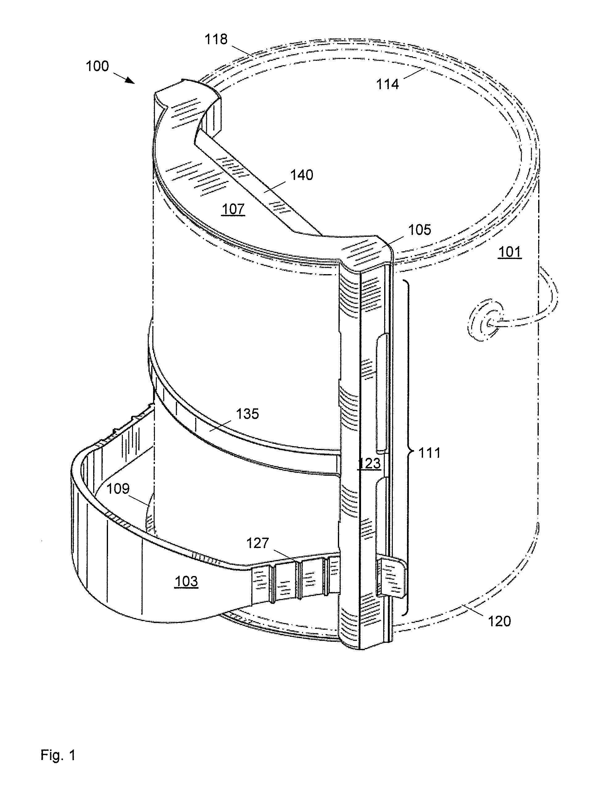
[0092] FIGS. 1 to 9 generally depict non limiting implementations of a paint can holder 100, which attaches to a paint can 101 offering an ergonomic holding alternative to the thin metal wire/handle that typically is found on a paint can In some implementations, paint can 101 can comprise a one-gallon paint can, or a one-pint paint can. However the size of paint can 101 is appreciated not to be limiting and any suitable size of paint can is within the scope of present implementations. Furthermore, paint can holder 100 can also be referred to as a cut can holder as paint cans used for trimming are generally referred to as cut cans.
[0093] Paint can holder 100 generally comprises a strap 103 releasably attachable to paint can 101 such that paint can 101 can be held using strap 103 when paint can holder 100 is attached to paint can 101. In some implementations (not depicted) strap 103 can comprise apparatus for releasably attaching strap 103 to paint can 101, for example engagement portions, hooks or the like that can be attached to the top and bottom of paint can 101. In yet further implementations, strap 103 can comprise apparatus for releasably attaching strap 103 to the sides of paint can 101, for example, additional straps which can be placed under tension around at least a portion of the circumference of a wall of paint can 101. However, the apparatus for releasably attaching strap 103 to paint can 101 is not to be considered particularly limiting and any suitable apparatus for releasably attaching strap 103 to paint can 101 is within the scope of present implementations.
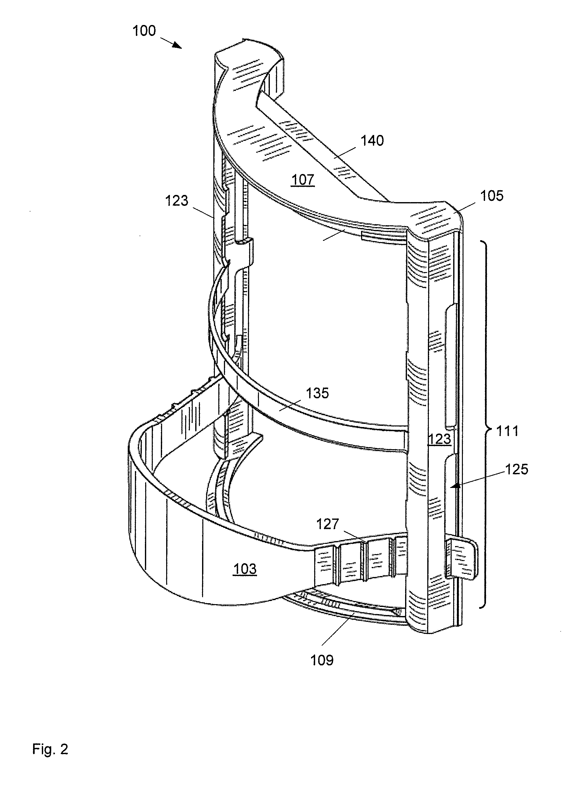
[0094] In some non-limiting implementations, strap 103 is releasably attachable to paint can 101 using a harness 105 attached to strap 103. It is appreciated that strap 103 is adjustable in harness 105, so that strap 103 can be adjusted to a comfortable position for a user, such that a user may insert a hand and/or a portion of an arm (such as a forearm) between paint can 101 and strap 103, as will be described in further detail below. In any event, it is appreciated that in these implementations, paint can holder 100 comprises two pieces: strap 103 and harness 105, strap 103 attached to harness 105. Indeed, it is further appreciated that strap 103 is adjustable in harness 105 and that strap 103 can be detached from harness 105. Further, strap 103 and harness 105 can be manufactured separately from each other.
[0095] It is further appreciated that strap 103 and harness 105 can be manufactured from any suitable material and/or materials, including but not limited to any suitable plastic. Indeed, each of harness 105 and strap 103 can be made from any respective suitable material, such as any respective suitable plastic. Strap 103 can be made from a different or similar material as harness 105. In particular non-limiting implementations, strap 103 can be made from santoprene. It is appreciated that harness 105 is somewhat bendable/flexible to enable harness 105 to be snapped on and off paint can 101, as will be described below. In other words, harness 105 is generally bendable/flexible while generally rigidly holding its shape and is made from any suitable material for enabling such flexibility, and is further of suitable thicknesses and width of the suitable material. Similarly, strap 103 is comprised of a generally bendable/flexible material such that when attached to harness 105, strap 103 can bend (and/or flex) to accommodate an arm of a painter, as will be described below.
[0096] Harness 105 is depicted in detail in FIGS. 11 and 12, according to non-limiting implementations. In these implementations, harness 105 comprises: a top engagement portion 107 for releasably engaging a top of paint can 101. A bottom engagement portion 109 for releasably engaging a bottom of paint can 101 and a connecting portion 111 between top engagement portion 107 and bottom engagement portion 109.
[0097] With reference to FIGS. 1, 2, 3, 8, 11 and 12, top engagement portion 107 is enabled to extend along a portion of a circumference of a top of paint can 101. Similarly, with reference to FIGS. 1, 2, 3, 9, 11 and 12, bottom engagement portion 109 is enabled to extend along a portion of circumference of a bottom of paint can 101. Further, it is appreciated that in depicted non-limiting implementations, top engagement portion 107 and bottom engagement portion 109 are semi-circular in order to extend partially along the circular top and bottom of paint can 101.
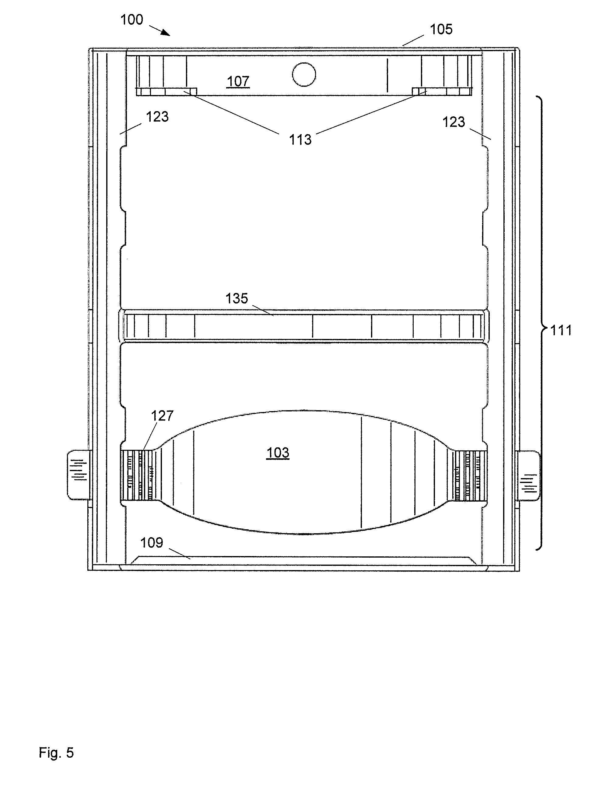
[0098] Attention is now directed to FIGS. 1, 5, 10 and 11. It is appreciated that top engagement portion 107 comprises at least one engagement apparatus 113 that engages an inner ridge 114 of an opening of paint can 101. Further, it is appreciated that in depicted non-limiting implementations engagement apparatus 113 comprises at least one hook that hooks under the inner ridge 114 of an opening of paint can 101, for example two hooks at either end of top engagement portion 107. However, the number of hooks are not to be considered particularly limiting. It is further appreciated that other suitable engagement apparatus are within the scope of present implementations. Furthermore, in depicted implementations, top engagement portion 107 further comprises a ridge 115 that extends from a lip 117 enabled to extend across a top rim 118 of paint can 101 and further extend over the opening of paint can 101. Ridge 115 is enabled to extend into the opening of paint can 101 and along inner edge 114 of the opening and is hence of a complimentary shape. Furthermore, ridge 115 is enabled to extend into the opening a distance that enables engagement apparatus 113 to engage inner ridge 114 of the opening of paint can 101 such that top rim 118 of paint can 101 and inner ridge 114 of the opening of paint can 101 are engaged between lip 117 and engagement apparatus 113, respectively. In other words top rim 118 of paint can 101 and the underside of the opening of paint can 101 engagingly fit between lip 117 and engagement apparatus 113. Hence, harness 105 attaches to top rim 118 paint can 101 using engagement apparatus (e.g. the two hooks), in top engagement portion 107, that grasp inner ridge 114 of the opening of paint can 101.
[0099] In some implementations ridge 115 can extend approximately 0.3 to approximately 0.8 inches from lip 117, though the distance that ridge 115 extends from lip 117 is generally dependent on the size of paint can 101, and the width of engagement apparatus 113. For example for one-gallon size paint cans, ridge 115 can extend 0.615 inches from lip 117. for pint size paint cans, ridge 117 can be shorter, and for other size paint cans (for example metric sizes), ridge 115 can be smaller or larger. It is nonetheless appreciated that the distance that ridge 115 extends from lip 117 is generally non-limiting. In non-limiting implementations, engagement apparatus 113 (e.g. the hooks) can range from approximately 0.08 to approximately 0.2 inches. In particular non-limiting implementations, engagement apparatus 113 can be approximately 0.108 inches wide and approximately 0.1 inches in depth, though these values are generally understood to be non-limiting.
[0100] With reference to FIGS. 1, 10, 11 and 12, bottom engagement portion 109 is generally enabled to engage a bottom ridge 120 of paint can 101. For example, in depicted implementations, bottom engagement portion 109 comprises at least one complimentary ridge 119 for engaging bottom ridge 120 of paint can 101. It is appreciated that bottom ridge 120 generally extends around the circumference of the bottom of paint can 101, and that at least one complimentary ridge 119 engage a portion of bottom ridge 119. It is further appreciated that in depicted implementations, bottom engagement portion 109 comprises a single complimentary ridge 119 that extends along a substantial portion of bottom engagement 109. however in other implementations, bottom engagement portion 109 can comprise any suitable number of complimentary ridges and/or any suitable number of suitable engagement apparatus for engaging the bottom of paint can 101. Complimentary ridge 119 can generally be in a range of 0.08 to 0.2 inches in height, and can depend on the depth of ridge 120 of paint can 101. In particular non-limiting implementations, complimentary ridge 119 can be approximately 0.125 inches in depth, can range from 0.03125 inches to 1.0 inches in depth, though these values are understood to be generally non-limiting.
[0101] Hence, in non-limiting implementations, bottom engagement portion 109 can comprise a semicircular piece that engages bottom ridge 120 found on the bottom of one gallon paint cans, for example via complimentary ridge 119 that extends from bottom engagement portion 109. However, any suitable means of engaging bottom of paint can 101 are within the scope of present implementations and complimentary ridge 119 is not to be considered particularly limiting. Furthermore, bottom engagement portion 109 is connected to vertical arms 123 that further connect to top engagement portion 107 as described hereafter.
[0102] With reference to FIGS. 1-7 and 10-12, it is appreciated that in depicted implementations, connecting portion 111 comprises at least one arm 123 extending a given distance between top engagement 107 portion and bottom engagement portion 109 thereby enabling paint can 101 to snugly fit there between. For example, the given distance can comprise a longitudinal length of paint can 101, and hence the given distance can depend on the longitudinal length of paint can 101. For example a height of a one-gallon paint can is approximately 7.5 inches and hence the given distance at least one arm 123 can be approximately 7.95 inches such that a one gallon paint can fit between top engagement portion 107 and bottom engagement portion 109, though given distance is generally understood to be non-limiting. For smaller paint cans, such as a 1 pint paint can, which is approximately 3.94 inches in height, at least one arm 123 can be approximately 4.2 inches so that the one pint paint can fit between top engagement portion 107 and bottom engagement portion 109. However, at least one arm 123 can be any suitable length for a respective paint can range from approximately 1.9 inches to approximately 10.1 inches. It is further appreciated that in depicted non-limiting implementations, connecting portion 111 comprises two arms 123, extending between top engagement portion 107 and bottom engagement portion 109, each of arms 123 extending between opposite ends of each of top engagement portion 107 and bottom engagement portion 109.
[0103] Hence arms 123 extend between top engagement portion 107 and bottom engagement portion 109 along the longitudinal axis of paint can 101 and can, in some implementations, be in contact with the wall of paint can 101 when harness 105 is attached thereto.
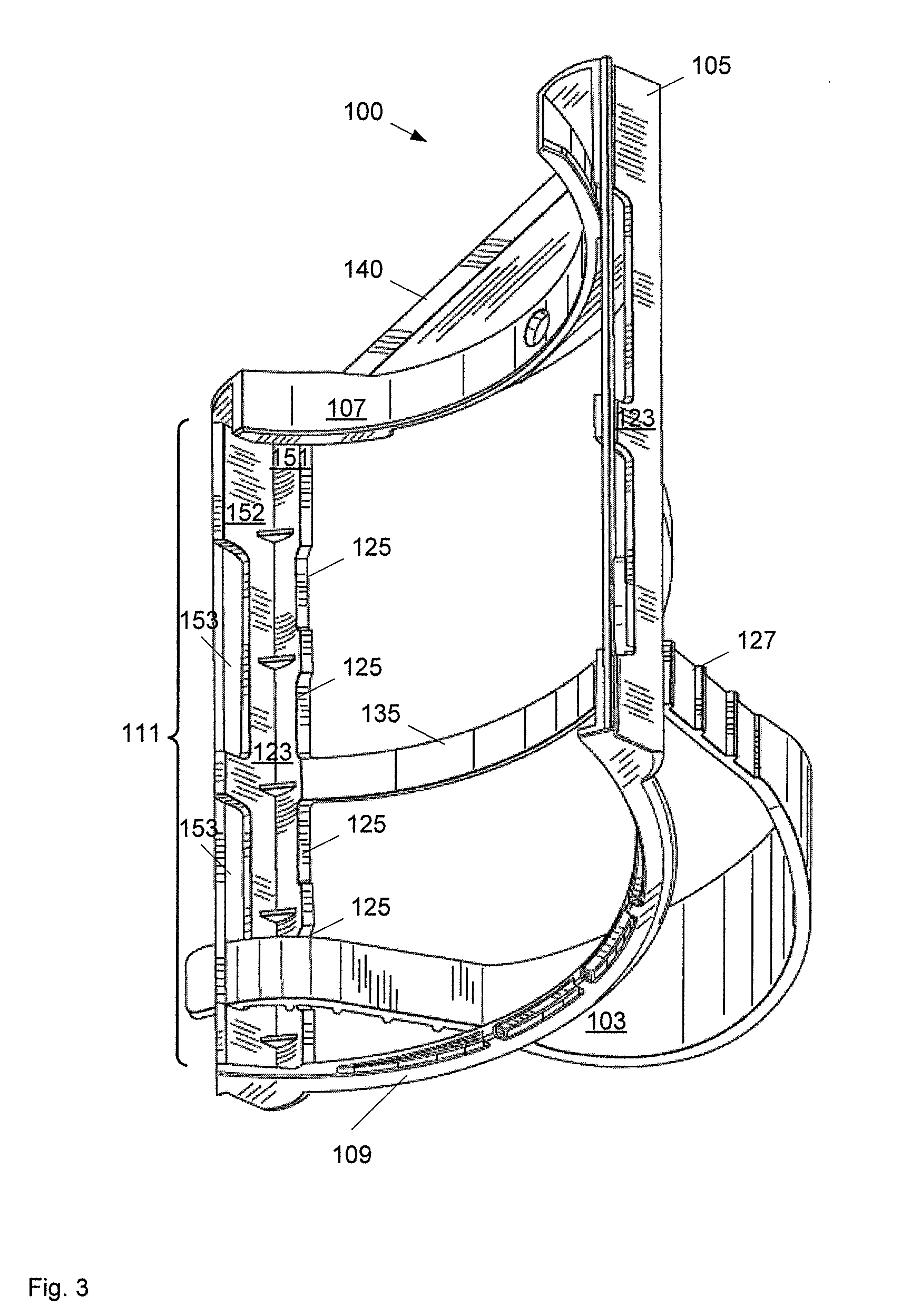
[0104] With reference to FIGS. 3, 5, 7, and 16, in depicted non-limiting implementations, each arm 123 comprises at least one attachment point 125 for attaching strap 103 between arms 123. In depicted implementations, arms 123 each comprise four attachment points 125 and strap 103 can connect to any one of them, one on each side. As depicted, it is appreciated that at least one attachment point 125 comprises a cut out of each arm 123, such that each attachment point 125 defines an opening between a respective arm 123 and paint can 101 when harness 105 is attached to paint can 101, each opening defined by a respective attachment point 125 at least wide enough for receiving strap 103 there through. For example, with reference to FIGS. 1-6, 8-10, 13 and 16, strap 103 generally comprises at least one ridge 127, and wherein at least one ridge 127 engages an attachment point 125 holding strap 103 there in. In specific non-limiting exemplary implementations, strap 103 comprises a plurality of ridges 127 (though only one exemplary ridge 127 is indicated in FIGS. 1-4, 6 and 12), such that strap 103 is adjustable in each attachment point 125 by selecting a given ridge 127 at each end 130 of strap 103 for engaging a respective attachment point 125. Hence, each end 130 acts as a male end, while each opening defined by each attachment point 125 acts as a female end. While in depicted implementations strap 103 comprises five ridges 127 at each end 130 of strap 103 (wherein each end 130 comprises a tongue insertable into an opening defined by an attachment point 125), each ridge spaced approximately 0.5 inches apart, the number of ridges 127 and spacing there between is generally non-limiting and any suitable number of ridges 127 and any suitable spacing there between is within the scope of present implementations. Spacing between ridges 127 can range from approximately 0.125 inches to approximately 2 inches. In specific non-limiting implementations, spacing between ridges 127 can be approximately 0.48 inches.
[0105] As depicted in FIG. 3, which indicates four attachments points 125 on one arm 123, the attachments points on the other arm 123 not being visible, in some implementations, each arm 123 can comprise an inner wall 151 and an outer wall 152 connected at an angle that enables a paint can facing edge of each wall 151, 152 to rest against paint can 101 when paint can holder 100 is attached thereto. In these implementations, attachments points 125 are spaced along inner wall 151 such that strap 103 is received into openings defined by the cut-outs (i.e. attachment points 125) on the inner wall 151. Furthermore, outer wall 152 comprises at least one groove 153 for receiving ends 130 of strap 103 after they are received at attachment points 125. In depicted implementations, each outer wall 152 comprises two grooves 153, an upper groove 153 substantially parallel to and aligned with the two upper attachment points 125 on arm 123 such that the upper groove 153 can receive an end 130 of strap 103 after it passes through either of the upper attachments points 125. Similarly, each outer wall 152 comprises a second lower groove 153 substantially parallel to and aligned with the two lower attachment points 125 on arm 123 such that the lower groove 153 can receive an end 130 of strap 103 after it passes through either of the lower attachments points 125. Grooves 153 provide additional stability for strap 103 and further secure ends 130 as another ridge 127 of strap 103 can engage groove 153. Spacing between ridges 127 can be similar to spacing between an attachment point 125 and an associated grove 153.
[0106] Furthermore, it is appreciated that, any suitable method of attaching strap 103 to arms 123 or the like are within the scope of present implementations. In addition, in some implementations, strap 103 can be attached to at least one of top engagement portion 107 and bottom engagement portion 109 using any suitable method and/or apparatus.
[0107] Hence, it is appreciated that strap 103 is adjustable in harness 105 by adjusting ends 130 of strap 103 into and out of the openings defined by attachment points 125 on each arm 123 to create, for example, a large or smaller space between strap 103 and paint can 101. It is further appreciated that ends 130 of strap 103 can be adjusted up and down in each openings defined by a respective attachment point 125, and that opposite ends 130 of strap 103 can be inserted into an upper opening defined by a respective attachment point 125 on one arm 123 and a lower opening defined by a respective attachment point 125 on the opposite arm 123 so that strap 103 extends diagonally between arms 123, at any suitable angle. As depicted in FIGS. 13 and 18, strap 103 further comprises an arm engagement portion 129 for engaging a portion of an arm of a painter when extended between strap 103 and paint can 101, the arm of the painter including but not limited to fingers, a hand, a forearm or the like. Hence, as strap 103 is adjustable between arms 123 to create more or less space 150 between strap 103 and paint can 101, and as strap 103 is adjustable in opening defined by respective attachment points 125 s and between upper and lower openings defined by respective attachment points 125, strap 103 can be adjusted for the comfort of a given painter.
[0108] It is appreciated from at least FIG. 1, that strap 103 extends along a circumference of paint can 101, when paint can holder 100 is attached to paint can 101, such that a user (such as a painter) can insert an arm, including a hand, along a longitudinal axis of paint can 101 and support paint can 101 by the bottom of paint can 101. In other words, in use, a painter attaches paint can holder 100 to paint can 101, extends his arm through down strap 103 and can support paint can 101 by cupping the bottom with his hand, arm engagement portion 129 keeping paint can 101 leveraged against his arm. Alternatively, user painter can extend his arm down through strap 103 and leverage paint can 101 against his arm using arm engagement portion 129 without having to cup the bottom of paint can 101.
[0109] Hence, it is appreciated that strap 103 can be of a length suitable for ends 130 of strap 103 to fit through engagement points 125 while still leaving enough length for strap 103 to loop out from harness 105 to create space for inserting an arm there through, including but not limited to a hand, forearm or the like. In non-limiting implementations, a length of strap 103 can range from approximately 8 inches to approximately 20 inches with arm engagement portion 129 taking up approximately 30% to approximately 60% of the length. In particular non-limiting implementations, strap 103 is approximately 11.5 inches with arm engagement portion 129 being approximately 5.5 inches, centred in strap 103, with the ends of strap 103 (i.e. tongues) being approximately 3 inches long for insertion into the openings defined by attachment points 125. It is further appreciated that strap 103 can be of any suitable width and any suitable thickness, though arm engagement portion 129 can be wider than ends 130 of strap 103 to provide better leverage and comfort against an arm of a painter, including but not limited to a hand, forearm or the like. In particular non-limiting implementations, ends 130 of strap 103 are approximately 0.75 inches wide and are not wider than opening defined by attachment points 125. Furthermore, arm engagement portion 129 can be any suitable shape for providing comfort and leverage when paint can holder 100 is in use. As depicted arm engagement portion 129 is oval shaped, though any suitable shape is within the scope of present implementations.
[0110] Hence, it is appreciated that strap 103 comprises any suitable number of attachment apparatus at each end 130 which can be attached to arms 123 on a respective side, via the respective attachment point 125, to secure strap 103 to harness 105 at a specific point or various points to accommodate different adjustability and multiple positions. Strap 103 then secures a hand, wrist, forearm or other part of the arm of a painter to paint can 101 making paint can 101 a virtual extension of the arm or body of a painter. Strap 103 can also act as a hook to attach paint can 101 to a ladder, a hook or the like.
[0111] While in depicted implementations, the strap attaches horizontally to the body, in other implementations, the strap can attach vertically to the body, for example extending between top engagement portion 107 and bottom engagement portion 109 using any suitable method and/or attachment apparatus. Hence, in these implementations (not depicted) strap 103 extends along a longitudinal axis of paint can 101, when paint can holder 100 is attached thereto, such that a user can insert a hand between strap 103 and paint can 101 radially to cup a wall of paint can 101.
[0112] Returning to FIG. 1, it is generally appreciated that connecting portion 111 provides structural support for harness 105 and paint can holder 100 and is generally appreciated to be substantially rigid, though flexible enough to enabled paint can holder 100 to be attached to paint can 101 by first slipping top engagement portion 107 over top rim 118 and inner ridge 114, and then snapping bottom engagement portion 109 over bottom ridge 120. To remove paint can holder from paint can 101, harness 105, including connecting portion 111, is flexed so that bottom engagement portion 109 disengages bottom ridge 120, and the paint can holder 100 is rotated slightly using top engagement portion 107 as a pivot to disengage top engagement portion 107 from inner ridge 114.
[0113] To provide further strength to paint can holder 100, in some non-limiting implementations as depicted, connecting portion 111 comprises at least one strengthening arm 135 that extends between arms 123, and is enabled to follow a contour of paint can 101, such that when paint can 101 is engaged by harness 105, strengthening arm 135 is in contact with the wall of paint can 101. The at least one strengthening arm 135 can also provide stability to paint can holder 100 when engaging paint can 101, distributing tension between arms 123 and preventing arms 123 from spreading apart and/or bending due to tension. As such, at least one strengthening arm 135 can be of any suitable width and/or thickness. In non-limiting exemplary implementations strengthening arm 135 can be approximately 0.5 inches wide and approximately 0.125 inches thick. In some implementations, strengthening arm 135 can comprise a width in the range of approximately 0.125 to approximately 2 inches. However, it is appreciated that the width and thickness of strengthening arm 135 can be dependent on a material from which strengthening arm 135 and/or harness 105 is manufactured. Furthermore, it is appreciated that in depicted non-limiting implementations, strengthening arm 135 is located between attachment points 125.
[0114] It is further appreciated that harness 105 can be one integral piece, with top engagement portion 107, bottom engagement portion 109 and connecting portion 111 all integrally connected. In implementations that include strengthening arm 135, strengthening arm 135 can be integrally connected to arms 123. Hence harness 105 can be manufactured as a single piece using any suitable method, such as plastic injection molding. In yet further implementations, strap 103 can be integrated with harness 105 and paint can holder 100 manufactured as single unit.
[0115] In some optional non-limiting implementations, as depicted in FIGS. 1, 2, 3, 8, 9, 11 and 12, top engagement portion 107 can comprise an optional brush scraper that resides over the opening of paint can 101. Hence, optional brush scraper 140 can be integrated into top engagement portion 107 to offer a scraping device to a painter, brush scraper 140 residing over the opening of paint can 101 when paint can holder 100 is attached to paint can 101. For example, when a paint brush is dipped into paint in paint can 101 there is typically too much paint on the brush for application to a surface. A painter would otherwise use the edge of paint can 101 to remove excess paint off the brush prior to application. Hence, in these non-limiting implementations, brush scraper 140 on paint can holder 100 can be used to remove excess paint.
[0116] Further implementations of a paint can holder 100 can include just a strap on its own, without any vertical arms, attached to a paint can using any suitable method. For example, included within the scope of present implementations is any suitable harness that attaches to a paint can that makes it more comfortable to the painter. Further included within the scope of present implementations are hooks and/or snaps at the end of a strap, similar to strap 103, which hook onto the lip of the opening of paint can 101 and bottom ridge 120, thereby attaching the strap thereto, the strap extending along a longitudinal axis of paint can 101. For example an exemplary paint can holder 1900 is depicted in FIG. 19 attached to a paint can 1901, paint can holder 1900 comprising a strap 1907 extending from a top of paint can 1901 to a bottom of paint can 1901 and further comprising a top engagement portion 1903 and a bottom engagement portion 1905. As further depicted in schematic cross section in FIG. 20A, top engagement portion 1903 can be similar to top engagement portion 107 and bottom engagement portion 1905 can be similar to bottom engagement portion 109. An alternative paint can holder 1900A is depicted in FIG. 20B, which is similar to paint can holder 1900 with like elements having like numbers with an "A" appended thereto. However paint can holder 1900A further comprises a stabilizing arm 2000 extending between top engagement portion 1903A and bottom engagement portion 1905A. In any event paint can holder 1900 and 1900A illustrate that variations on paint can holder 100 are within the scope of present implementations.
[0117] In use, for particular non-limiting implementations, harness 105 is attached to paint can 101 by first removing the lid of paint can 101, engaging the lip of the opening of paint can 101 using engagement apparatus 113 (e.g. the two hooks) in the top engagement portion 107 and then snapping the complimentary ridge 119 of bottom engagement portion 109 under ridge 120 at the bottom of paint can 101. An arm of a painter, including at least the hand of a painter, as well and possibly the wrist and/or forearm (depending on the position of strap 103) is then extended through strap 103 along the longitudinal axis of paint can 101 so paint can 101 can be leveraged against the arm of the painter and/or the bottom of paint can 101 be held using the painter's fingers and/or hand. Such a position provides comfort and is generally ergonomic as paint can 101 is being supported by the arm as it hangs, rather than when strap 103 is vertical and paint can 101 is supported by the arm bent perpendicularly from the painter's body. For example, a painter can use the strap to leverage paint can 101 without having to use their fingers or hand to support the bottom of paint can 101. Rather, paint can 101 is leveraged using friction of paint can holder 100 against the painters arm including their hand and/or forearm. For example, the weight of paint can 101 and strap 103 on the back of the arm of the painter can hold paint can 101 in place. Such leverage provides a comfortable means of holding paint can 101.
[0118] When the painter is done, paint can holder 100 can be removed by slightly bending paint can holder 100 holder to disengage complimentary ridge 119 of bottom engagement portion 109 from bottom ridge 120 of paint can 101, and then unhooking top engagement portion 107 from the opening of paint can 101.
[0119] FIGS. 14-17 depict paint can holder 100 attached to paint can 101 and demonstrates paint can holder 100 in use. For example, FIG. 14 depicts a right side view of paint can holder 100 attached to paint can 101, while FIG. 15 depicts a left side view of paint can holder 100 attached to paint can 101, and FIG. 16 depicts a front side view of paint can holder 100 attached to paint can 101. It is appreciated at least from FIG. 16 that logos, artwork and the like can be included on strap 103 and/or harness 105. In particular, artwork on strap 103 can be punched out and/or cut there through, for example on arm engagement portion 129, to provide a convenient method of marking paint can holder 100 or the like.
[0120] FIG. 17 depicts a top view of paint can holder 100 attached to paint can 101, and hence depicts a space 150 between strap 103 and paint can 101 that is created when paint can holder 100 is attached thereto. A painter can then insert an arm into space 150 to leverage paint can holder 100 and paint can 101 against his arm (and optionally support paint can 101 from the bottom).
[0121] Other paint can holders that include a strap releasably attachable to a paint can are within the scope of present implementations. For example, FIG. 21A depicts a paint can holder 2100 that comprises a strap 2101 and hooks 2102 attached to each end of strap 2101 (though only one end of strap 2101 is visible in FIG. 21), hooks 2102 enabled to hook onto at least one of a hole 2110 for a handle of a paint can 2120 and around a protrusion 2125 that encompasses hole 2110, protrusion 2125 as found on 1 gallon paint cans. In FIG. 21A, hooks 2102 hook onto protrusion 2125, and are held in place by the handle of paint can 2120. Alternatively, as depicted in FIG. 21B, which is substantially similar to FIG. 21A, with like elements having like numbers with, however, an "A" appended thereto, the handle of paint can 2120A has been removed, and hooks 2102A comprise an additional piece which is insertable into hole 2110A.
[0122] Similarly, FIG. 22A depicts a paint can holder 2200 that comprises a strap 2201 and hooks 2202 attached to each end of strap 2201, hooks 2202 enabled to hook onto a rim and/or a opening of a paint can 2220. FIG. 22B depicts an alternative implementation, with like elements having like numbers with an "A" appended thereto, however hooks 2202A are connected via a cross piece 2205, which can provide further stability. Cross piece can be integral with hooks 2202A, and/or attached to hooks 2202A in any suitable manner.
[0123] FIG. 23 depicts a paint can holder 2300 comprising a strap 2301 attached to a harness 2302. Harness 2302 comprises an upper portion 2305 enabled to fit in a top ridge of a paint can (not depicted), for example the ridge that the lid of the paint can normally engages. Upper portion 2302 can hence be an annulus enabled to fit in the top ridge of the paint can. Harness 2303 further comprises a bottom portion 2307 which engages the bottom ridge of the paint can (e.g. bottom ridge 120, described above). Bottom portion 2307 is also an annulus enabled to engage the bottom ridge. A first vertical arm 2309 connects top portion 2305 and bottom portion 2307 and is approximately the same height as the paint can to which paint can holder 2300 is to be attached. A second vertical arm 2311 connects top portion 2305 and bottom portion 2307, on a side opposite arm 2309. One of arm 2307 and arm 2309 is hinged one end (e.g. to one of top portion 2305 and bottom portion 2307) and releasably and securely attaches to the other of top portion 2305 and bottom portion 2307. Hence, harness 2302 comprise a frame within which a paint can be inserted when the hinged arm 2307 or 2309 is detached from the corresponding portion 2305 or 2307 and swung outward. Once top portion 2305 is fit in the top ridge on the paint can and bottom portion 2307 engages the bottom ridge on the paint can, the hinged arm 2307 or 2309 can be reattached to the corresponding portion 2305 or 2307 and paint can be supported by strap 2301, for example, by leveraging the paint can against an arm or the like when the arm or the like is inserted between the paint can and strap 2301. It is appreciated that strap 2301 can be attached to harness 2302 using any suitable method and/or apparatus.
[0124] In yet another non-limiting implementation, FIG. 35 depicts a paint can holder 3500 comprising a skeletal frame 3501 which can accept a paint can through a top opening 3503 defined by a top frame 3505 complementary to a bottom and top of a paint can. Frame 3501 further comprises at least two side arms 3507 and a bottom frame 3509, arms 3507 extending from top frame 3501 to bottom frame 3509, the bottom frame 3509 for supporting the paint can held therein. Paint can holder 3500 further comprises a strap 3511 extending from at least one of arms 3507 and/or top frame 3501, strap 3511 extending along a circumference of paint can, when paint can holder 3500 is attached to a paint can. In some implementations, strap 3511 is similar to strap 103, such that a user (such as a painter) can insert an arm, including a hand, along a longitudinal axis of the paint can and support paint can by the bottom of the paint can.
[0125] Hence, present implementations enable a paint can, for example a one-gallon paint can, to be used comfortably as a cut can (i.e as a holder for paint when painting with a brush, for example when trimming). Painters like using one gallon paint cans specifically for how large the opening is and how easy this makes dipping a paint brush. Present implementations further provide an inexpensive and cost effective method for holding a paint can as a painter can recycle the empty paint can after using all of its contents. This further provides an environmentally friendly product that prevents painters from having to use other containers which increases waste.
[0126] Attention is now directed to FIG. 24 which depicts non-limiting implementations of a paint can holder 100a, similar to paint can holder 100, with like elements having like numbers, however with an "a" appended thereto. For example a top engagement portion 107a is similar to top engagement portion 107. However, paint can holder 100a further comprises a paint brush holder 2400 located at an end of top engagement portion 107a, proximal to scraper 140a.
[0127] In general, paint brush holder 2400 comprises a flexible collar 2401 enabled to releasably grip a handle of a paint brush, flexible collar 2401 comprising a gap 2403 for inserting a handle therein, for example as depicted in FIGS. 32A, 32B, 33A, 33B and 33C described below. It is further appreciated that paint brush holder 2400 is positioned on paint can holder 100a such that when flexible collar 2401 is gripping a paint brush handle, the paint brush is suspended at least one of over an opening of paint can and in opening of paint can, for example, see FIGS. 32A and 32B, described below. It is further appreciated that flexible collar 2401 can be enabled to extend approximately radially in towards a centre of an opening of a paint can, however the orientation of the flexible collar 2401 is not to be considered particularly limiting.
[0128] Attention is next directed to FIG. 25 which depicts a top view of paint brush holder 2400 at an end of top engagement portion 107a. From FIG. 25 it is appreciated that in non-limiting implementations, flexible collar 2401 is "C"-shaped. Indeed, in these non-limiting implementations, flexible collar 2401 comprises two flexible arms 2501a, 2501b for gripping a paint brush handle there between, arms 2501a, 2501b attached to a base portion 2503, which is in turn attached to top engagement portion 107a. It is appreciated that respective ends 2505a, 2505b of arms 2501a, 2501b form gap 2403. Hereafter, arms 2501a, 2501b can be referred collectively as arms 2501 and generically as an arm 2501. Similarly, respective ends 2505a, 2505b can be referred collectively as ends 2505 and generically as an end 2505.
[0129] It is further appreciated that each end 2505 is rounded to reduce friction when accepting a paint brush handle there between, via gap 2403. In depicted non-limiting implementations, each end is circular and bulges out from each respective arm 2501.
[0130] It is further appreciated that the flexibility of flexible collar 2401, which is also referred to hereafter as collar 2401, can depend on various factors, including but not limited to, the material of collar 2401, the width, thickness, the radius of curvature of arms 2501 and a spacing S between arms 2501. In general it is appreciated that the width, thickness, the radius of curvature of arms 2501, and spacing S between arms 2501 is such that a handle of a paint brush can be inserted through gap 2403 and gripped by arms 2501 without the paint brush sliding down towards the paint (e.g. deeper into a paint can).
[0131] For example, attention is directed to FIGS. 32A, 32B. FIG. 32B depicts paint can holder 100a releasably attached to a paint can 101a, and a handle 3260 of a paint brush 3250 releasably gripped by paint brush holder 2400 at a point close to a brush portion 3270 (depicted in FIG. 32B). FIG. 32B is similar to FIG. 32A, however FIG. 32B depicts a partial cutaway view of paint can 101a showing brush portion 3270 in paint can 101a, with paint can holder 101a removed for clarity. Further, FIG. 32B depicts paint brush holder 2400 connected to a gasket portion 2800 in an integrated piece 2900, both of which are described below with reference to FIG. 28 and FIG. 29. Comparing FIG. 32A and FIG. 32B, however, it is appreciated that the position of paint brush 3250 is lower in FIG. 32B than in FIG. 32A. This can occur either by initially placing handle 3260 of paint brush 3250 into paint brush holder 2400 at a given height, each of FIGS. 32A, 32B showing different initial placements of brush 3250, or by sliding brush handle 3260 up or down in paint brush holder 2400 after an initial placement. Hence, in FIG. 32A paint brush holder 2400 is holding paint brush 3250 in a first position and in FIG. 32B paint brush holder 2400 is holding paint brush 3250 in a second position, lower than the first position.
[0132] As a further example, attention is directed to FIGS. 33A, 33B and 33C which each depict paint can holder 100a with paint brush holder 2400 holding paint brush 3250 in different respective positions. Arrows 3300a, 3300b, 3300c in each of FIGS. 33A, 33B and 33C, respectively, represent a direction of movement in of paint brush 3250 as a user changes the position of paint brush 3250 in paint brush holder 2400. At each position, paint brush holder 2400 grips paint brush 3250 such that the position does not change until a user again moves paint brush 3250 up or down in paint brush holder 2400. While arrows 3300a, 3300b, 3300c show paint brush 3250 being moved down, in other instances, paint brush 3250 can be moved up in paint brush holder 2400.
[0133] Hence, the position of a paint brush, in a paint can, can be set by moving the handle of the paint brush up and down in paint brush holder 2400, and specifically in collar 2401. Thus, a paint brush can be stored in a given position in collar 2401 either allowing excess paint to drip from the brush into the paint can and/or leaving bristles of a wet brush resting in paint in a paint can to prevent the brush from drying out. In other words, when flexible collar 2401 is gripping a handle of paint brush, a vertical position of the paint brush with respect to an opening of a paint can is changeable by moving handle up or down in flexible collar 2401. Furthermore, as various levels of paint can be left in a paint can, a paint brush can be moved up or down in flexible collar 2401 to adjust for the level of paint: in other words, as the level of paint changes in a paint can, a paint brush can be repositioned in flexible collar 2401 to rest the bristles in the paint at a given level.
[0134] In general, collar 2401 can be made from any suitable plastic, including but not limited to a plastic similar to the other elements of paint can holder 100a, and/or santoprene. However any suitable material is within the scope of present implementations, including but not limited to plastic, rubber, TPU (Thermal Polyurethane), polyurethane, Sarlink, elastomer, polypropylene, polyethylene, ABS (acrylonitrile-butadiene-styrene) PC (polycarnonate), PBT (polybutylene terephthalate), silicone, an injection molded material, and a material cast from a metal die.
[0135] In particular non-limiting implementations arms 2501 can each be approximately 0.25 inches thick and approximately 0.2 inches wide, with a radius of curvature of approximately 0.261 inches. However it is appreciated that arms 2501 can form an oval shape and hence the radius of curvature can change over the length of each arm 2501. For example, proximal to base 2503, each arm 2501 can be curved with a radius curvature of approximately 0.45 inches, narrow to a radius of curvature of approximately 0.261 inches and the straighten out away from base 2503, to then curve around at ends 2505 with a radius of curvature of approximately 0.261 inches. However, the oval shape can have any suitable radius of curvature and/or plurality of radiuses of curvature, and the depicted implementations are not to be considered limiting. Further, it is appreciated that while in depicted implementations, arms 2501 form an oval shape, in other implementations, arms 2501 can form any suitable shape, including but limited to a circular shape, a square shape, a rectangular shape, or any other suitable shape for gripping a handle of a paint brush. In addition, in some implementations, arms 2501, and optionally base 2503 can be shaped to form a logo, for example in the shape of a drop, see FIGS. 36A, 36B, 36C, 37A and 37B described below.
[0136] Further, each of the thickness and width of arms 2501 can be within any suitable range of thicknesses. For example, the thickness and/or width of each arm 2501 can each range from approximately one eighth of an inch to approximately 1 inch, depending on the desired flexibility and the material from which flexible collar 2401 is manufactured. Further the width and/or thickness and/or radius of curvature of an arm 2501 can be the same and/or different from the width and/or thickness and/or radius of curvature of the other arm 2501.
[0137] In some implementations, spacing S between arms 2501 can be approximately 0.38 inches. However, in other implementations, spacing S can range from approximately a sixteenth of an inch to approximately 5 inches. It is appreciated that in the 5 inch range, flexible collar 2401 can be enabled to grip a paint roller However, it is further appreciated that spacing S can be adapted for any given range of brush handles, such that arms 2501 grip a brush handle therein.
[0138] It is hence appreciated that collar 2401 can be adapted for any size of paint brush handle and that a range of sizes of brush handles can fit into a given collar 2401. For example, a collar 2401 with the dimensions described above can accept paint brush handles ranging from approximately 0.25 inches to approximately 3 inches. But is further understood that these dimensions can be changed to suit any other given suitable range of paint brush handles
[0139] Attention is directed to FIG. 26, which depicts a non-limiting top view of alternative implementations of a flexible collar 2401' similar to collar 2401, with like elements having like numbers, however with a prime ' appended thereto. For example, base 2503' is similar to base 2503. However, in these implementations, collar 2401' comprises one arm 2501' that curves back around towards base 2503', and gap 2403' is formed by end 2505' of arm 2503' and base 2503'. Hence, when a paint brush handle is inserted through gap 2403', arm 2501' extends around the paint brush handle to grip the paint brush handle, similar to arms 2501. The dimensions and material of collar 2401' can be of any suitable dimensions and material respectively, and similar to or different from collar 2401 described above.
[0140] Attention is next directed to FIG. 27 which depicts paint can holder 100a releasably attached to a paint can 101a via harness 105a. FIG. 27 is similar to FIG. 1, with like elements having like number, however with an "a" appended thereto. For example paint can 101a is similar to paint can 101. In any event, from FIG. 27 it is appreciated that collar 2401 extends approximately radially towards a centre of an opening of paint can 101a such that a paint brush gripped by collar 2401 is suspended over and/or in the opening of paint can 101a. It is further appreciated that optional non-limiting implementations a top of flexible collar 2401 can be flush with a top of top engagement portion 107a, however whether flexible collar 2401 is flush, or not, with top engagement portion 107a is not to be considered particularly limiting. Further flexible collar 2401 can be adjacent scraper 140a.
[0141] Attention is next directed to FIG. 28 which depicts a bottom perspective view of paint can holder 100a such that a gasket portion 2800 attached to collar 2401 is visible, gasket portion also referred to hereafter as gasket 2800. It is appreciated that gasket portion 2800 extends from flexible collar 2401 along top engagement portion 107a, gasket portion 2800 enabled to fit between top engagement portion 107a and a top rim of a paint can, such as top rim 118a of paint can 101a. Hence, gasket portion 2800 can deform to provide a better grip between paint can holder 100a and paint can 101a. With reference to FIGS. 29A, 29B and 29C gasket portion 2800 and paint brush holder 2400/flexible collar 2401 can form an integral piece 2900. FIG. 29A depicts a bottom view of piece 2900, similar to FIG. 28. FIG. 29B depicts a top view of piece 2900. FIG. 29C depicts a side view of piece 2900. In non-limiting implementations, gasket 2900 is approximately 0.05 inches thick but can range from approximately 0.01 inches to approximately 2 inches. While this thickness and range can be for a gasket made from santoprene, the thickness and range of gasket 2800 can be dependent on the material from which gasket 2800 is manufactured, including but not limited to any suitable plastic, rubber, TPU (Thermal Polyurethane), polyurethane, Sarlink, elastomer, polypropylene, polyethylene, ABS (acrylonitrile-butadiene-styrene) PC (polycarbonate), PBT (polybutylene terephthalate), silicone, an injection molded material, and a material cast from a metal die. Further, in some implementations gasket 2800 can include structural ribbing, for example laterally across gasket 2800 to improve compression against top rim 118a and/or gripping of top rim 118a by gasket 2800.
[0142] In implementations where gasket 2800 is thick, for example from approximately 0.5 inches to approximately 2 inches, gasket 2800 can further be enabled to for adapting paint can holder 100a to hold paint cans of different sizes. For example, paint can holders 100a, as described above, can be generally of dimensions that enable paint can holder 100a to hold a one gallon paint can. However, paint can holder 100a can be adapted to hold paint cans smaller than a one gallon paint can by inserting, for example, integral piece 2900 with a gasket that is two inches thick, Hence, a paint can that is two inches shorter than a one gallon paint can, can then be held by paint can holder 100a. Indeed, it is appreciated that as integral piece 2900 can be removable from paint can holder 100a, paint can holder 100a can be supplied with a plurality of integral pieces similar to integral piece 2900, with each of the plurality of integral pieces having respective gaskets (similar to gasket 2800) of different thicknesses such that paint can holder 100a can be adapted to hold a variety of paint cans of different sizes.
[0143] It is yet further appreciated that while gasket 2800 has been described as ranging from approximately 0.5 inches to approximately 2 inches for adapting paint can holder 100a to hold paint cans of different sizes, this range is not to be considered particularly limiting and any other suitable thickness of gasket 2800 is within the scope of present implementations. For example, gasket 2800 can be less than 0.5 inches thick and greater than 2 inches thick and still be used to adapt paint can holder 100a to hold paint cans of different sizes. Indeed, it is appreciated that as different sizes of paint cans become available (smaller than paint can 101a) gasket 2800 can be made using a thickness suitable for adapting paint can holder 100a to hold a paint can of a given size.
[0144] It is further appreciated that in some implementations, integral pieces (similar to integral piece 2900) can be provided without paint brush holder 2400 such that paint can holder 100a can be adapted for attachment to different size paint cans without the paint brush holder feature. Further, it is appreciated that integral portions (such as integral portion 2900) with different gasket thicknesses can be provided separate from paint can holder 100a (e.g. sold as an accessory for paint can holder 100a) such that paint can holder 100a can be adapted for attachment to different size paint cans after an initial purchase of paint can holder 100a. For example a single integral portion having a given gasket thickness can be sold, or a kit of integral portions with different size gasket thicknesses can be sold. Further, whether in a kit or individually, such integral portions can be provided with or without paint brush holder 2400.
[0145] Hence, it is appreciated that integral piece 2900 is removably attachable to harness 105a using any suitable mechanism. For example, with reference to FIGS. 28, 29A, and 29B, it is appreciated that integral piece 2900 can be attached to harness 105 via at least one of: at least one hook 2901 at an end of gasket 2800 opposite flexible collar 2401, and at least one snapping mechanism 2903 on gasket 2800 adjacent flexible collar 2401 for snapping gasket into a corresponding mechanism on harness 105a underneath top engagement portion 107a. Furthermore, in some implementations (not depicted) a tongue and groove mechanism can be provided along gasket 2800, with a mating portion provided along a bottom of top engagement portion 107a, such that gasket 2800 can be attached to the bottom of top engagement portion 107a by mating the tongue and groove mechanism with the mating portion on the bottom of top engagement portion 107a. It is further appreciated that any suitable mechanism for attaching and/or securing integral piece 2900 to paint can holder 100a is within the scope of present implementations.
[0146] Further, it is appreciated that in some implementations, integral piece 2900 can be removed from paint can holder 100a and reinserted into paint can holder 100a with paint brush holder 2400 now located on a side opposite the original position of paint brush holder 2400. For example attention is directed to FIGS. 34A, 34B and 34C. FIG. 34A depicts a paint can holder 100b, similar to paint can holder 100a, however with an integral piece 2900a (depicted in FIG. 34B), similar to integral piece 2900. With reference to FIG. 34B, integral piece 2900a comprises a paint brush holder 2400a and attached gasket portion 2800a. In some implementations integral piece 2900a can be symmetric about a longitudinal plane, however such an implementation is not to be considered particularly limiting. In any event, paint brush holder 2400a and gasket portion 2800a are generally respectively similar to paint brush holder 2400 and attached gasket portion 2800. In any event, integral piece 2900a is enabled to be removed from paint can holder 100b and rotated 180.degree. about the longitudinal plane, as represented by arrow 3400, and then reinserted into paint can holder 100b, however with paint brush holder 2400a being on a side of paint can holder 100b opposite an original position of paint brush holder 2400a, as depicted in FIG. 34C. Correspondingly, paint can holder 100b is enabled to receive integral piece 2900a in either position. In implementations where integral piece 2900 is symmetric about a longitudinal plane, paint brush holder 2400a can be of a similar height with respect to top portion 107a in either position, otherwise paint brush holder 2400a can be at different heights with respect to top portion 107a in each position.
[0147] In any event, integral piece 2900a can be positioned in paint can holder 100b in any manner that is convenient for a painter to secure brush 3250 in paint brush holder 2400a. For example, paint can holder 100b can then be conveniently adapted for use with right handed painting or left handed painting: in right handed painting, paint can 101a can be held via paint can holder 100a in a painter's left hand and brush 3250 held in a painter's right hand, while in left handed painting, paint can 101a can be held via paint can holder 100a in a painter's right hand and brush 3250 held in a painter's left hand, with paint brush holder 2400a being positioned on paint can holder 100b in any of the two positions which is most convenient for a given painter to secure brush 3250 in paint brush holder 2400a.
[0148] While in FIGS. 24-29, paint brush holder 2400 has been described with reference to paint can holder 100a, and specifically as an element thereof, any suitable apparatus for releasably attaching flexible collar 2401 to a paint can is within the scope of present implementations.
[0149] For example, attention is directed to FIG. 30, which depicts a paint brush holder 2400b comprising a flexible collar 2401b similar to collar 2401 and an attachment portion 3000 for attaching paint brush holder 2400b to a top rim of paint can 101a. Paint brush holder 2400b is also depicted in a side view in FIG. 31 where it is appreciated that attachment portion 3000 comprises a groove 3001 that fits over top rim 118a, and is curved accordingly, with groove 3001 being of a width complementary to the width of top rim 118a. Further attachment portion 3000 can be any suitable width and depth for providing leverage to prevent paint brush holder 2400b from twisting off of rim 118a when a paint brush is held in flexible collar 2401b. Further attachment portion 3000a and groove 3001 can be flexible such that groove 3001 deforms to grip top rim 118a when attached thereto, providing further frictional support for attachment portion 3000. Further, paint brush holder 2400b can be of any suitable length, for example a length to hold a paint brush proximal a side of paint can 101a.
[0150] It is yet further appreciated that any suitable apparatus can be connected to flexible collar 2401, 2401a, 2401b, for releasably attaching flexible collar 2401, 2401a, 2401b to a paint can such that when flexible collar 2401, 2401a, 2401b is gripping a handle of a paint brush, the paint brush is suspended at least one of over an opening of the paint can and in the opening of the paint can. For example flexible collar 2401, 2401a, 2401b can be attached to a paint can via any of harnesses 105, harness 105a, and paint can holders 1900, 1900A and 3500.
[0151] It is further appreciated that harnesses and strap combinations substantially similar to harness and strap combinations described herein could be provided as a standard feature on paint cans, for example replacing the wire-like handle, and added at the manufacturing stage of paint cans: for example, presently, wire-like handles does not enable paint cans to be held in the manner described herein. In such implementations, harness and strap combinations could be provided substantially integral with paint cans, or as removable piece(s)
[0152] Attention is now directed to FIGS. 36A, 36B and 36C, which are substantially similar to FIGS. 29A, 29B and 29C respectively, with like elements having like numbers, however with a "c" appended thereto. For example, integral piece 2900c is similar to integral piece 2900. However, paint brush holder 2400c is in the shape of a logo, with the arms and base of paint brush holder 2400c forming a drop shape. Hence, from FIGS. 36A, 36B and 36C, it is understood that paint brush holder 2400c can be formed into any suitable shape for releasably gripping a handle of a paint brush, as can a gap for inserting a handle of a paint brush therein.
[0153] Similarly, FIGS. 37A and 37B depict top and bottom view respectively of a paint brush holder 2400d, similar to paint brush holder 2400b, with a base 3700 and arms 3701a, 3701b forming a logo into the shape of a drop, as in paint brush holder 2400c. Hence, from FIGS. 37A, and 37B it is understood that paint brush holder 2400d can be formed into any suitable shape for releasably gripping a handle of a paint brush, as can a gap for inserting a handle of a paint brush therein formed by arms 3701a, 3701b.
[0154] Hence, provided herein are various implementations of a paint brush holder releasably gripping a handle of a paint brush at least one of over an opening of a paint can and in the opening of the paint can. Hence, a painter can conveniently insert the paint brush into the paint brush holder and take a break from painting without having to clean the brush as excess paint drips from the brush into the paint can. Further, as a painter only has two hands, when a painter wants to use his/her painting hand for something other than painting, they can temporarily stow the brush in the paint brush holder. The paint brush holder can further be adapted to suit any suitable size of paint brush including but not limited to paint brushes with bristles and paint rollers
[0155] Furthermore, as the position of the brush in the paint brush holder is adjustable and hence the paint brush handle can be adjusted to any suitable height in the paint brush holder, the painter can conveniently position the paint brush in any suitable height in the paint brush holder such that the bristles of the brush are resting in the paint in the paint can, thereby preventing the bristles from drying out. Furthermore, in specific non-limiting implementations, a paint brush holder attached to a paint can holder can be conveniently placed in at least two positions on the paint brush holder to adapt the paint can holder for left or right handed painting. When a gasket is attached thereto, the gasket can be provided of any suitable thickness for adapting the paint can holder to hold a given size of paint can.
[0156] Attention is now directed to FIGS. 38 and 39 which depict a paint can strap 3800, according to non-limiting implementations. In FIG. 38 paint can strap 3800 is depicted in an assembled perspective view and in FIG. 39, paint can strap 3800 is depicted in an exploded perspective view. Paint can strap 3800 comprises a strap portion 3801 comprising a first end 3803a and a second end 3803b distal first end 3803a. Paint can strap 3800 further comprises a first attachment portion 3805a at first end 3803a. Paint Can strap 3800 further comprises a second attachment portion 3805b at second end 3805b. First end 3803a and second end 3803b will be referred to collectively hereafter as ends 3803 and generically as end 3803. Furthermore this convention will be used throughout the specification. It is generally appreciated that in present implementations, each attachment portion 3805 is removably attachable to a respective end 3803, as in FIG. 38, and that each attachment portion 3805 can be removed from each respective end 3803, as in FIG. 39. However, in other implementations it is appreciated that attachment portions 3805 and strap portion 3801 can be integral.
[0157] As depicted in FIG. 40, where paint can strap 3800 is depicted as attached to a paint can 4001, each attachment portion 3805 is enabled for releasable attachment to a handle 4003 of paint can 4001 such that at least one of a hand and an arm can be inserted between strap portion 3801 and paint can 4001, and along a longitudinal axis of paint can 4001, to leverage paint can 4001, similar to paint can holder 100 described above. Though only attachment portion 3805b is visible in FIG. 40, it is appreciated that attachment portion 3805a is present, though hidden behind paint can 4001.
[0158] As is further appreciated from FIG. 40, when paint can strap 3800 is attached to handle 4003 by attachment portions 3805, strap portion 3801 extends along a circumference of paint can 4001. As is further appreciated from FIGS. 40 and FIG. 41, which depicts paint can strap 3800 attached to handle 4003, without paint can 4001 for clarity, each attachment portion 3805 is attached to handle 4003 on opposite sides of handle 4003, proximal to respective pivots 4007a, 4007b of handle 4003.
[0159] Attention is now directed to FIGS. 42A, 42B, and 42C, which respectively depict a perspective front view, a side view and a perspective rear view of an attachment portion 3805. Each attachment portion 3805 comprises a body portion 4201 and a hook portion 4203. Hook portion 4203 is enabled for releasably hooking strap portion 3801 to handle 4003 (e.g. as in FIGS. 40 and 41). It is furthermore appreciated that hook portion 4203 extends towards strap portion 3801 from a paint can handle attachment end 4207 of attachment portion 3805. From FIG. 42B, it is appreciated that a gap 4209 is formed between hook portion 4203 and body portion 4201, gap 4209 enabled to receive handle 4003. In present implementations, handle 4003 comprises a wire handle, and hook portion 4203 and gap 4209 are enabled to receive a wire handle. Further, in present implementations, gap 4209 can range from approximately 0.05 inches to approximately 0.75 inches.
[0160] However, in other implementations, hook portion 4203 and gap 4209 are enabled to receive any suitable handle of any suitable paint can. For example, while paint cans which are presently on the market are sold with a wire handle with diameters ranging from approximately 0.1 inch (approximately 3 mm) to approximately 0.2 inch (approximately 5 mm), should paint can handles change to other materials, diameters and/or configurations, hook portion 4203 and/or gap 4209 can easily be adapted. For example, portion 4211 (which attaches hook portion 4203 to body portion 4201) can be made longer or shorter during manufacture of attachment portion 3805, thereby respectively increasing and decreasing gap 4209, to accommodate different types of paint can handles. Furthermore, as will be described below, as attachment portion 3805 is releasably attachable to strap portion 3801, different types of attachment portions 3805 can be provided with (or separately from) strap portion 3801 such that strap portion 3801 can be adapted for attachment to different types of paint can handles.
[0161] As can also be seen from FIG. 42B, in present implementations, hook portion 4203 can optionally comprise a protrusion 4213 that protrudes from hook portion 4203 towards body portion 4201. Protrusion 4213 is generally enabled for holding handle 4003 in gap 4209, between hook portion 4203 and body portion 4201. Indeed, it is appreciated that hook portion 4203 can be flexible such that when handle 4003 is inserted into gap 4209, hook portion 4203 flexes away from body portion 4201 as handle 4003 displaces protrusion 4213. Hook portion 4203 then snaps back to a resting position as handle 4003 passes protrusion 4213 and is thereby hooked in gap 4209 by hook portion 4203. For clarity, handle 4003 is depicted in cross-section in FIG. 42B in the hooked position.
[0162] FIG. 42C further illustrates a shape of hook portion 4203 in depicted implementations being generally semi-circular, which can aid in handle 4003 and attachment portion 3805 pivoting relative to one another, as described below with respect to FIGS. 47A and 47B. However, the shape of hook portion 4203 is appreciated to be generally non-limiting.
[0163] It is yet further appreciated that, each attachment portion 3805 comprises respective handle attachment apparatus, such as hook portion 4203, at paint can handle attachment end 4207, each respective handle attachment apparatus for releasably attaching handle 4003 to attachment portion 3805. While present implementations are described with reference to handle attachment apparatus comprising hook portion 4203, in other implementations, handle attachment apparatus can comprise any suitable handle attachment apparatus, including but not limited to a clip, a clasp, a fastener, and any other suitable apparatus for releasably attaching attachment portion 3805 to handle 4003. In some implementations, handle attachment apparatus can be similar to hooks 2102 depicted in FIG. 21, though adapted to be hooked to handle 4003.
[0164] Returning to FIG. 42B, it is appreciated that a distance between portion 4211 and protrusion 4213 can be greater than a diameter of handle 4003 such that attachment portion 3805 can pivot about handle 4003. For example, attention is directed to FIGS. 47A and 47B, which each depict attachment portion 3805 with handle 4003 hooked in hook portion 4203. In FIG. 47A, handle 4003 is in a first position and in FIG. 47B, handle 4003 is in a second position, with at least with one of handle 4003 and attachment portion 3805 having pivoted about one another. Hence, it is appreciated that the dimensions of hook portion 4203 are such to enable handle 4003 and attachment portion 3805 to pivot relative to one another. For example, in depicted implementations, a distance between protrusion 4213 and portion 4211 is approximately 0.25 inches, gap 4209 is approximately 0.06 inches, and protrusion 4213 is approximately 0.25 inches wide (from side to side). However, it is appreciated that any suitable combination of dimensions for enabling handle 4003 and attachment portion 3805 to pivot relative to one another is within the scope of present implementations.
[0165] Furthermore, the shape of hook portion 4203 is generally semi-circular in present implementation (e.g. as depicted in FIGS. 42C and 45) which can assist in handle 4003 and attachment portion 3805 pivoting relative to one another; such a shape ensures that there is clearance for handle 4003 to pivot (e.g. "rock" like a rocking chair) in hook portion 4203, to accommodate different angles.
[0166] To further illustrate the pivot functionality, attention is next directed to FIGS. 43A, 43B, and 43C which each depict a paint can strap 4300, similar to paint can strap 3800, attached to paint can 4001 in three (3) different positions as paint can strap 4300 pivots about handle 4003, as represented by arrows 4310a, 4310b, 4310c, respectively. Paint can strap 4300 comprises a strap portion 4301, similar to strap portion 3801, removably attached to attachment portions 4305, which in turn are removably attached to handle 4003. It is appreciated that only one attachment portion 4305 is visible in FIGS. 43A, 43B and 43C, the other hidden by paint can 4001. Attachment portion 4305 is similar to attachment portion 3805, however attachment portion 4305 comprises an extension for attachment to strap portion 4301, as described in more detail below with respect to FIG. 49.
[0167] In any event, FIG. 43A depicts paint can strap 4300 in a use position, such that strap portion 4301 extends along a circumference of paint can 4001 and fowls a gap 4320 between paint can strap 4300 and paint can 4001 such that at least one of a hand and an arm can be inserted in gap 4320, between strap portion 4301 and paint can 4001, and along a longitudinal axis of paint can 4001, to leverage paint can 4001.
[0168] FIG. 43C depicts paint can strap 4300 in a resting position where an edge of strap portion 4301 rests against a wall of paint can 4001: for example, when the hand or arm is removed from gap 4320, paint can strap 4300 falls to the resting position in FIG. 43A as handle 4003 and attachment portions 4305 pivot relative to one another. FIG. 43B depicts a position intermediate to the use position of FIG. 43A and the resting position of FIG. 43C; it is appreciated that in some implementations, the position of FIG. 43B can comprise an alternative use position as described below, for example when it is desired to use paint can strap 4300 with just a hand inserted in gap 4320, instead of a forearm. It is further appreciated that when a hand or an arm is inserted between paint can strap 4300 and paint can 4001, paint can strap 4300 will naturally pivot, via attachment portions 4305, to accommodate different size arms and/or hands and that other in-use positions, paint can strap 4300 can be off-parallel from a wall of paint can 4001, similar to FIG. 43B.
[0169] Attention is now directed back to FIG. 42A, and specifically to a plurality of openings 4210, each opening 4210 comprising a slot for receiving an end 3803 of strap portion 3801 such that attachment portion 3805 can be releasably attached to strap portion 3801. As will be presently explained, however, it is appreciated that each attachment portion 3805 comprises paint can handle attachment end 4207, and a strap attachment end 4215 distal paint can handle attachment end 4207. Further, strap attachment end 4215 comprises a strap attachment apparatus such as openings 4210, for attaching strap portion 3801 to each attachment portion 3805.
[0170] For example attention is next directed to FIGS. 44, 45 and 46, which respectively front, rear, and side perspective views of attachment portion 3805b attached to end 3803b. It is appreciated from FIGS. 44, 45 and 46 that end 3803b has been woven through adjacent slots/openings 4210, at least one of a plurality of ridges 4427 at strap portion 3801 engaging at least one of slots/openings 4210. It is appreciated that ridges 4427 are similar to ridges 127 described above.
[0171] It is further appreciated that each attachment portion 3805 are releasably attached to a respective end 3803 of strap portion 3801, and that strap portion 3801 is adjustable at each attachment portion 3805. For example, each attachment portion 3805 comprises at least one opening 4210 for receiving a respective end 3803 of strap portion 3801. Further, strap portion 3801 comprises at least one ridge 4427 for engaging at least one of openings 4210, holding strap portion 3801 there in. As strap portion 3801 in present implementations comprises a plurality of ridges 4427, strap portion 3801 is adjustable in openings 4210 by selecting a given ridge 4427 for engaging at least one of openings 4210, for example by weaving end 3803 through adjacent openings 4210, such that at least one of the plurality of ridges 4427 engages at least one of plurality of openings 4210. It is furthermore appreciated that strap portion 3801 is adjustable in attachment portion 3805 by moving strap portion 3801 in and out of openings 4210 such that different ridges 4427 can engage openings 4210.
[0172] For example, attention is directed to FIGS. 48A and 48B, which depict paint can strap 4300 described above, comprising strap portion 4301, similar to strap portion 3801, and attachment portions 4305, similar to attachment portions 3805. FIGS. 48A and 48B are each similar to FIG. 43B. FIG. 48A depicts strap portion 4301 in a first position relative to attachment portions 4305, and FIG. 48B depicts strap portion 4301 in a second position relative to attachment portions 4305. The adjustability of strap portion 4301 relative to attachment portions 4305 is indicated by arrow 4900 of FIG. 48A. In the first position of FIG. 48A, strap portion 4301 is adjusted such that gap 4320 between strap portion 4301 and paint can 4300 is at a maximum: in other words, strap 4301 has been removed as far as possible from attachment portion 4305 while still being attached to attachment portion 4305. In the second position of FIG. 48B, strap portion 4301 is adjusted such that gap 4320 between strap portion 4301 and paint can 4300 is at a minimum: in other words, strap 4301 has been inserted as far as possible into attachment portion 4305. Hence, strap portion 4301 can be adjusted to fit a wide range of hand and arm sizes. For example, strap portion 4301 can be adjusted such that gap 4320 can range from approximately 0.5 inches to approximately 8 inches. However, to accommodate different sizes, a length of strap portion 4301 (or strap portion 3801) can be increased or decreased.
[0173] Indeed, in present implementations, it is appreciated that a distance from distal ends of each attachment portions 4305 (or attachment portions 3805) can range from approximately 10 inches to approximately 20 inches.
[0174] Attention is now directed to FIG. 49 which depicts a front view of attachment portion 4305. Attachment portion 4305 is similar to attachment portion 3805, and includes a hook portion (not visible), similar to hook portion 4203, and a body portion 4901, similar to body portion 3801, however body portion 4901 further comprises a strap attachment portion 4903 extending from body portion 4901 at an end distal a handle attachment end 4907. Strap attachment portion 4903 comprises openings 4910 similar to openings 4210, wherein strap portion 4301 (and/or strap portion 3801) can be removably attached as described above. By including strap attachment portion 4903 extending from body portion 4901, gap 4320 can be given a wider range of adjustability, as the length of strap attachment portion 4903 is added to the length of paint can strap 4300.
[0175] In depicted implementations, attachment portion 4305 comprises a cut-out 4913 proximate a handle attachment end 4907, which enables paint can strap 4300 to be hung from a hook, or the like, to store paint can strap 4300. It is further appreciated that paint can strap 3800 can be hung from a hook, or the like via one of openings 4210, to store paint can strap 3800.
[0176] Strap portions 3801, 4301, and attachment portions 3805, 4305 can be manufactured from any suitable material, including but not limited to at least one of a plastic, santoprene, rubber, TPU (Thermal Polyurethane), polyurethane, Sarlink, elastomer, polypropylene, polyethylene, ABS (acrylonitrile-butadiene-styrene) PC (polycarbonate), PBT (polybutylene terephthalate), silicone, an injection molded material, a material cast from a metal die, and the like, or any other suitable material. In some implementations, attachment portions 3805, 4305 can be manufactured from a harder, less flexible material than strap portions 3801, 4301 to provide more stability for attaching to handle 4300. For example, in specific non-limiting implementations, attachment portions 3805, 4305 can include, but are not limited to glass-filled polypropylene, or any other suitable material.
[0177] Attention is now directed to FIG. 50, which depicts paint can strap 5300 similar to paint can strap 4300, attached to a paint can 5001, similar to paint can 4001. Paint can strap 5300 comprises a strap portion 5301, similar to strap portion 4301, and attachment portions 5305 (only one of which is visible in FIG. 50). However, in these implementations, each attachment portion 5305 comprises a carabineer attached to strap portion 4301 via any suitable attachment apparatus 5335, including but not limited to hooks, straps, integrally moulded apparatuses, or the like. While the position of attachment portions 5305 are appreciated to be adjustable in FIG. 50, in other implementations, the position can be fixed. From FIG. 50 it is appreciated that any suitable apparatus can be used to hook a paint can strap to the handle of a paint can, including but not limited to hooks, straps, carabineers, a combination thereof, or the like.
[0178] Attention is next directed to FIG. 51 which depicts a paint can strap 5500, attached to a handle 5510 of a paint can 5520. In these implementations, however, paint can strap comprises a attachment portion 5530 for strapping paint can strap 5550 to handle 5510, generally midway between attachment points 5540 at paint can 5520. In yet further implementations, paint can strap 5500 can be attached off-centre to position paint can 5520 in front of a user's body when painting. Paint can strap 5500 further comprises a sleeve 5550 through which at least one of a hand and an arm can be inserted between along a longitudinal axis of said paint can, to leverage said paint can; in some implementations, only the four fingers of a user can fit into sleeve 5550, with the user's thumb external to sleeve 5550. In yet further implementations, sleeve 5550 could accommodate an entire hand, wrist or forearm.
[0179] In any event, tension transmitted by a user's hand from sleeve 5550 to handle 5510 provides leverage to support paint can 5520 against the user's arm and/or the user's fingers and/or hand placed under paint can 5530 when the user's hand, forearm, arm etc. is inserted through sleeve 5550. Sleeve 5550 can, in some implementations, comprise a glove to further distribute leverage and/or tension of paint can 5520 on a user's hand; the finger portions of the glove can be open or closed as desired. In any event it is appreciated that at least one of at least a portion of a user's hand (e.g. fingers and/or an entire hand), a wrist and/or forearm can be accommodated by sleeve 5550.
[0180] Sleeve 5550 can be rigid or flexible as desired, and comprise any suitable material, including but not limited to santoprene. However any suitable material is within the scope of present implementations, including but not limited to plastic, rubber, TPU (Thermal Polyurethane), polyurethane, Sarlink, elastomer, polypropylene, polyethylene, ABS (acrylonitrile-butadiene-styrene) PC (polycarnonate), PBT (polybutylene terephthalate), silicone, an injection molded material, and a material cast from a metal die.
[0181] Sleeve 5550 can also be of any suitable dimensions: for example, sleeve 5550 can range from approximately 0.5 inches to 8 inches wide (i.e. a vertical dimension when paint can strap 5500 is strapped to handle 5510), with wider straps providing wider distribution of tension over the hand/forearm/arm of a user. The circumference of sleeve 5550 can range from approximately 6 inches to approximately 15 inches; however it is appreciated that the circumference of sleeve 5550 can be any suitable length that enables a hand and/or a forearm and/or an arm to pass there through.
[0182] It is further more appreciated that attachment portion 5530 can be attached to sleeve 5550 in any suitable manner, including but limited to an integrated structure, a clip, a strap, glued, a combination, and the like. Furthermore, while attachment portion 5530 is appreciate to be depicted as a clip in FIG. 51, in other implementations, attachment portion 5503 can comprise any suitable number of clips, straps, hooks, Velcro.TM. straps, a combination, and the like. Indeed, it is appreciated that attachment portion 5530 is generally non-limiting, as long as attachment portion releasably attaches sleeve 5550 to handle 5530.
[0183] It is further appreciated that sleeve 5550 could be used to lift paint can 5520 via handle 5510 to distribute weight of paint can 5520 on a user's hand, or the like, such that handle 5510 does not cut into the hand (or the like) of the user.
[0184] In any event, present implementations enable a paint can, for example a one-gallon paint can, to be used comfortably as a cut can (i.e as a holder for paint when painting with a brush, for example when trimming). Painters like using one gallon paint cans specifically for how large the opening is and how easy this makes dipping a paint brush. Present implementations further provide an inexpensive and cost effective method of holding a paint can as a painter can recycle the empty paint can after using all of its contents. This further provides an environmentally friendly product that prevents painters from having to use other containers which increases waste.
[0185] Persons skilled in the art will appreciate that there are yet more alternative implementations and modifications possible for implementing the implementations, and that the above implementations and examples are only illustrations of one or more implementations. The scope, therefore, is only to be limited by the claims appended hereto.
* * * * *
D00000
D00001
D00002
D00003
D00004
D00005
D00006
D00007
D00008
D00009
D00010
D00011
D00012
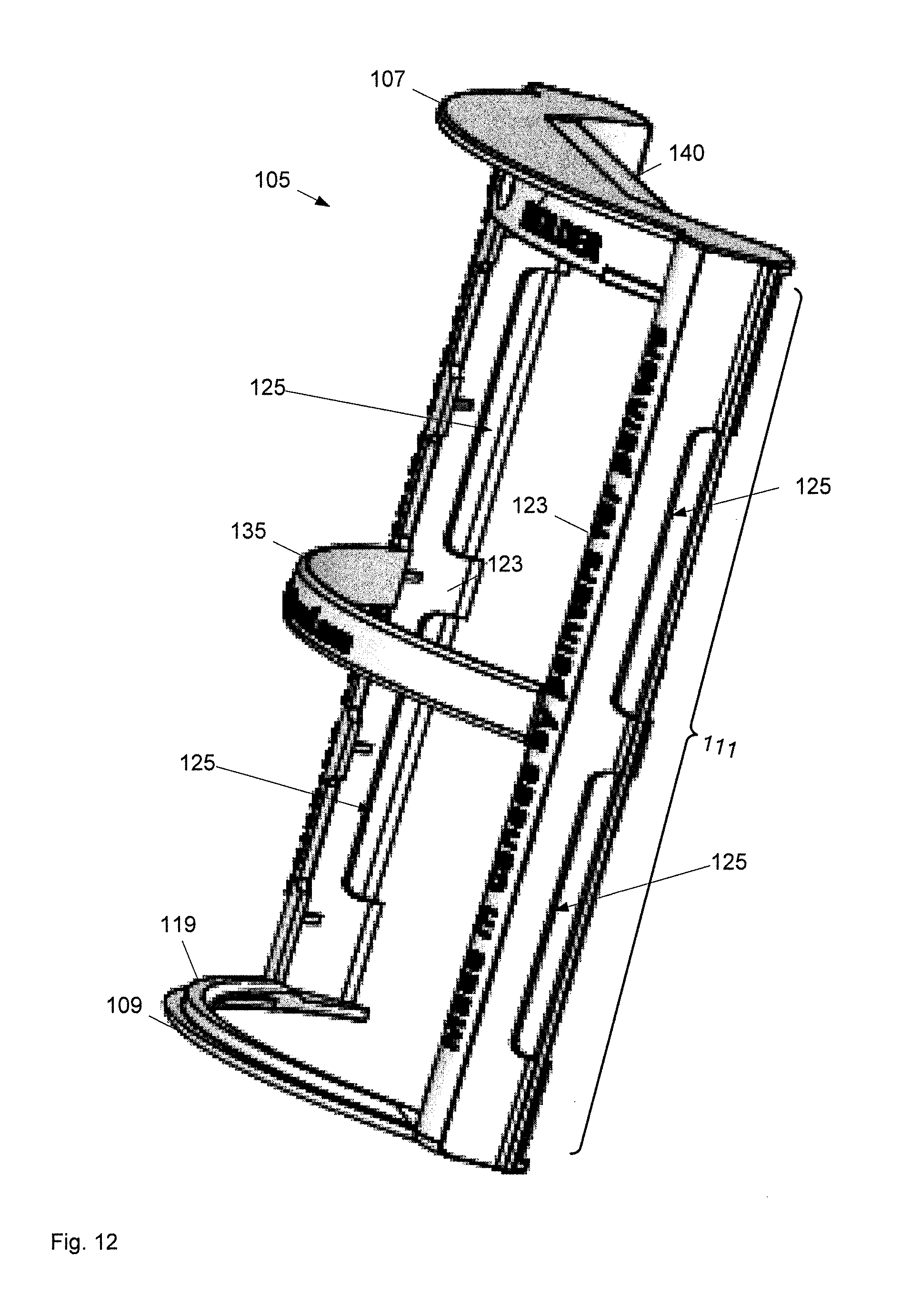
D00013

D00014
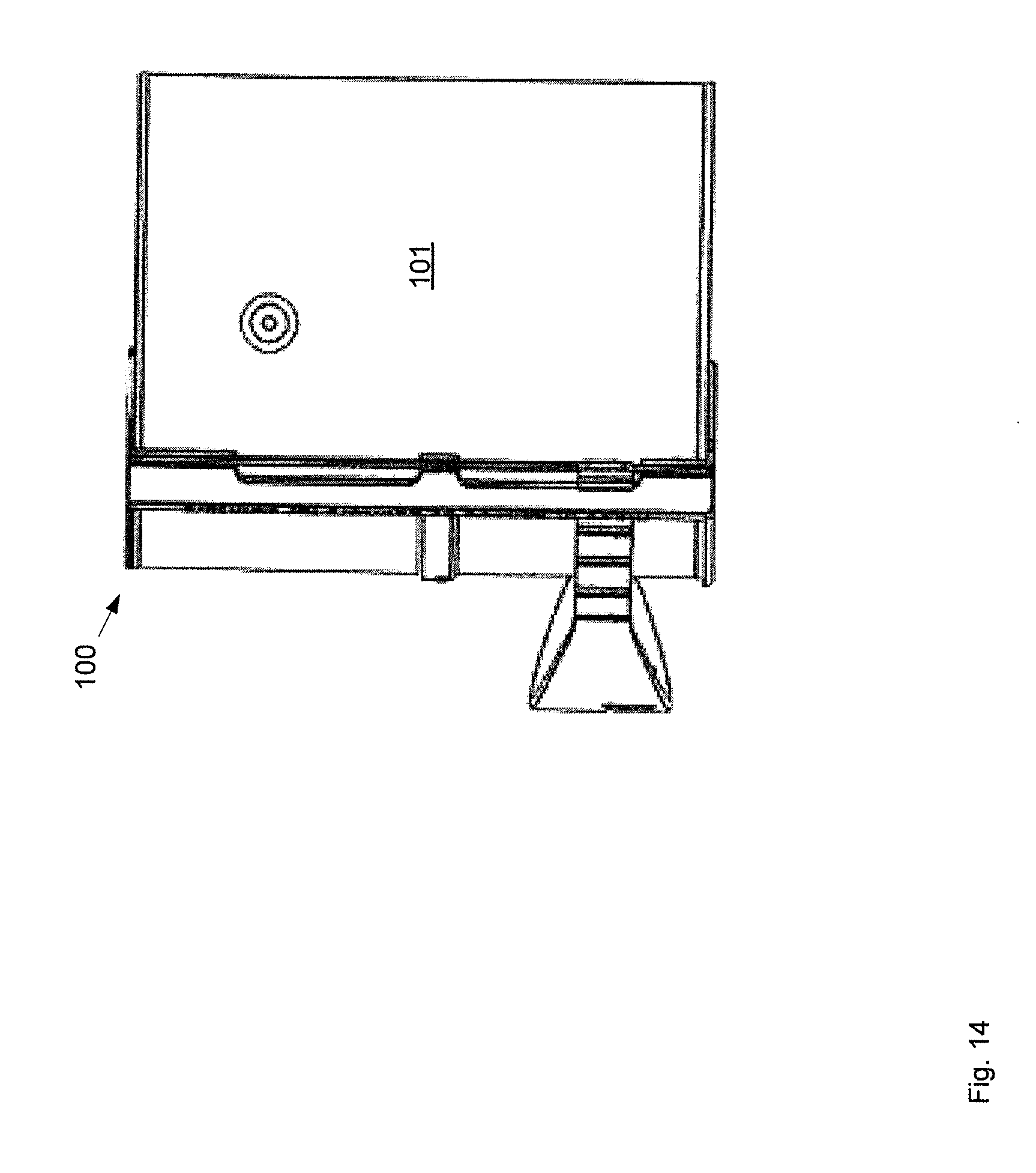
D00015

D00016

D00017

D00018
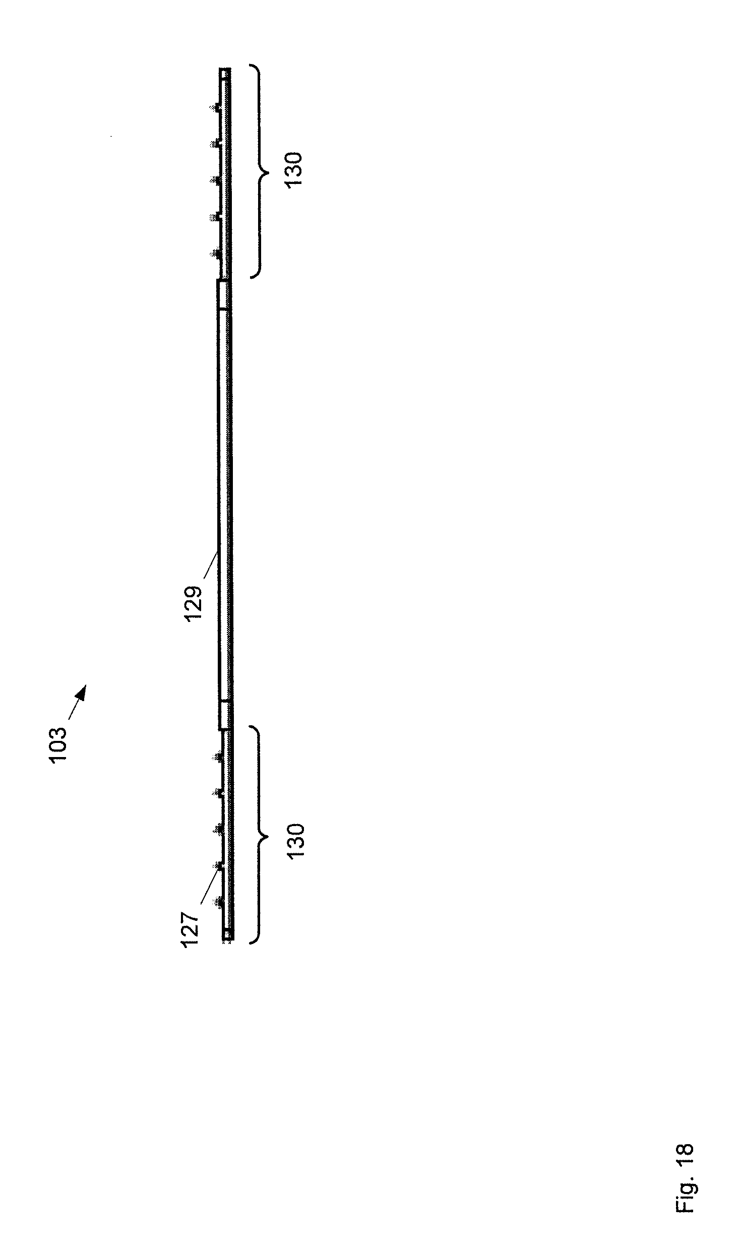
D00019
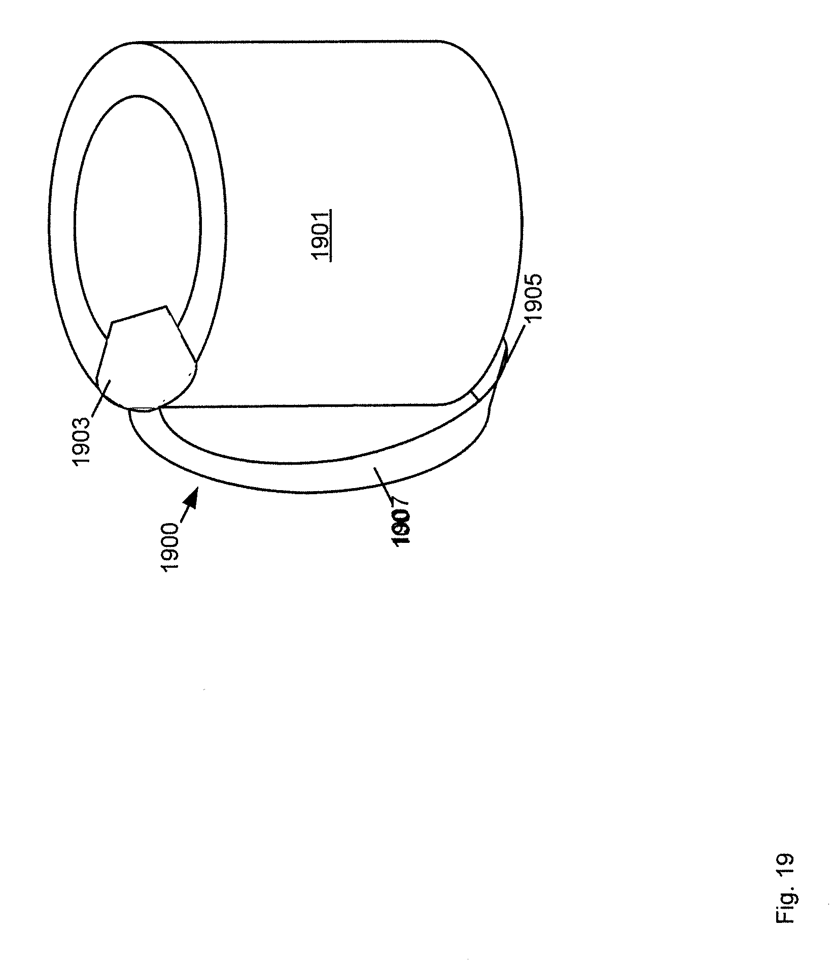
D00020
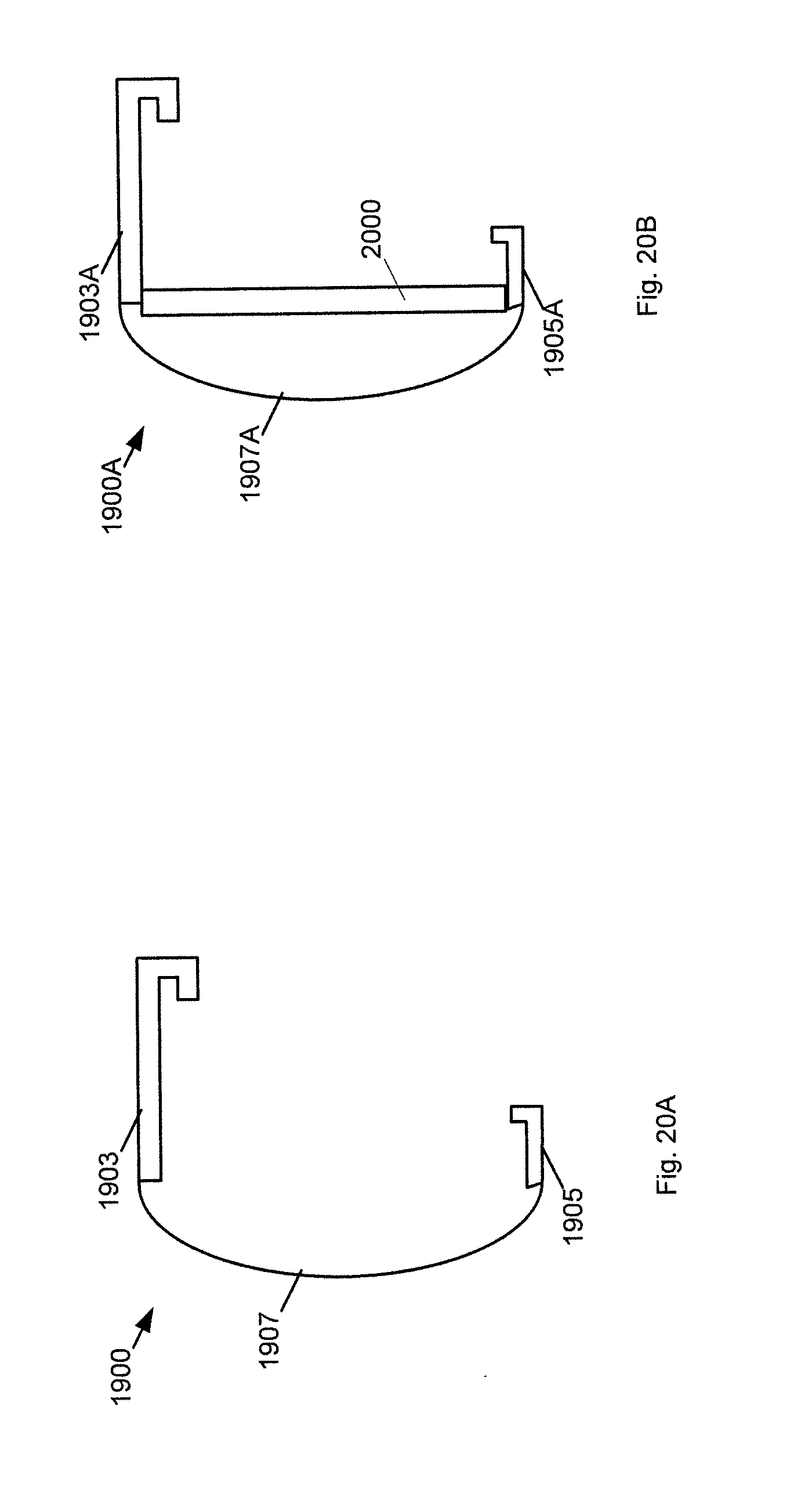
D00021
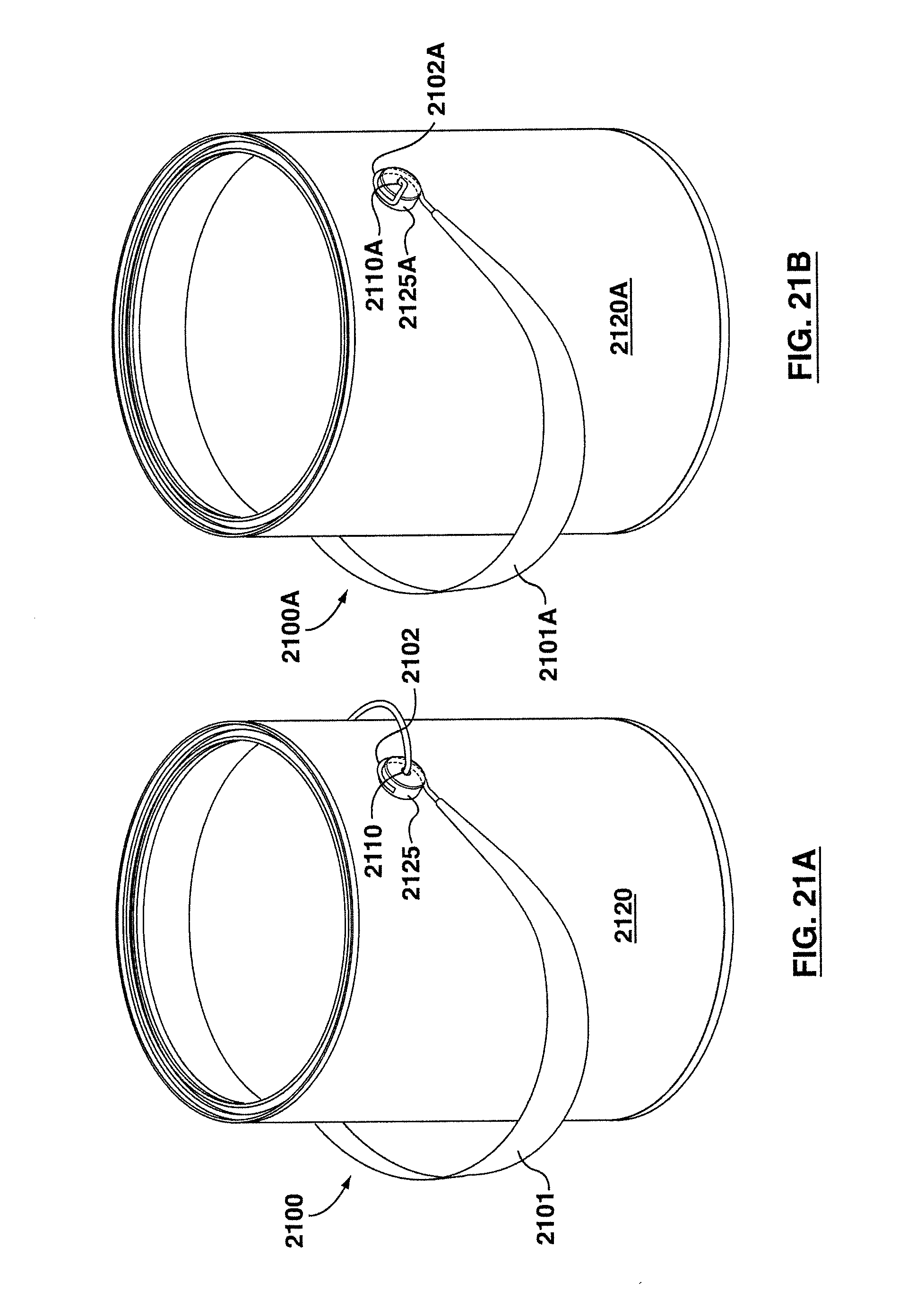
D00022

D00023

D00024

D00025

D00026

D00027
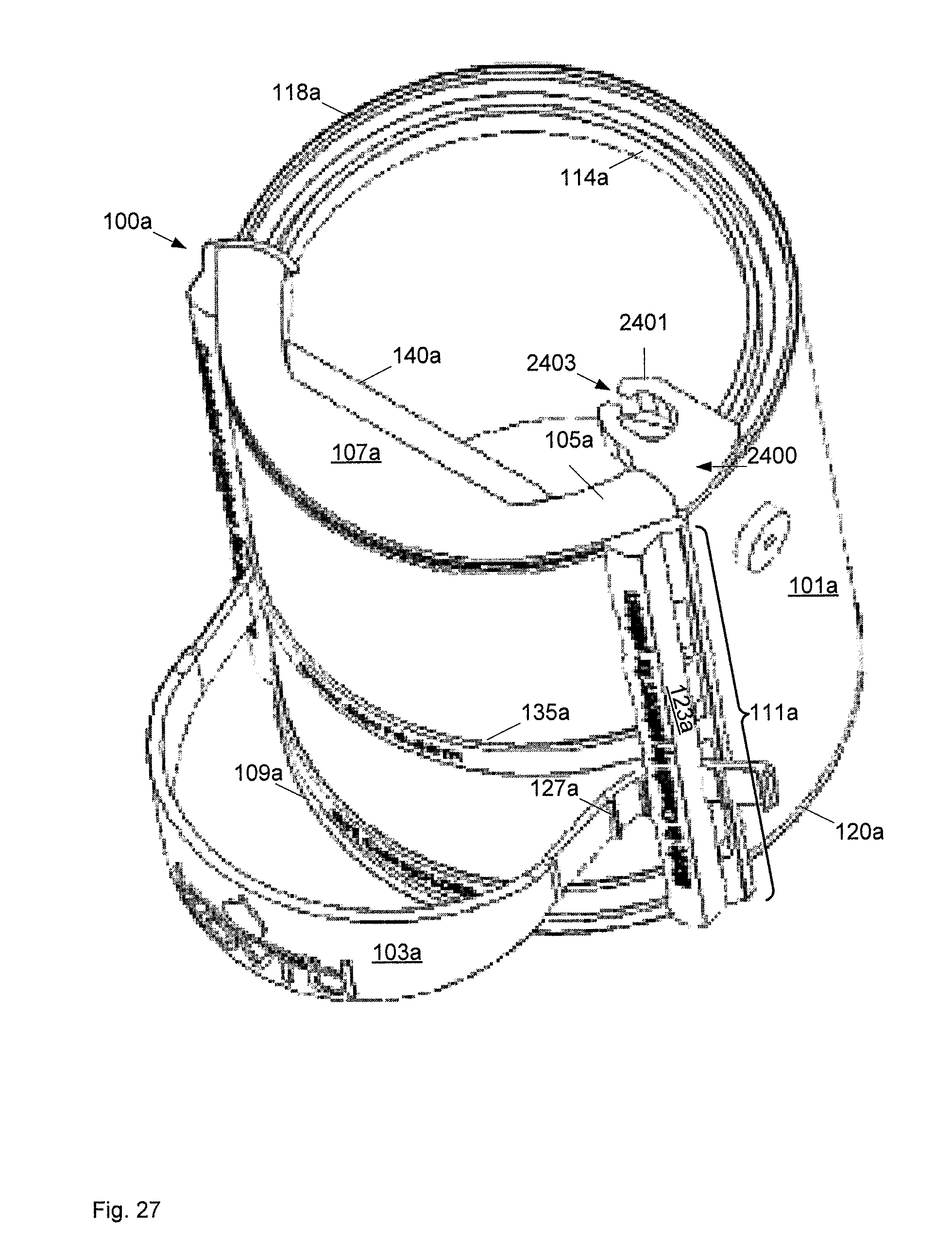
D00028

D00029

D00030
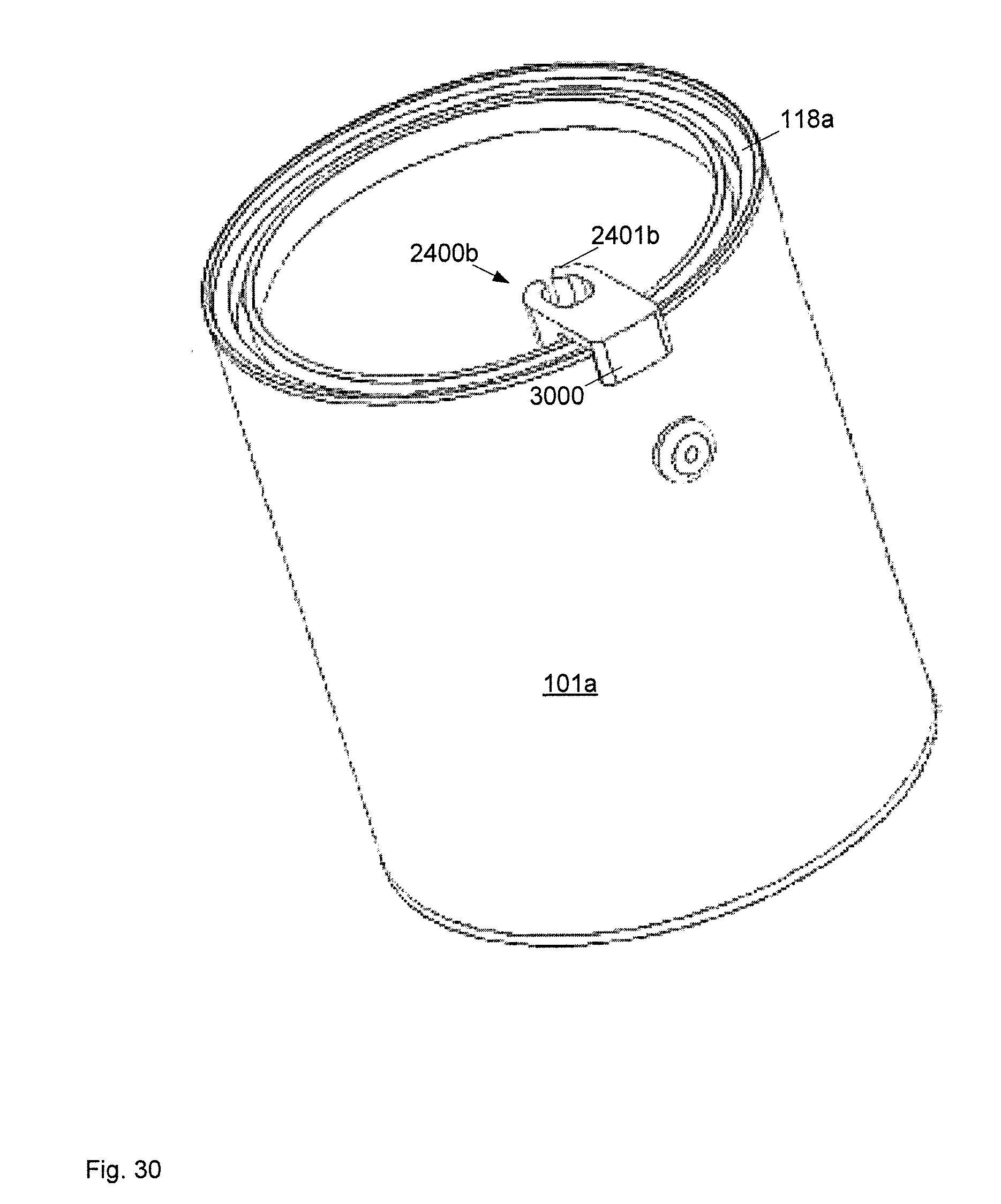
D00031
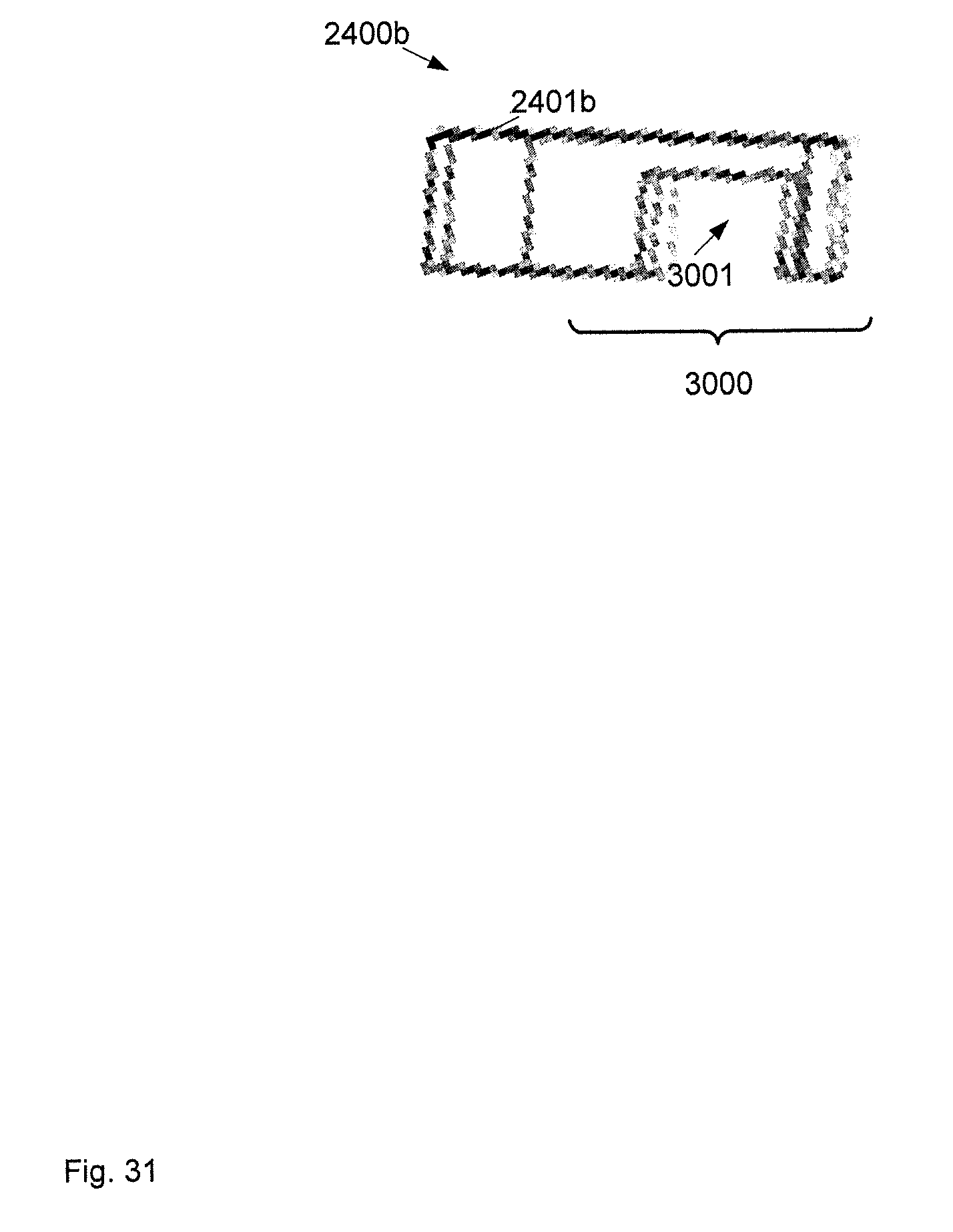
D00032

D00033

D00034

D00035

D00036
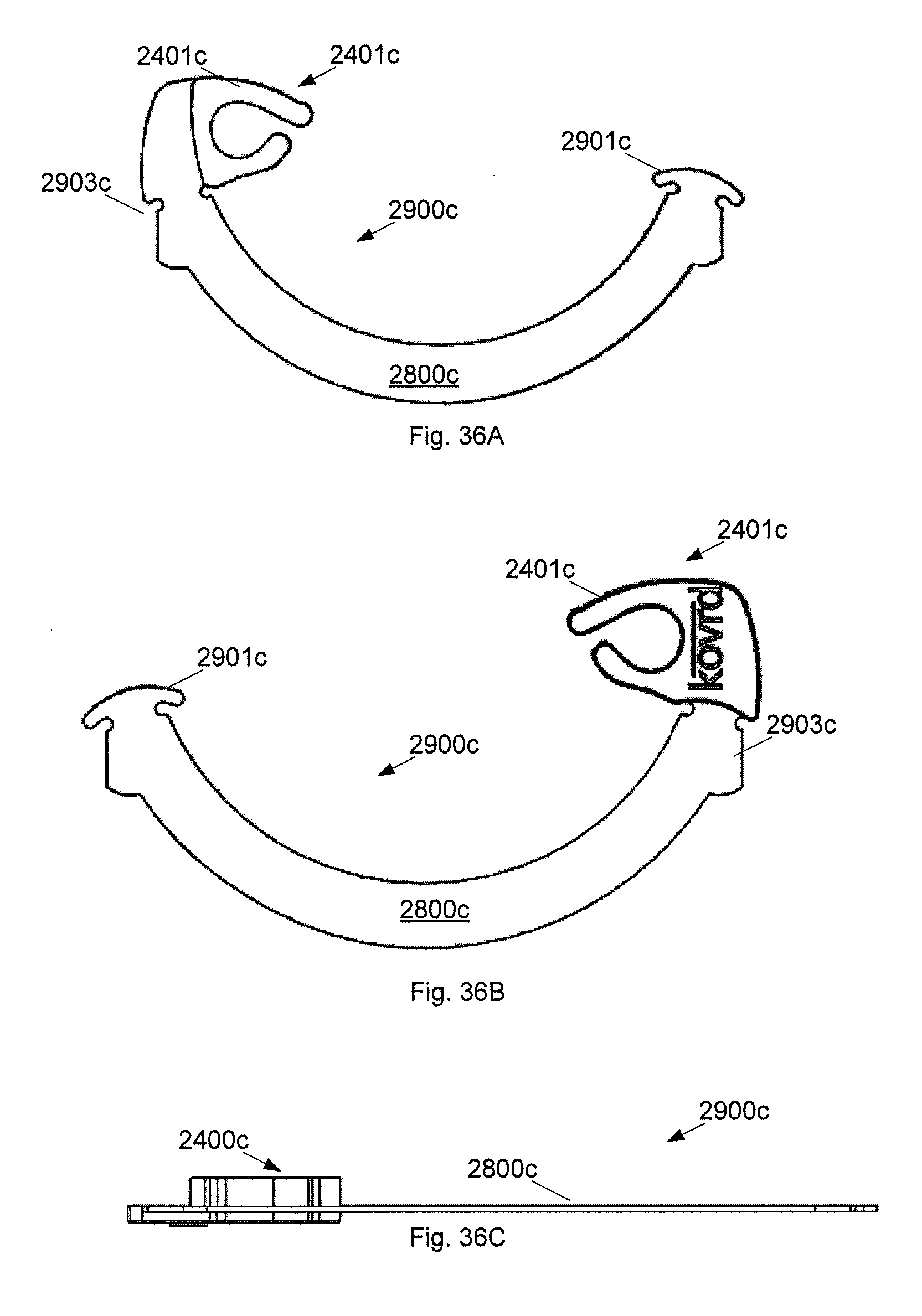
D00037

D00038

D00039
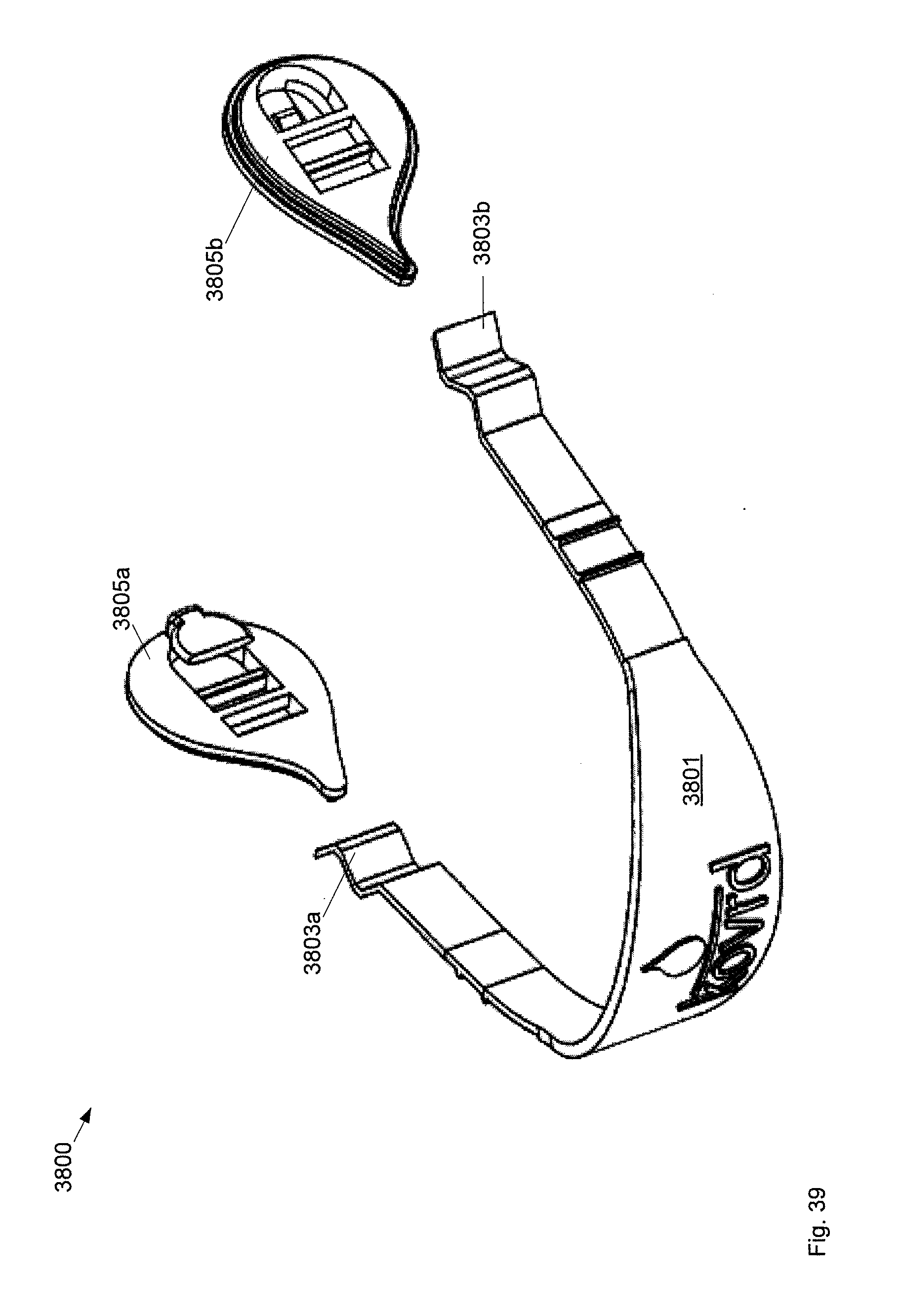
D00040
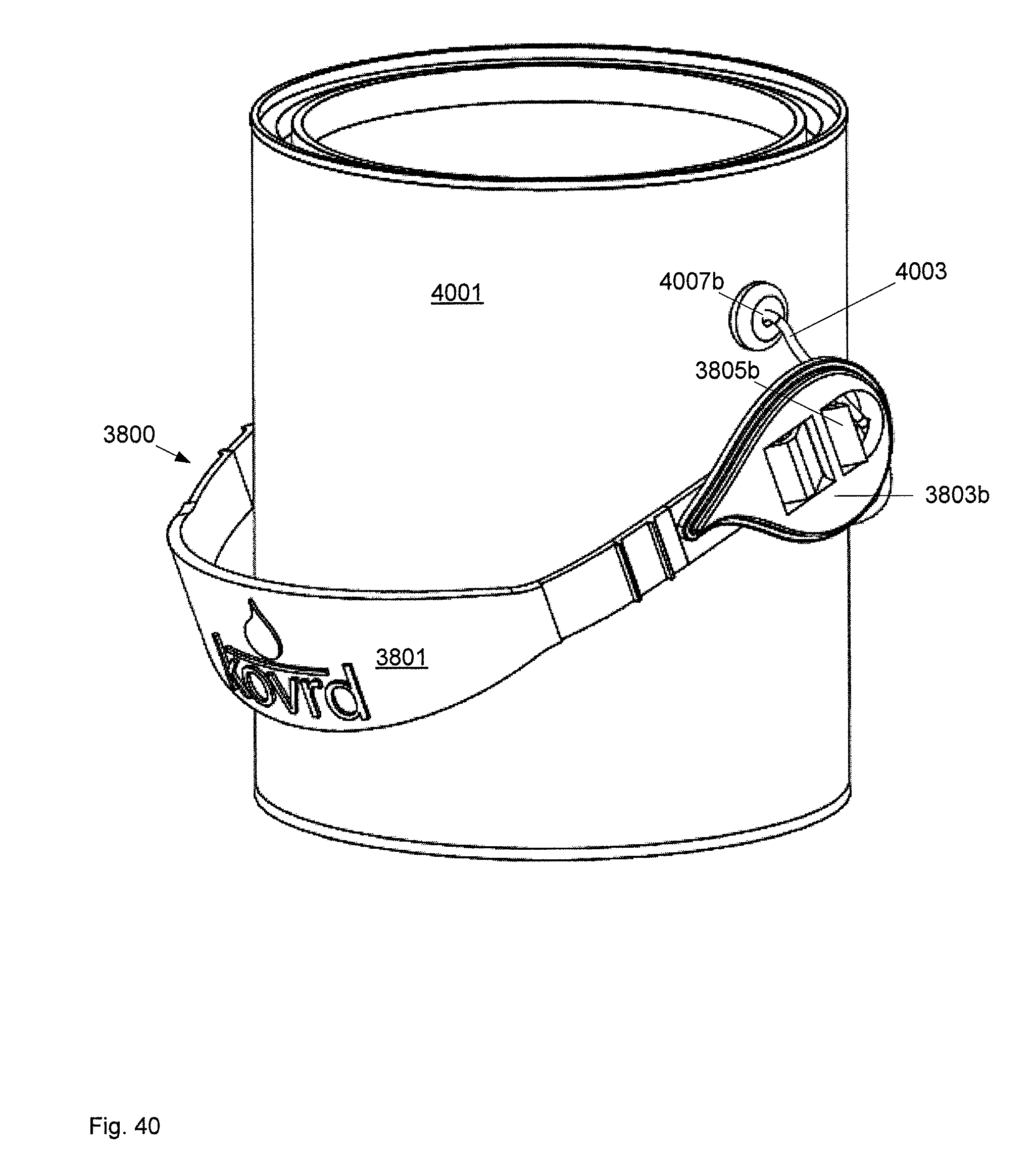
D00041
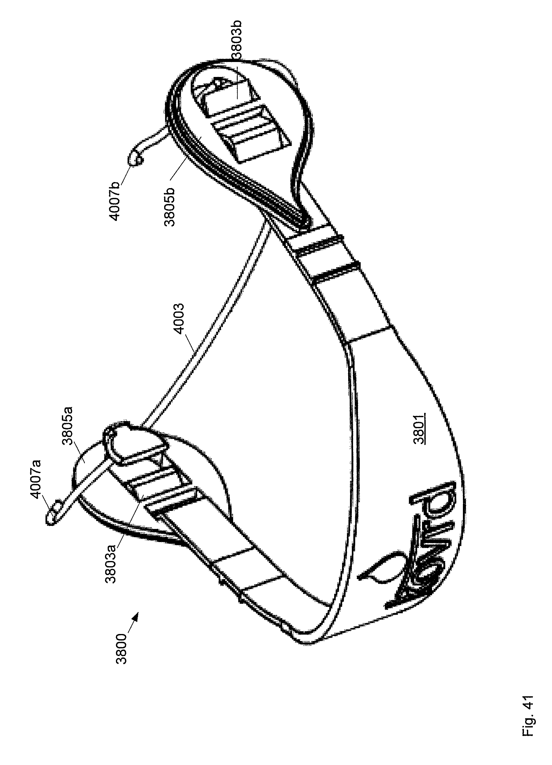
D00042
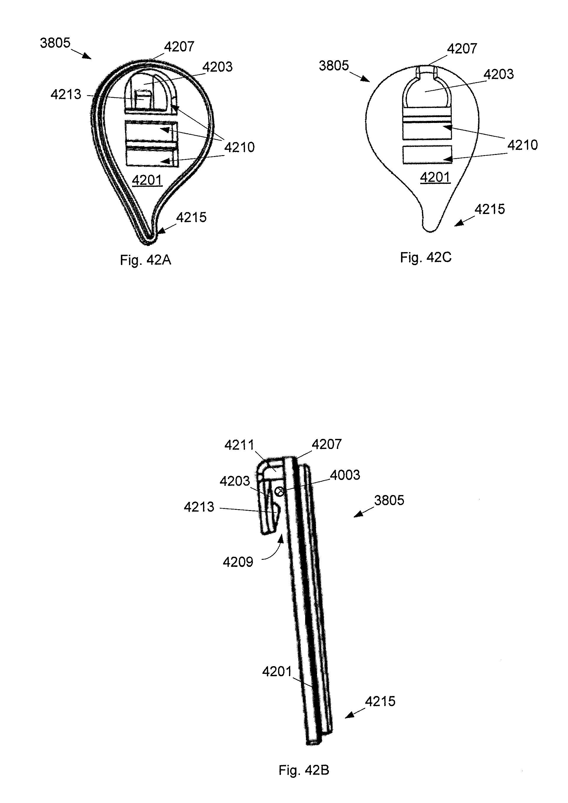
D00043

D00044

D00045
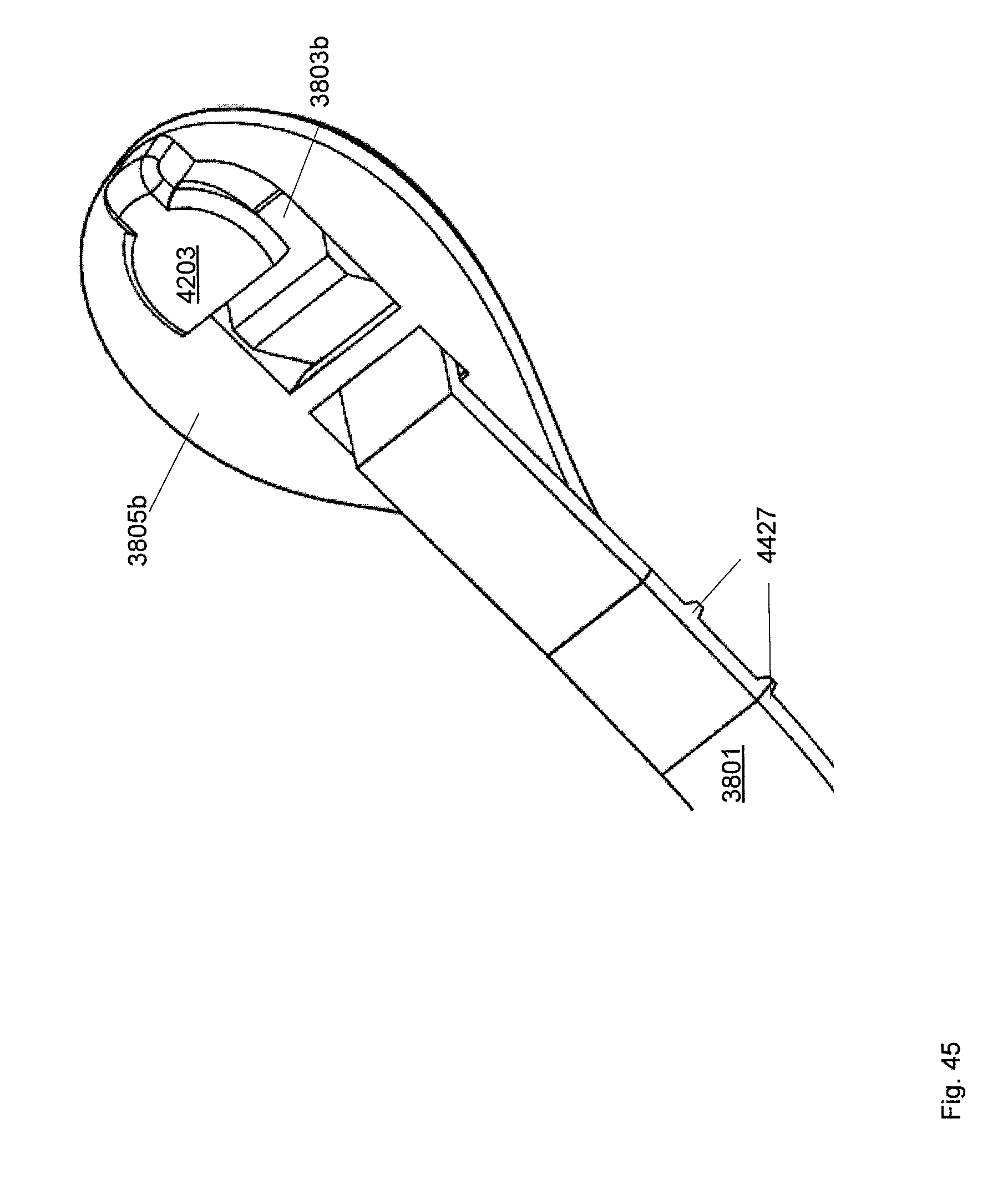
D00046

D00047

D00048

D00049

XML
uspto.report is an independent third-party trademark research tool that is not affiliated, endorsed, or sponsored by the United States Patent and Trademark Office (USPTO) or any other governmental organization. The information provided by uspto.report is based on publicly available data at the time of writing and is intended for informational purposes only.
While we strive to provide accurate and up-to-date information, we do not guarantee the accuracy, completeness, reliability, or suitability of the information displayed on this site. The use of this site is at your own risk. Any reliance you place on such information is therefore strictly at your own risk.
All official trademark data, including owner information, should be verified by visiting the official USPTO website at www.uspto.gov. This site is not intended to replace professional legal advice and should not be used as a substitute for consulting with a legal professional who is knowledgeable about trademark law.