Bulk Packaging Container
Meints; Scott T. ; et al.
U.S. patent application number 13/172414 was filed with the patent office on 2011-12-29 for bulk packaging container. This patent application is currently assigned to Hoover Materials Handling Group, Inc.. Invention is credited to Michael Dean Hartley, Scott T. Meints.
| Application Number | 20110315689 13/172414 |
| Document ID | / |
| Family ID | 45351562 |
| Filed Date | 2011-12-29 |


| United States Patent Application | 20110315689 |
| Kind Code | A1 |
| Meints; Scott T. ; et al. | December 29, 2011 |
Bulk Packaging Container
Abstract
A dual tank bulk packaging container comprises an inner receptacle comprising a peripheral wall between opposite top and bottom walls to define a primary containment space. The inner receptacle comprises an outlet proximate a bottom end thereof. An outer shell comprises a peripheral sidewall connected to a formed bottom to define a secondary containment space having an upper opening sized to receive the inner receptacle. The outer shell includes integral legs for resting on a support surface. The peripheral sidewall is configured to support the inner receptacle in the secondary containment space. The outer shell comprises an outlet proximate a bottom end thereof wherein the inner receptacle outlet is aligned with the outer shell outlet incident to the inner receptacle being received in the outer shell. A seal is provided between the inner receptacle and the outer shell proximate the outlets thereof.
| Inventors: | Meints; Scott T.; (Katy, TX) ; Hartley; Michael Dean; (Beatrice, NE) |
| Assignee: | Hoover Materials Handling Group,
Inc. |
| Family ID: | 45351562 |
| Appl. No.: | 13/172414 |
| Filed: | June 29, 2011 |
Related U.S. Patent Documents
| Application Number | Filing Date | Patent Number | ||
|---|---|---|---|---|
| 61359478 | Jun 29, 2010 | |||
| Current U.S. Class: | 220/500 |
| Current CPC Class: | B65D 90/00 20130101; B65D 2588/125 20130101; B65D 90/0033 20130101; B65D 25/54 20130101; B65D 77/0486 20130101; B65D 90/20 20130101; B65D 21/0215 20130101; B65D 88/022 20130101 |
| Class at Publication: | 220/500 |
| International Class: | B65D 25/04 20060101 B65D025/04 |
Claims
1. A dual tank bulk packaging container comprising: an inner receptacle comprising a peripheral wall between opposite top and bottom walls to define a primary containment space, the inner receptacle comprising an outlet proximate a bottom end thereof; an outer shell comprising a peripheral sidewall connected to a formed bottom to define a secondary containment space having an upper opening sized to receive the inner receptacle, the outer shell including integral legs for resting on a support surface, the peripheral sidewall being configured to support the inner receptacle in the secondary containment space, the outer shell comprising an outlet proximate a bottom end thereof wherein the inner receptacle outlet is aligned with the outer shell outlet incident to the inner receptacle being received in the outer shell; and a seal between the inner receptacle and the outer shell proximate the outlets thereof.
2. The dual tank bulk packaging container of claim 1 wherein the inner receptacle peripheral wall is generally cylindrical.
3. The dual tank bulk packaging container of claim 2 wherein the inner receptacle peripheral wall is between about 18 and 68 inches diameter.
4. The dual tank bulk packaging container of claim 1 wherein the outer shell peripheral sidewall comprises a generally cylindrical shape having four integral corner supports radially outwardly thereof, wherein bottom ends of the corner supports define the integral legs.
5. The dual tank bulk packaging container of claim 4 wherein top and bottom ends of the corner supports are closed and formed to enable stacking of multiple dual tank bulk packaging containers.
6. The dual tank bulk packaging container of claim 5 wherein the corner supports have upper openings to define sling points.
7. The dual tank bulk packaging container of claim 4 wherein the corner supports are located radially outwardly of the secondary containment space upper opening.
8. The dual tank bulk packaging container of claim 1 wherein the outer shell comprises a sight window integrally molded in a vertical opening in the peripheral sidewall.
9. The dual tank bulk packaging container of claim 1 wherein the formed bottom comprises fork pockets for handling by a forklift.
10. The dual tank bulk packaging container of claim 1 wherein the seal comprises a bellows operatively connected between the outer shell and the inner receptacle.
11. A bulk packaging container comprising: a plastic inner receptacle comprising a cylindrical wall between opposite top and bottom walls to define a primary containment space, the top wall having a fill opening, and the bottom wall being generally dome shaped and having a discharge outlet; a plastic one piece outer shell comprising a peripheral sidewall connected to a formed bottom to define a secondary containment space having an upper circular opening sized to receive the inner receptacle, the outer shell including integral legs for resting on a support surface, the peripheral sidewall being configured to support the inner receptacle in the secondary containment space, the outer shell comprising an outlet opening proximate a bottom end thereof wherein the inner receptacle discharge outlet is aligned with the outer shell outlet opening incident to the inner receptacle being received in the outer shell; and a seal between the inner receptacle and the outer shell proximate the outlet opening.
12. The bulk packaging container of claim 11 wherein the inner receptacle cylindrical wall is between about 18 and 68 inches diameter.
13. The bulk packaging container of claim 11 wherein the outer shell peripheral sidewall comprises a generally cylindrical shape having four integral corner supports radially outwardly thereof, wherein bottom ends of the corner supports define the integral legs.
14. The bulk packaging container of claim 13 wherein top and bottom ends of the corner supports are closed and formed to enable stacking of multiple dual tank bulk packaging containers.
15. The bulk packaging container of claim 14 wherein top ends of the corner supports include nipples and the bottom ends of the corner posts include blind bores for interlocking with nipples of a subjacent bulk packaging containers for stability when stacking.
16. The bulk packaging container of claim 15 wherein the corner supports have upper openings to define sling points.
17. The bulk packaging container of claim 13 wherein the corner supports are located radially outwardly of the secondary containment space upper opening.
18. The bulk packaging container of claim 11 wherein the outer shell comprises a sight window integrally molded in a vertical opening in the peripheral sidewall.
19. The bulk packaging container of claim 11 wherein the formed bottom comprises fork pockets for handling by a forklift.
20. The bulk packaging container of claim 11 wherein the seal comprises a bellows operatively connected between the outer shell and the inner receptacle.
Description
CROSS-REFERENCE TO RELATED APPLICATIONS
[0001] This application claims priority of provisional application No. 61/359,478 filed Jun. 29, 2010.
FEDERALLY SPONSORED RESEARCH OR DEVELOPMENT
[0002] Not Applicable.
MICROFICHE/COPYRIGHT REFERENCE
[0003] Not Applicable.
FIELD OF THE INVENTION
[0004] The present invention relates to a bulk packaging container including an inner plastic receptacle for containing a fluid product and an outer plastic one piece shell for support and secondary containment.
BACKGROUND OF THE INVENTION
[0005] Bulk packaging containers have found widespread use for storage and shipment of bulk goods. The bulk packaging containers assume many different forms. Among these forms are portable tanks and intermediate bulk containers (IBC). Requirements for these types of containers are outlined in various D.O.T. and F.D.A. regulations and are particularly defined in 49CFR Section 171.8.
[0006] Among IBC's, there are numerous types of designs. These include metal designs, which are constructed of metal, rigid plastic IBC's which are constructed of all-plastic material, and composite IBC's which include a rigid outer package enclosing a plastic inner receptacle.
[0007] An IBC typically has a capacity in the range of 250-550 gallons. Some are as small as 119 gallons and as large as 793 gallons. As such, they are an efficient alternative to 55-gallon drums. Nevertheless, each IBC must be handled and transported individually when used, for example, in the export of materials. The IBC is typically loaded into a shipping vessel, transport vehicle, or transport trailer. Each IBC must be individually slung by a crane or carried by a forklift during the loading or unloading.
[0008] There is a desire to minimize weight of the bulk packaging container, while ensuring that the bulk packaging container is of sufficient strength to hold its contents during both storage and transportation. In this regard, designs of IBCs have transitioned from use of metal to more use of plastic. These include the noted composites IBC's including a rigid outer packaging enclosing a plastic inner receptacle. In any such design, the outer packaging must be capable of withstanding handling such as by forklift and or slings. With any such design there is always the possibility that the inner receptacle becomes breached. If this were to occur, then the contents of the container would leak out and be lost and possibly damage other products.
[0009] It is therefore desirable to provide an IBC of sufficient strength and design to minimize the likelihood of breach, but while being adapted to contain the contents of the receptacle in the event of a breach.
[0010] The present invention is directed to overcoming one or more of the problems discussed above, in a novel and simple manner.
SUMMARY OF THE INVENTION
[0011] In accordance with the invention, there is provided a dual tank bulk packaging container which provides for secondary containment.
[0012] There is disclosed in accordance with one aspect of the invention a dual tank bulk packaging container comprising an inner receptacle comprising a peripheral wall between opposite top and bottom walls to define a primary containment space. The inner receptacle comprises an outlet proximate a bottom end thereof. An outer shell comprises a peripheral sidewall connected to a formed bottom to define a secondary containment space having an upper opening sized to receive the inner receptacle. The outer shell includes integral legs for resting on a support surface. The peripheral sidewall is configured to support the inner receptacle in the secondary containment space. The outer shell comprises an outlet proximate a bottom end thereof wherein the inner receptacle outlet is aligned with the outer shell outlet incident to the inner receptacle being received in the outer shell. A seal is provided between the inner receptacle and the outer shell proximate the outlets thereof.
[0013] It is a feature of the invention that the inner receptacle peripheral wall is generally cylindrical. The inner receptacle peripheral wall may be between about 18 and 68 inches in diameter.
[0014] It is another feature of the invention that the outer shell peripheral sidewall comprises a generally cylindrical shape having four integral corner supports radially outwardly thereof. Bottom ends of the corner supports define the integral legs. Top and bottom ends of the corner supports are closed and may be formed to enable stacking of multiple dual tank bulk packaging containers. The corner supports may have upper openings to define sling points. The corner supports may be located radially outwardly of the secondary containment space upper opening.
[0015] It is a further feature of the invention that the outer shell comprises a sight window integrally molded in a vertical opening in the peripheral sidewall.
[0016] It is yet another feature of the invention that the formed bottom comprises fork pockets for handling by a fork lift.
[0017] It is still another feather of the invention to provide a seal in the form of a bellows operatively connected between the outer shell and the inner receptacle.
[0018] There is disclosed in accordance with another aspect of the invention a bulk packaging container comprising a plastic inner receptacle and a plastic one piece outer shell. The inner receptacle comprises a cylindrical wall between opposite top and bottom walls to define a primary containment space. The top wall has a fill opening. The bottom wall is generally dome-shaped and has a discharge outlet. The outer shell comprises a peripheral sidewall connected to a formed bottom to define a secondary containment space having an upper circular opening sized to receive the inner receptacle. The outer shell includes integral legs for resting on a support surface. The peripheral sidewall is configured to support the inner receptacle in the secondary containment space. The outer shell comprises an outlet opening proximate a bottom end thereof wherein the inner receptacle discharge outlet is aligned with the outer shell outlet opening incident to the inner receptacle being received in the outer shell. A seal is provided between the inner receptacle and the outer shell proximate the outlet opening.
[0019] Other objects, features, and advantages of the invention will become apparent from a review of the entire specification, including the appended claims and drawings.
BRIEF DESCRIPTION OF THE DRAWINGS
[0020] FIG. 1 is a perspective view of a dual tank bulk packaging container in accordance with the invention;
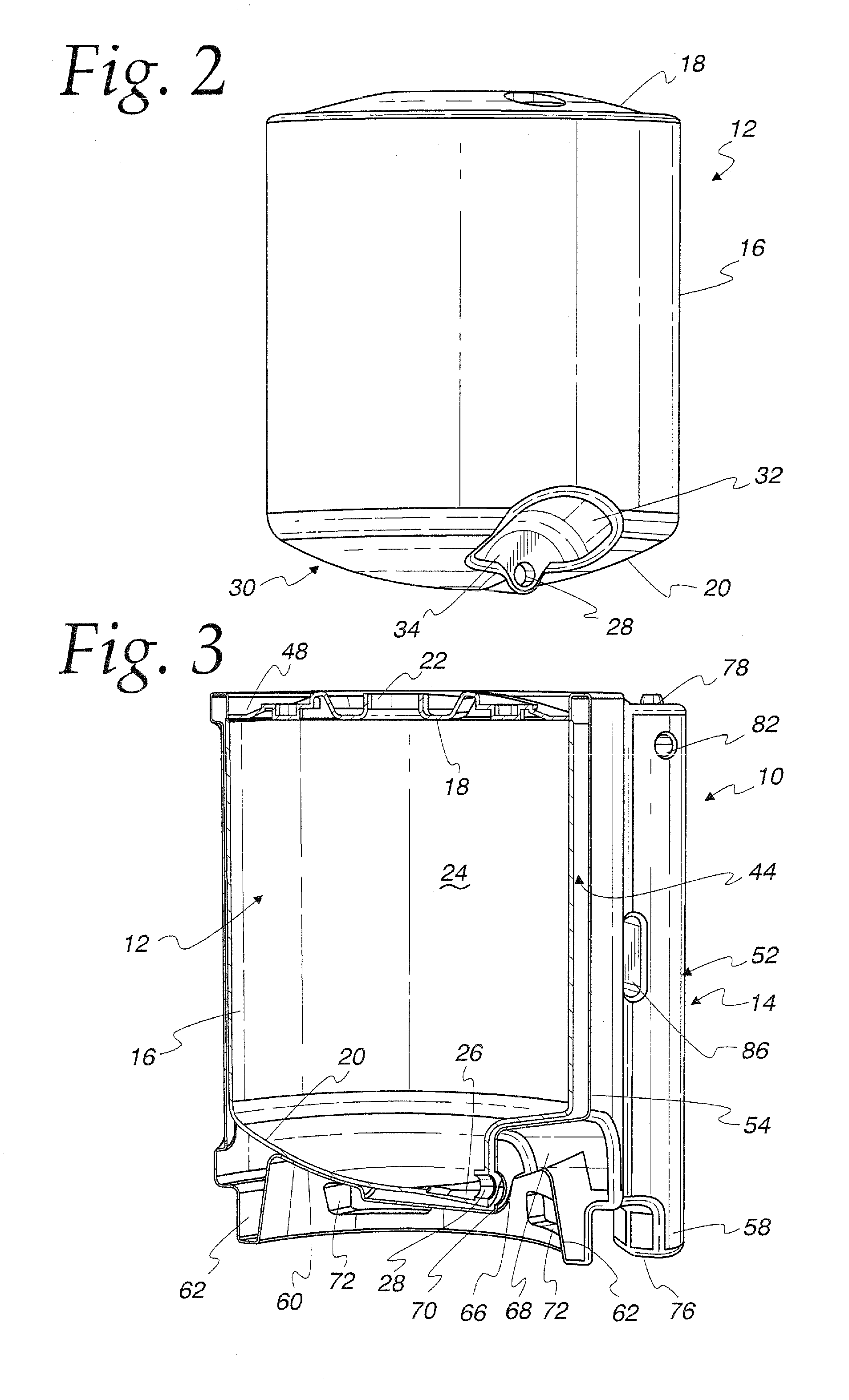
[0021] FIG. 2 is a perspective view of an inner plastic receptacle of the dual tank bulk packaging container of FIG. 1;
[0022] FIG. 3 is a perspective sectional view taken along the line 3-3 of FIG. 1;
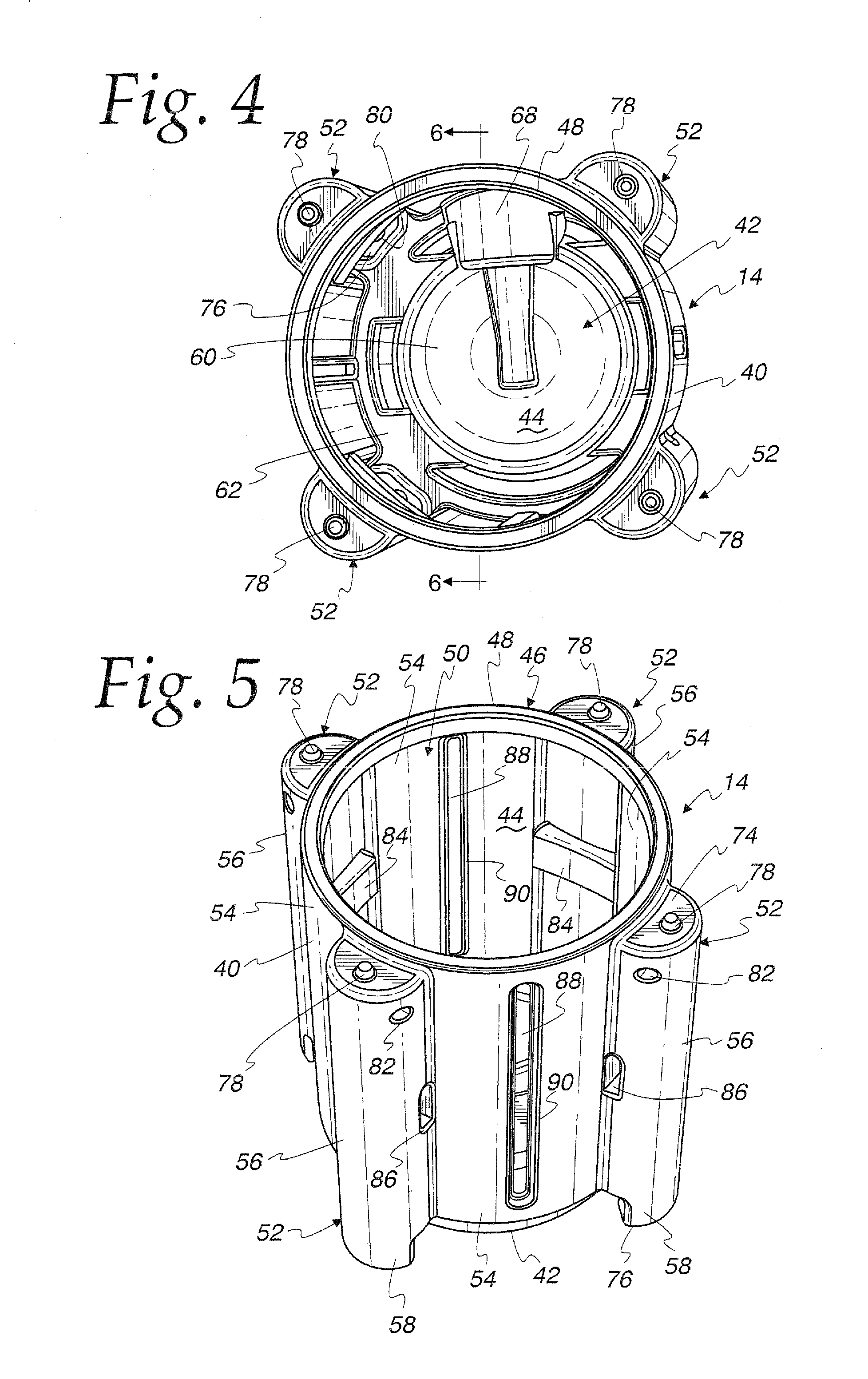
[0023] FIG. 4 is a top perspective view of the outer plastic shell of the dual tank bulk packaging container of FIG. 1;
[0024] FIG. 5 is a perspective view of the outer plastic shell;
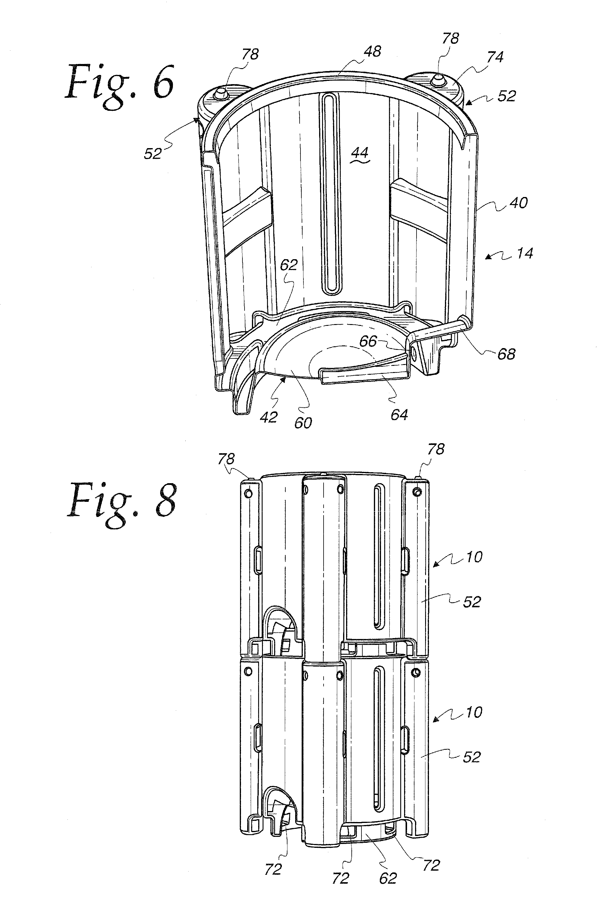
[0025] FIG. 6 is a side perspective sectional view of the outer plastic shell;
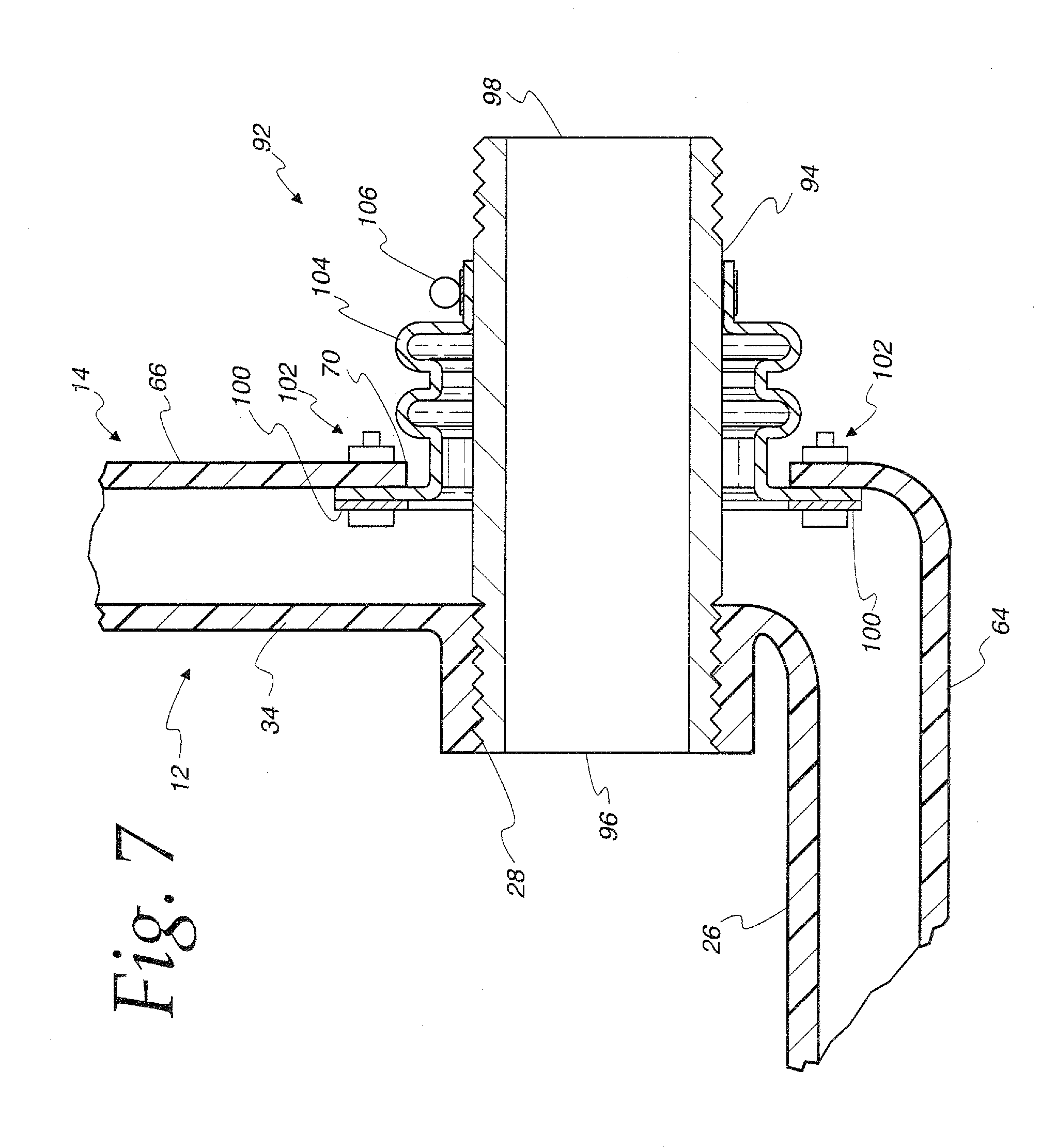
[0026] FIG. 7 is a detailed section showing a seal between the inner plastic receptacle and the outer plastic shell; and
[0027] FIG. 8 is an elevation view showing a pair of stacked bulk packaging containers.
DETAILED DESCRIPTION OF THE PREFERRED EMBODIMENT
[0028] Referring to FIG. 1, a dual tank bulk packaging container 10 in accordance with the invention is illustrated. The container 10 comprises an inner receptacle 12 and an outer shell or body 14. The inner receptacle 12 provides for primary containment, while the outer shell 14 provides for secondary containment, as described more specifically below.
[0029] Referring also to FIG. 2, the inner receptacle 12 comprises a cylindrical, peripheral wall 16 between a top wall 18 and an opposite bottom wall 20. The top wall 18 is formed to include a central fill opening 22 that can be selectively closed by a closure (not shown) to provide entry to a primary containment space 24, see FIG. 3. The bottom wall 20 is generally an inverted dome shape including a sump 26 communicating with a discharge outlet 28 to provide for complete drainage from the primary containment space 24. The discharge outlet 28 is provided at a bottom end 30 of the inner receptacle 12. A semi-cylindrical wall 32 extends radially inwardly from the peripheral wall 16 at the bottom end 30 and is generally coaxial with the discharge outlet 28. An inner end of the semi-cylindrical wall 32 is closed by a planar wall portion 34 connected to the dome bottom wall 20. The discharge outlet 28 is in the planar wall 34. The semi-cylindrical wall 32 provides an area for connection to suitable valves and the like while protecting the same from damage. Particularly, this structure places the discharge outlet 28 inset from the peripheral wall 16.
[0030] The inner receptacle 12 is rotationally molded and is thus unitarily formed of one piece plastic construction. The inner receptacle 12 is formed or molded using a plastic resin material. Particularly, the receptacle 12 is durable and can withstand extreme surface environments and harsh outdoor weather. The receptacle 12 is rotationally molded to form a seamless, one-piece plastic tank that will not leak, rust, chip or corrode. Typically, the inner receptacle 12 would be formed of linear load density polyethylene. However, the container could be formed of other materials. Likewise, the inner receptacle 12 could be of a shape other than cylindrical, as will be apparent. The inner receptacle 12 will generally be 18'' to 68'' in diameter, have a height varying from 24'' to 112'', and have a uniform wall thickness of 1/16'' thick to 1'' thick. As such, the inner receptacle may have a capacity in the range of about 250-550 gallons.
[0031] Referring to FIGS. 4-6, the outer shell 14 comprises a peripheral sidewall 40 connected to a formed bottom 42 to define a secondary containment space 44. The peripheral wall 40 at a top end 46 includes a circular rim 48 defining a circular opening 50 into the secondary containment space 44. The circular opening 50 is sized to receive the inner receptacle 12, as illustrated in FIGS. 1 and 3.
[0032] The peripheral sidewall 40 is continuous surrounding the secondary containment space 44 and is generally cylindrical shape having four integral corner supports or posts 52. Particularly, the peripheral sidewall 40 comprises curved wall portions 54 between each corner post 52. The curved wall portions 54 are coaxial with and have a radius slightly larger than the radius of the circular opening 50. The corner posts 52 comprise semi-cylindrical walls 56 of a significantly smaller radius. Each curved wall portion 54 is of a size to extend between two adjacent corner posts 56 and is bounded at its top by the rim 48 and at its bottom by the formed bottom 42. The corner supports 52 extend downwardly below the formed bottom 42 to define integral legs 58 for resting on a support surface.
[0033] The formed bottom 42 comprises a dome shaped or spherical wall 60 surrounded by a circular trough 62. In use, the feet 58 rest on an appropriate support surface, as does the trough 62. A sump 64 is provided extending radially outwardly from a center of the dome shaped wall 60 and ends at a vertical planar wall 66. A radially outwardly extending semi-cylindrical wall 68, of a size adapted to be received in the inner receptacle semi-cylindrical wall 32, as shown in FIG. 3, extends from the planar wall 66 to a bottom of one of the curved wall portions 54. An outlet opening 70 is provided in the planar wall 66. The trough 62 includes four fork pockets 72, three of which are shown in FIG. 7, adapted to receive tines of a fork lift.
[0034] Each corner post 52 is closed at a top wall 74 and an opposite bottom wall 76. The top wall 74 includes an upwardly extending nipple 78. The bottom wall 76 includes a matching downwardly opening receptacle 80, an inside of which is shown in FIG. 4, for interlocking with a subjacent nipple 78 for stacking. Each corner post 52 includes opposite upper openings 82 which can be used for lifting and transporting the container by overhead crane. The cylindrical openings 82 can be reinforced using metal pipe or other materials to assist in lifting heavy loads. A rectangular tube beam 84 is centrally located and extends horizontally across each support 52 and is open at opposite sides as shown at 86. The tube beams 84 provide additional strength and reinforcement.
[0035] As described, the secondary containment space 44 is entirely enclosed except for the upper opening 50 and the outlet opening 70. The corner posts 52 are hollow and thus form part of the secondary containment space 44. The outer shell 14 is formed or molded using a plastic resin material. The outer shell 14 may be rotationally molded and formed of a polyethylene including both virgin material and regrind or the like. The outer plastic one piece shell 14 will generally have a base dimension ranging from 24.times.24'' up to 72''.times.72'', a height varying from 26'' to 100'', and have a uniform wall thickness of 1/16'' thick to 1/2'' thick. Advantageously, one or more sight windows 88 of Plexiglas or the like are integrally molded in vertical openings 90 in one or more of the peripheral sidewall curved wall portions 54. The molded in sight windows 88 provide for viewing the fluid contents that are inside the inner plastic receptacle 12.
[0036] For use, the inner receptacle 12 is lowered downwardly through the outer shell opening 50 into the secondary containment space 44 as shown in FIGS. 1 and 3. The receptacle bottom wall 20 is supported on the shell bottom wall 60. The interaction between the receptacle cylindrical wall 32 and the shell cylindrical wall 68 provides appropriate alignment of the inner receptacle 12 and properly aligns the discharge outlet 28 relative to the outlet opening 70 incident to the inner receptacle 12 being received in the outer shell 14, as shown.
[0037] Referring to FIG. 7, a seal 92 is provided between the inner receptacle 12 and the outer shell 14 proximate the outlets 28 and 70, respectively, thereof. The seal 92 includes an elongate threaded nipple 94 having an inner end 96 threaded into the inner receptacle discharge outlet 28. An outer end 98 of the threaded nipple 94 extends out through the outer shell outlet opening 70 for connection to a valve or hose, not shown, in use. An annular clamp plate 100 is connected to the outer shell planar wall 66 using fasteners 102 to connect a flexible rubber bellows 104 surrounding the threaded nipple 94. A hose clamp 106 connects an outer end of the bellows 104 to the threaded nipple 94. As such, the bellows 104 provides a sealed connection between the outer shell 14 and the threaded nipple 94, and thus also the inner receptacle 12.
[0038] Should a breach occur in the inner receptacle 12, the secondary containment space 44 of the outer shell 14 will contain any material that escapes from the inner receptacle 12.
[0039] Typically, the dual tank bulk packaging container 10 is supported on a ground surface. Alternatively, due to space restrictions, it may be necessary to stack the bulk packaging containers 10, as shown in FIG. 8. In this instance, the corner posts 52 function as vertical beams with the corner posts 52 of an uppermost container 10 being on the corner posts 52 of a subjacent container 10. The containers 10 are interlocked relative to one another by the nipples 78 of a lowermost container 10 being received in the downwardly opening receptacles 80 in the uppermost container 10, as described.
[0040] The inner plastic receptacle top wall 18 may be of a domed shaped and include openings for filling and or discharging. The inner plastic receptacle bottom wall 20 may also be of a domed shaped with formations to assist with complete drainage. The inner plastic receptacle bottom wall 20 also includes the outlet 28 for discharging contents.
[0041] The outer plastic one piece shell 14 is of a generally cylindrical design with four vertical corner supports 52 molded as one unit. The corner supports 52 provide strength and stability when double stacking the containers 10 one on top of the other and also the mechanism to add sling points using the openings 82. The formed bottom 42 of the outer plastic one piece shell 14 interlocks with the top portion of the outer plastic one piece shell 14 to provide stability when double stacking the containers 10.
[0042] The top and bottom of the outer plastic one piece shell 14 are designed as such so the outer plastic one piece shell 14 does not come in contact with the inner plastic receptacle 12 of a subjacent container 10 when double stacked.
[0043] The outer plastic one piece shell 14 is designed to be a secondary containment compartment in the event the inner plastic receptacle 12 is breeched. If the inner plastic receptacle 12 is breeched and develops a leak, the outer plastic one piece shell 14 will completely contain the fluid that is being stored in the inner plastic receptacle 12.
[0044] The four vertical corner supports 52, which are part of the outer plastic one piece shell 14, contain horizontal cylindrical holes 82 through the top which can be used for lifting and transporting the container 10 by overhead crane. The cylindrical holes 82 can be reinforced using metal pipe or other materials to assist in lifting heavy loads. A shackle or clevis may be used to assist users when hooking to a sling or other lifting device.
[0045] A specially designed gasket seal 92 is used between the inner plastic receptacle 12 and the outer plastic one piece shell 14, at the bottom outlet location, to contain fluid in the case that the inner plastic receptacle 12 is breeched and loses fluid. The bottom seal 92 is also designed to keep the inner plastic receptaclel2 and the outer plastic one piece shell 14 from coming into contact with each other proximate the outlets during transportation, which could cause a breech to the inner plastic receptacle 12 because of vibration.
[0046] The outer plastic one piece shell 14, at the bottom outlet location, is concave in design to help in the protection of outlet valves and fittings and can also contain an integrated shelf (not shown) that articulates to both protect the valve during transport and act as a basin to contain fluid that can possibly leak during valve actuation.
[0047] The invention is designed such that a plastic protection cover can be snapped into place on top to protect the inner plastic receptacle 12 from falling objects, and keep outside moisture out from between the inner plastic receptacle 12 and the outer plastic one piece shell 14.
* * * * *
D00000
D00001
D00002
D00003
D00004
D00005
XML
uspto.report is an independent third-party trademark research tool that is not affiliated, endorsed, or sponsored by the United States Patent and Trademark Office (USPTO) or any other governmental organization. The information provided by uspto.report is based on publicly available data at the time of writing and is intended for informational purposes only.
While we strive to provide accurate and up-to-date information, we do not guarantee the accuracy, completeness, reliability, or suitability of the information displayed on this site. The use of this site is at your own risk. Any reliance you place on such information is therefore strictly at your own risk.
All official trademark data, including owner information, should be verified by visiting the official USPTO website at www.uspto.gov. This site is not intended to replace professional legal advice and should not be used as a substitute for consulting with a legal professional who is knowledgeable about trademark law.