Apparatus For Heating Weather Masts
KATHOEFER; Sebastian
U.S. patent application number 13/166567 was filed with the patent office on 2011-12-29 for apparatus for heating weather masts. This patent application is currently assigned to Nordex Energy GmbH. Invention is credited to Sebastian KATHOEFER.
| Application Number | 20110315670 13/166567 |
| Document ID | / |
| Family ID | 42751395 |
| Filed Date | 2011-12-29 |


| United States Patent Application | 20110315670 |
| Kind Code | A1 |
| KATHOEFER; Sebastian | December 29, 2011 |
APPARATUS FOR HEATING WEATHER MASTS
Abstract
The invention relates to a device for heating weather masts on wind turbines. The object of the invention is to eliminate the drawbacks of the prior art and to keep the weather masts of a wind turbine free of ice. The device according to the invention for heating a weather mast on a wind turbine is that the weather mast comprises interconnected pipings. In the pipings, there is arranged a heating system which is formed by one or a plurality of electric heating wires.
| Inventors: | KATHOEFER; Sebastian; (Gross Wuestenfelde, DE) |
| Assignee: | Nordex Energy GmbH Rostock DE |
| Family ID: | 42751395 |
| Appl. No.: | 13/166567 |
| Filed: | June 22, 2011 |
| Current U.S. Class: | 219/213 ; 52/651.01 |
| Current CPC Class: | F05B 2260/8211 20130101; F03D 80/60 20160501; F03D 80/30 20160501; Y02E 10/72 20130101; F03D 80/40 20160501; F03D 17/00 20160501 |
| Class at Publication: | 219/213 ; 52/651.01 |
| International Class: | H05B 1/00 20060101 H05B001/00; E04H 12/00 20060101 E04H012/00 |
Foreign Application Data
| Date | Code | Application Number |
|---|---|---|
| Jun 23, 2010 | DE | 20 2010 009 461.5 |
Claims
1.-6. (canceled)
7. A system comprising a weather mast mounted on a wind turbine, the weather mast comprising piping.
8. The system of claim 7, further comprising at least one electric heating system comprising electric wire received in the piping.
9. The system of claim 8, further comprising an electric power supply, the electric heating wire being connected to the power supply and being connected to earth independently of the piping.
10. The system of claim 8, wherein the heating system is self-regulating.
11. The system of claim 8, further comprising a control for the wind turbine and a separate control for the heating system.
12. The system of claim 8, further comprising a control for the wind turbine which also controls the heating system.
Description
BACKGROUND OF THE INVENTION
[0001] The invention relates to a device for heating weather masts on wind turbines.
[0002] On wind turbines different types of anemometers and tail vanes for the determination of the wind speed and wind direction. These are fixed to weather masts which are usually situated on the roof of the wind turbine nacelle. The weather masts each consist of a stand and a lightning protective cage which surrounds the sensors mounted on the weather mast for the protection from lightning stroke. Under certain meteorological conditions, in particular between 0 and -10.degree. C., the external components of wind turbines such as wind sensors and weather masts are icing up. This can result in undesirably high mechanical loads and in inaccuracies of the measurements.
[0003] Herein, the counter actions such as the heated wind sensors described in DE 202006000816 U1 are of limited use since the lightning protective cages of the weather masts are icing up as well. Due to this ice build-up the flow conditions on the wind sensor are changed whereby the measured values become highly inaccurate.
[0004] Experience has shown that the renouncement of an encapsulating lightning protective cage (Faraday cage) results in damage of the wind sensors due to a lightning stroke.
[0005] In EP 2154364 A1, is disclosed a wind turbine in which a cooling air outlet of the nacelle is directed toward the anemometers and thus the excess heat of the rotor is to provide for warming the environmental air of the anemometers. The drawback of this solution is that an undisturbed wind measurement will be impaired by the flow of outlet air resulting in inaccuracies of the measuring results, in particular of the measurement of the wind direction.
[0006] DE 2916504 B1 discloses cup stars for anemometers or wind turbines for power generation which comprise simple heating devices, such as e.g. foils, wires or ribbons in the cup.
SUMMARY OF THE INVENTION
[0007] The object of the invention is to eliminate the drawbacks of the prior art, and to keep the weather masts of a wind turbine free of ice.
[0008] The idea according to the invention is to fabricate the weather mast from interconnected pipings. Usually, the weather mast is fabricated from solid profiles. The cross-section of the profiles is dimensioned such that they are provided with a high conductance and that they arrest the lightning current safely. According to the invention, these solid profiles are substituted by pipings which enable heat to be selectively fed to the weather mast in order to keep it free of ice. The wall thickness of the pipes is selected such that arresting the lightning current is ensured.
[0009] In a preferred embodiment, a heating system is arranged in the pipings. The heating system is provided by one or a plurality of electric heating wires. As the pipes of the weather mast can be heated directly by such heating wires relatively little heating power is required, and the heating power is selectively concentrated in the area of the wind sensors.
[0010] The heating wires are connected to a power supply and are connected to earth separately from the weather mast. Thus, lightning protection will not be impaired, and also the heating wires are protected against lightning stroke (Faraday cage).
[0011] In a preferred embodiment the heating system is formed in a self-regulating manner. By the application of self-regulating heating bands the heat output can directly be adapted to an increasing or decreasing temperature of the weather masts. Thus the power consumption of the heating system is reduced.
[0012] Alternatively, the heating system can be controlled by a separate control means or by the plant control of the wind turbine.
[0013] In a particular embodiment there exist a plurality of weather masts on the wind turbine, the heating systems of which are connected in parallel with each other.
[0014] By heating the weather masts by means of inside heating wires the availability of the wind turbine can be improved because its operation is not impaired by ice build-up on the weather masts.
BRIEF DESCRIPTION OF THE DRAWINGS
[0015] The invention will be explained in more detail on the basis of drawings. For this,
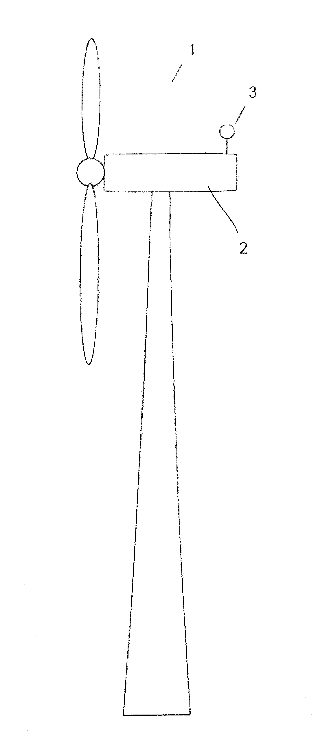
[0016] FIG. 1 shows a schematic view of a wind turbine;
[0017] FIG. 2 shows the structure of a weather mast according to the invention;
[0018] FIG. 3 shows a circuit diagram including a schematic illustration of the heating wires in the weather masts.
DETAILED DESCRIPTION OF THE DRAWINGS
[0019] FIG. 1 shows a schematic view of a wind turbine 1 including a weather mast 3 situated on the roof of the nacelle 2.
[0020] In FIG. 2, there is shown the structure of a weather mast 3 according to the invention. The stand 6 and the lightning protective cage 4 of the weather mast comprise pipings 5 which are interconnected. The lightning protective cage is formed of two circularly bent pipings 5 which are staggered by 90.degree.. However, a placement at an angle of between 60.degree. and 90.degree. is also possible.
[0021] In FIG. 3, there is shown an embodiment of the solution according to the invention. On the nacelle (not shown) of the wind turbine there are arranged two weather masts. One or a plurality of heating wires 7 are installed into the pipings of the stands 6 and the lightning protective cages 4. These heating wires 7 of the individual weather masts 3 are connected in parallel and are connected to a power supply 8. The piping of the weather mast 3 and the heating wires 7 are connected to earth separately. Thus, the lightning protection will not be impaired and the heating wires 7 are protected against lightning stroke as well (Faraday cage).
[0022] In the illustrated embodiment the control of the heating system is carried out by means of the plant control 9 of the wind turbine. From an adjustable environmental condition on (e.g. temperature threshold value) the heating system is energized. Thus, it is made sure that the measurement of the wind speed and of the wind direction will not be impaired by ice build-up on the weather masts 3 which would result in a plant standstill meaning a yield loss. In combination with a reliable ice warning system and an intelligent control system it is possible to further reduce the energy demand for the heating system.
[0023] The heating wires 7 are maintenance-free and can easily be replaced in the event of damage without jeopardizing the operation of the plant.
* * * * *
D00000
D00001
D00002
D00003
XML
uspto.report is an independent third-party trademark research tool that is not affiliated, endorsed, or sponsored by the United States Patent and Trademark Office (USPTO) or any other governmental organization. The information provided by uspto.report is based on publicly available data at the time of writing and is intended for informational purposes only.
While we strive to provide accurate and up-to-date information, we do not guarantee the accuracy, completeness, reliability, or suitability of the information displayed on this site. The use of this site is at your own risk. Any reliance you place on such information is therefore strictly at your own risk.
All official trademark data, including owner information, should be verified by visiting the official USPTO website at www.uspto.gov. This site is not intended to replace professional legal advice and should not be used as a substitute for consulting with a legal professional who is knowledgeable about trademark law.