Carrying Cases Having Adjustable Compartments For Use With Portable Electronic Devices And Related Methods
Thomas; Margaret Rose
U.S. patent application number 13/171225 was filed with the patent office on 2011-12-29 for carrying cases having adjustable compartments for use with portable electronic devices and related methods. This patent application is currently assigned to TARGUS GROUP INTERNATIONAL, INC.. Invention is credited to Margaret Rose Thomas.
| Application Number | 20110315589 13/171225 |
| Document ID | / |
| Family ID | 45351518 |
| Filed Date | 2011-12-29 |


| United States Patent Application | 20110315589 |
| Kind Code | A1 |
| Thomas; Margaret Rose | December 29, 2011 |
CARRYING CASES HAVING ADJUSTABLE COMPARTMENTS FOR USE WITH PORTABLE ELECTRONIC DEVICES AND RELATED METHODS
Abstract
According to various embodiments, a carrying case may be configured with an internal compartment adapted to receive a laptop computer, netbook, tablet computer, touch screen, multimedia projector, mobile telephone, and/or other portable electronic device. The dimensions of a compartment may be adapted for a specific device by moving adjustable cushions from a side spacing orientation to a base spacing orientation. According to one embodiment, a compartment may include adjustable cushions configured to be placed within the compartment in a side spacing orientation or outside the compartment in an external orientation. Additionally, a carrying case may include an instruction icon illustrating methods for using adjustable cushions within a compartment.
| Inventors: | Thomas; Margaret Rose; (Los Angeles, CA) |
| Assignee: | TARGUS GROUP INTERNATIONAL,
INC. Anaheim CA |
| Family ID: | 45351518 |
| Appl. No.: | 13/171225 |
| Filed: | June 28, 2011 |
Related U.S. Patent Documents
| Application Number | Filing Date | Patent Number | ||
|---|---|---|---|---|
| 61359672 | Jun 29, 2010 | |||
| Current U.S. Class: | 206/521 |
| Current CPC Class: | G06F 1/1628 20130101; A45C 3/02 20130101; A45C 2013/025 20130101; A45F 3/04 20130101; A45C 2011/003 20130101; A45C 13/02 20130101 |
| Class at Publication: | 206/521 |
| International Class: | B65D 81/02 20060101 B65D081/02 |
Claims
1. A carrying case for a portable electronic device comprising: an internal compartment comprising: a front panel; a rear panel opposing and spaced apart from the front panel; a first sidewall and a second sidewall opposing one another and joined to the front and rear panels along corresponding side edges of the front and rear panels; a base panel joined to each of the front panel, rear panel, first sidewall, and second sidewall along a base edge of each of the front panel, rear panel, first sidewall, and second sidewall; and a first adjustable cushion attached to the compartment at a first attachment region; a second adjustable cushion attached to the compartment at a second attachment region; and wherein the first and second adjustable cushions are configured to move between a first orientation and a second orientation; and wherein in the first orientation, the first adjustable cushion extends substantially parallel to an interior surface of the first sidewall and the second adjustable cushion extends substantially parallel to an interior surface of the second sidewall.
2. The carrying case of claim 1, wherein the first and second adjustable cushions comprise substantially compliant structures configured to absorb energy from impact so as to protect a portable electronic device.
3. The carrying case of claim 2, wherein the substantially compliant structures comprise a polymeric foam material.
4. The carrying case of claim 1, wherein, the first adjustable cushion comprises a first connector and the compartment comprises a second connector configured to cooperate with the first connector to selectively retain the first cushion in the first orientation; and wherein the second adjustable cushion comprises a third connector and the compartment comprises a fourth connector configured to cooperate with the third connector to selectively retain the second adjustable cushion in the first orientation.
5. The carrying case of claim 1, wherein the first and second adjustable cushions are configured to pivot about the first and second attachment regions, respectively.
6. The carrying case of claim 1, wherein the first attachment region is adjacent the location the first sidewall panel is joined to the base panel; the second attachment region is adjacent the location the second sidewall panel is joined to the base panel; and wherein in the second orientation, the first and second adjustable cushions are adjacent to an interior surface of the base panel and extend substantially parallel thereto.
7. The carrying case of claim 1, wherein the first attachment region is located at an end of the first sidewall opposite the base panel; the second attachment region is located at an end of the second sidewall opposite the base panel; and wherein in the second orientation, at least a portion of the first adjustable cushion and a portion of the second adjustable cushion are exterior to the compartment.
8. The carrying case of claim 1, further comprising an instruction icon including representative illustrations of at least three permutations of the first adjustable cushion and the second adjustable cushion in the first and second orientations.
9. A carrying case for a portable electronic device comprising: an internal compartment comprising: a front panel; a rear panel opposing and spaced apart from the front panel; a first sidewall and a second sidewall opposing one another and joined to the front and rear panels along corresponding side edges of the front and rear panels; a base panel joined to each of the front panel, rear panel, first sidewall, and second sidewall along a base edge of each of the front panel, rear panel, first sidewall, and second sidewall; and a first adjustable cushion configured to move between a first orientation and a second orientation and attached to the compartment at a first attachment region; a second adjustable cushion configured to move between a first orientation and a second orientation and attached to the compartment at a second attachment region; and wherein the first adjustable cushion includes an extension and a notch located on an end opposite the first attachment region and the second adjustable cushion includes a corresponding extension and a notch located on an end opposite the second attachment region; and wherein the extension of each of the first and second adjustable cushions is aligned with the notch of the other adjustable cushion, such that in the second orientation the first and second cushions are positioned adjacent to an interior surface of the base panel and extend substantially parallel thereto.
10. The carrying case of claim 9, wherein in the first orientation, the first adjustable cushion extends substantially parallel to an interior surface of the first sidewall and the second adjustable cushion extends substantially parallel to an interior surface of the second sidewall.
11. The carrying case of claim 9, wherein the first and second adjustable cushions comprise substantially compliant structures configured to absorb energy from impact so as to protect a portable electronic device.
12. The carrying case of claim 11, wherein the substantially compliant structures comprise a polymeric foam material.
13. The carrying case of claim 9, wherein, the first adjustable cushion comprises a first connector and the compartment comprises a second connector configured to cooperate with the first connector to selectively retain the first cushion in the first orientation; and wherein the second adjustable cushion comprises a third connector and the compartment comprises a fourth connector configured to cooperate with the third connector to selectively retain the second adjustable cushion in the first orientation.
14. The carrying case of claim 9, wherein the first and second adjustable cushions are configured to pivot about the first and second attachment regions, respectively.
15. The carrying case of claim 9, further comprising an instruction icon including representative illustrations of at least three permutations of the first adjustable cushion and the second adjustable cushion in the first and second orientations.
16. A carrying case for a portable electronic device comprising: an internal compartment comprising: a front panel; a rear panel opposing and spaced apart from the front panel; a first sidewall and a second sidewall opposing one another and joined to the front and rear panels along corresponding side edges of the front and rear panels; a base panel joined to each of the front panel, rear panel, first sidewall, and second sidewall along a base edge of each of the front panel, rear panel, first sidewall, and second sidewall; and an adjustable cushion comprising: a base portion configured to extend substantially parallel to the base panel; a first side portion configured to move between a first orientation and second orientation, wherein in the first orientation the first side portion extends substantially parallel to an interior surface of the first sidewall; and a second side portion configured to move between a first orientation and second orientation, wherein in the first orientation the second side portion extends substantially parallel to an interior surface of the second sidewall.
17. The carrying case of claim 16, wherein the first side portion and the second side portion are attached to the base portion.
18. The carrying case of claim 17, wherein the first side portion and the second side portion are attached to the base portion via living hinges.
19. The carrying case of claim 16, wherein the first side portion, the second side portion, and the base portion are formed from a unitary piece of material.
20. The carrying case of claim 16, wherein the adjustable cushion comprises a substantially compliant structure configured to absorb energy from impact so as to protect a portable electronic device.
21. The carrying case of claim 20, wherein the substantially compliant structure comprises a polymeric foam material.
22. The carrying case of claim 20, wherein, the first side portion comprises a first connector and the compartment comprises a second connector configured to cooperate with the first connector to selectively retain the first side portion in the first orientation; and wherein the second side portion comprises a third connector and the compartment comprises a fourth connector configured to cooperate with the third connector to selectively retain the second side portion in the first orientation.
23. The carrying case of claim 16, wherein in the second orientation, the first side portion and the second side portion are adjacent to an interior surface of the base portion and extend substantially parallel thereto.
24. The carrying case of claim 20, wherein in the second orientation, one of the first side portion and the second side portion overlap the other of the first side portion and the second side portion.
25. The carrying case of claim 16, further comprising an instruction icon including representative illustrations of at least three permutations of the first side portion and the second side portion in the first and second orientations.
Description
RELATED APPLICATIONS
[0001] The present application claims the benefit under 35 U.S.C. .sctn.119(e) of U.S. Provisional Patent Application No. 61/359,672 filed Jun. 29, 2010, titled "Carrying Cases Having Adjustable Compartments For Use With Portable Computers And Related Methods," which application is incorporated herein by reference in its entirety.
TECHNICAL FIELD
[0002] The present disclosure relates generally to cases for portable electronic devices.
BRIEF DESCRIPTION OF THE DRAWINGS
[0003] Non-limiting and non-exhaustive embodiments of the disclosure are described, including various embodiments of the disclosure with reference to the figures, in which:
[0004] FIG. 1 illustrates a perspective view of an embodiment of a carrying case including a compartment configured to receive a portable electronic device.
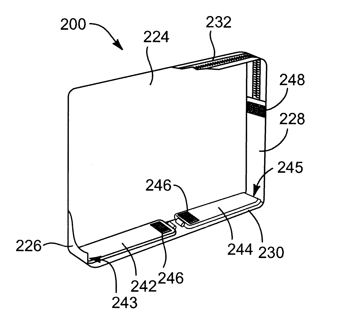
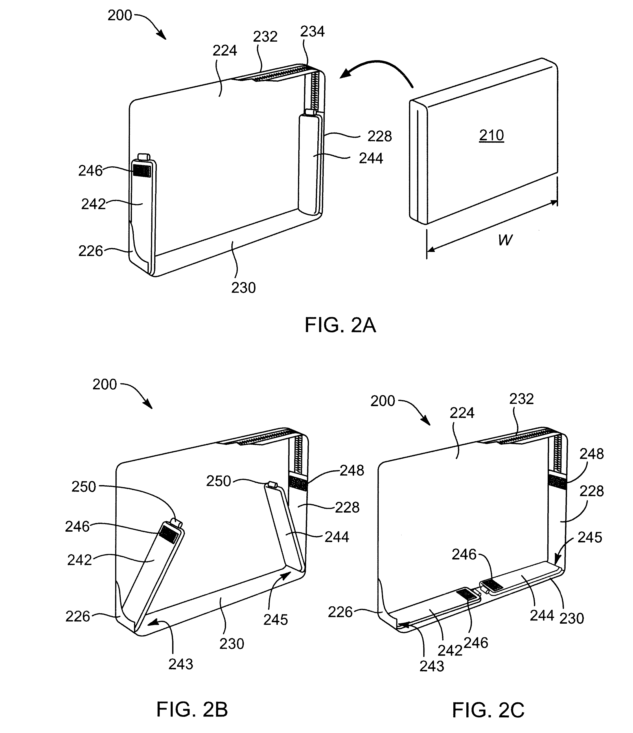
[0005] FIG. 2A illustrates a cutaway view of a compartment formed in a carrying case including adjustable cushions positioned in a side spacing orientation.
[0006] FIG. 2B illustrates a cutaway view of an embodiment of a carrying case including adjustable cushions transitioning away from a side spacing orientation.
[0007] FIG. 2C illustrates a cutaway view of an embodiment of a carrying case including adjustable cushions positioned in a base spacing orientation.
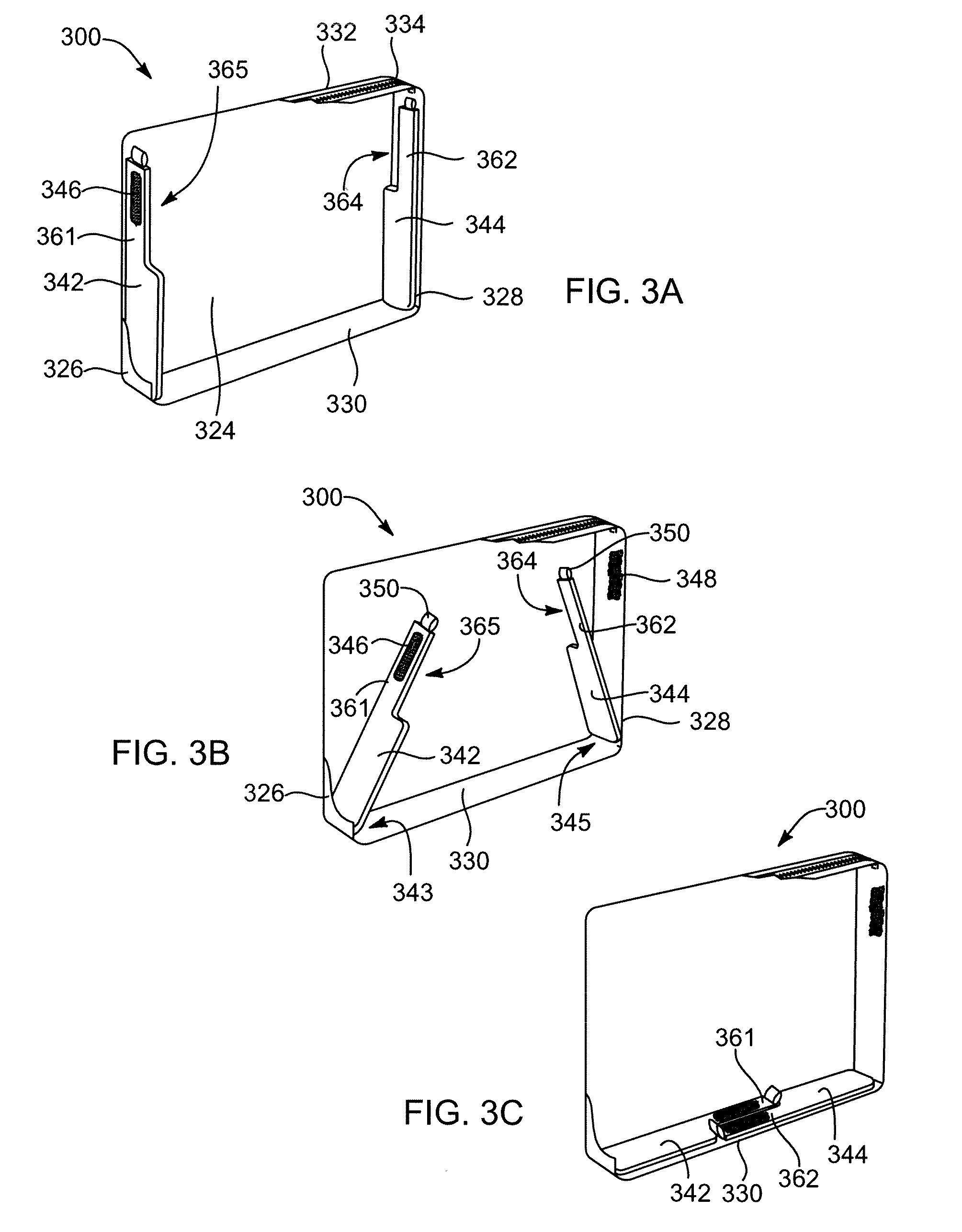
[0008] FIG. 3A illustrates a cutaway view of an embodiment of a compartment including two adjustable notched cushions positioned in a side spacing orientation.
[0009] FIG. 3B illustrates a cutaway view of an embodiment of a compartment including adjustable notched cushions transitioning away from a side spacing orientation.
[0010] FIG. 3C illustrates a cutaway view of an embodiment of a compartment including adjustable notched cushions positioned in a base spacing orientation.
[0011] FIG. 4 is a perspective view of an embodiment of a carrying case including a compartment configured to receive a portable electronic device.
[0012] FIG. 5A is a cross-sectional view of a compartment including adjustable cushions in a side spacing orientation.
[0013] FIG. 5B is a cross-sectional view of a compartment including adjustable overlapping cushions in a base spacing orientation.
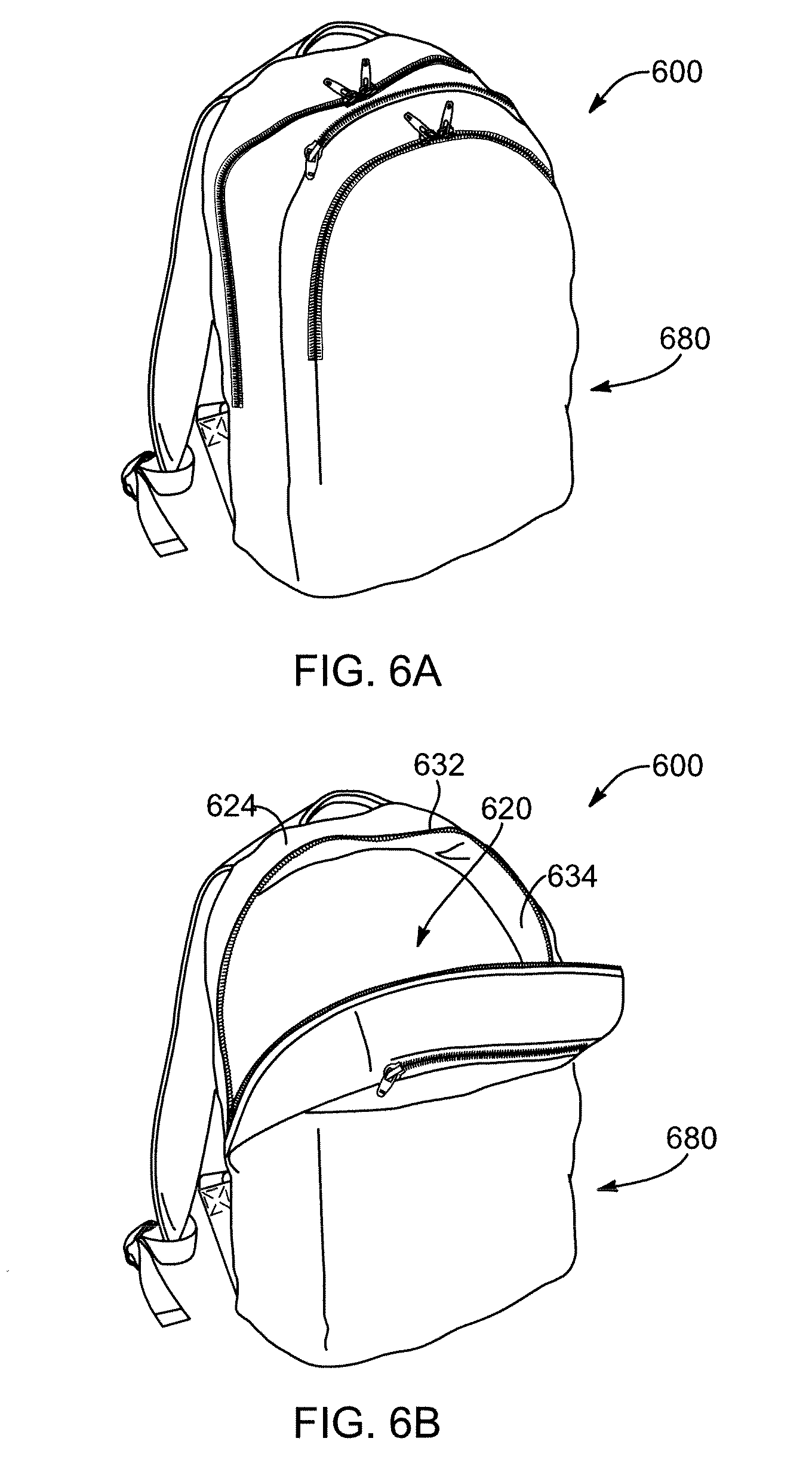
[0014] FIG. 6A illustrates an embodiment of a carrying case including a compartment configured to receive a portable electronic device in a closed configuration.
[0015] FIG. 6B illustrates an embodiment of a carrying case including a compartment configured to receive a portable electronic device in an open configuration.
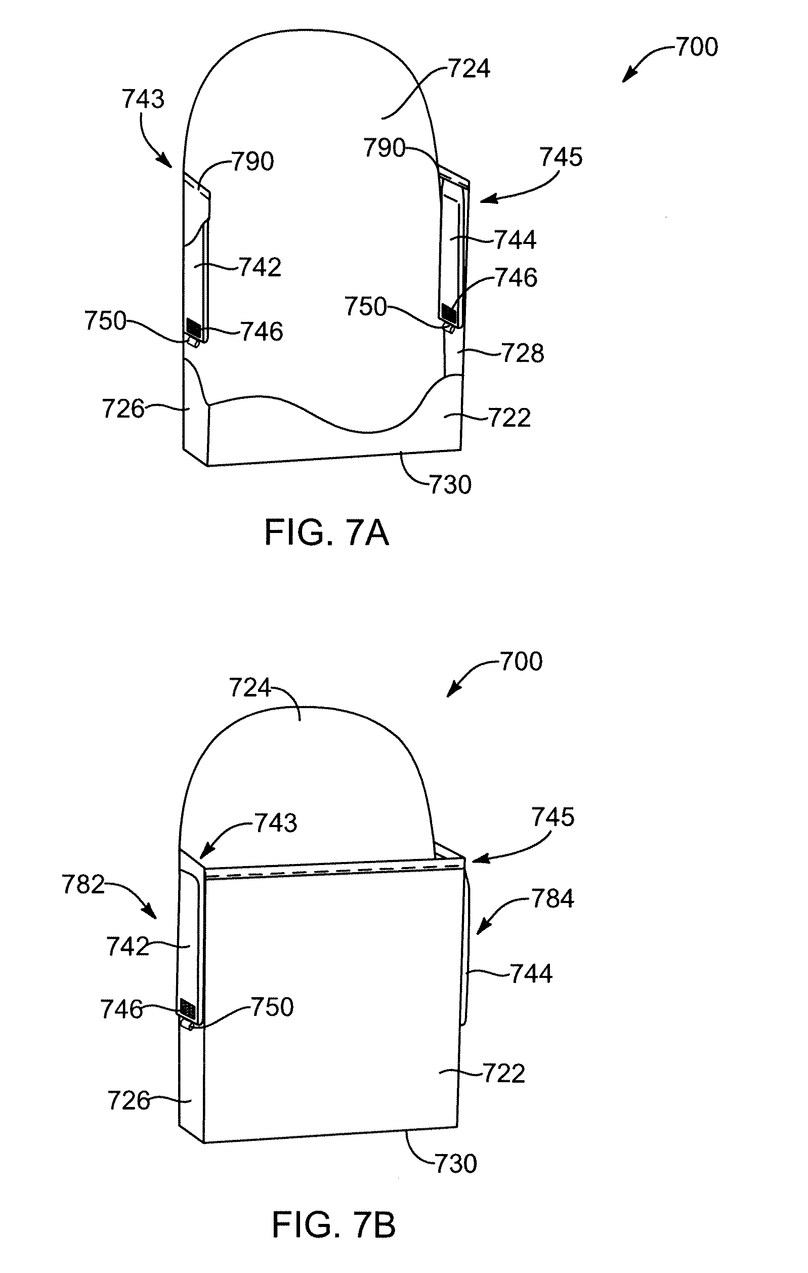
[0016] FIG. 7A illustrates a cutaway view of an embodiment of a compartment including adjustable cushions in a side spacing orientation.
[0017] FIG. 7B illustrates a cutaway view of an embodiment of a compartment including adjustable cushions in an external orientation.
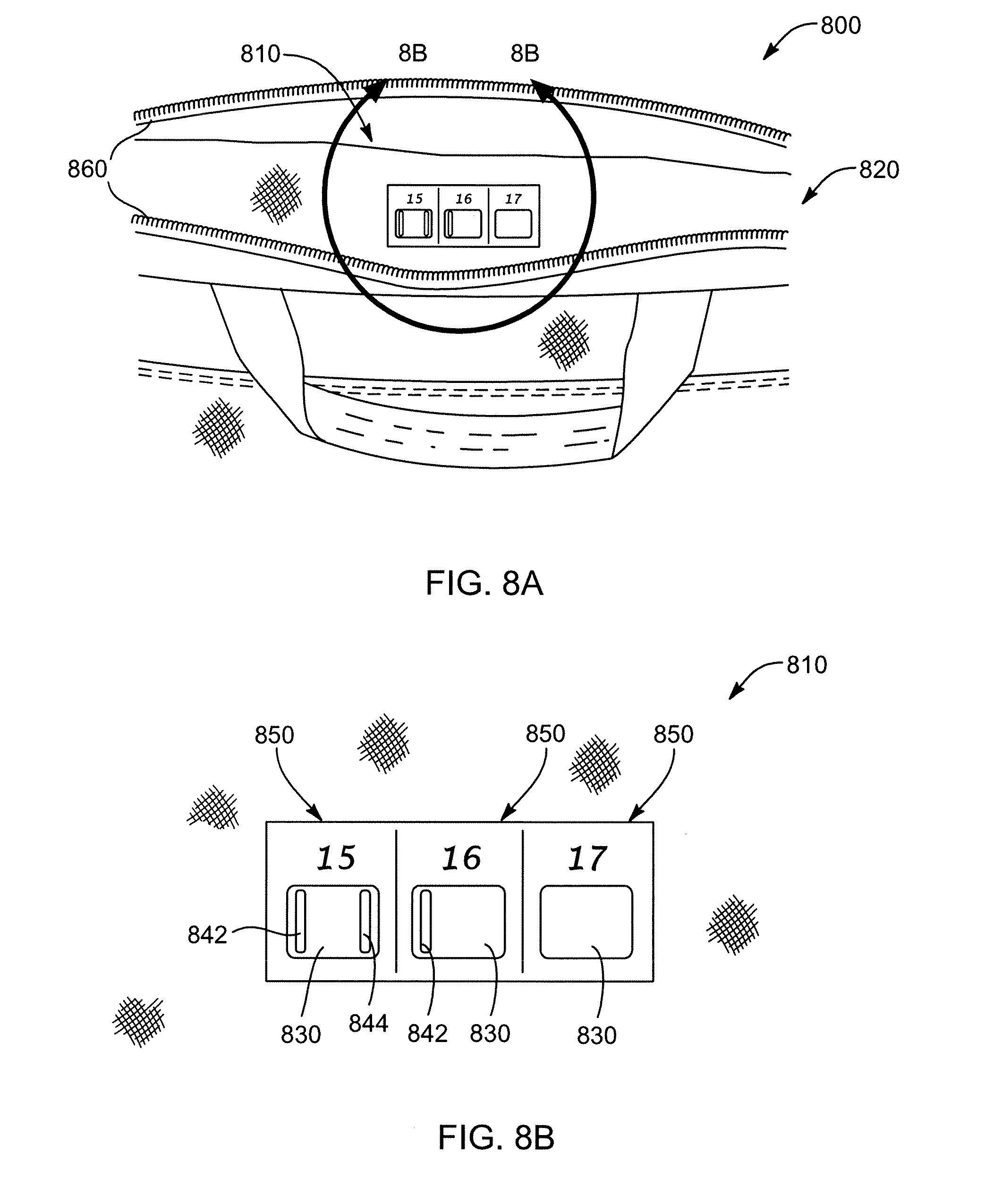
[0018] FIG. 8A is a perspective view of a portion of an embodiment of a carrying case including an instruction icon.
[0019] FIG. 8B illustrates an enlarged view of the instruction icon in FIG. 15A.
[0020] In the following description, numerous specific details are provided for a thorough understanding of the various embodiments disclosed herein. The systems and methods disclosed herein can be practiced without one or more of the specific details, or with other methods, components, materials, etc. In addition, in some cases, well-known structures, materials, or operations may not be shown or described in detail in order to avoid obscuring aspects of the disclosure. Furthermore, the described features, structures, or characteristics may be combined in any suitable manner in one or more alternative embodiments.
DETAILED DESCRIPTION
[0021] The present disclosure provides various embodiments of and methods for using carrying cases configured with adjustable compartments for securing any of a variety of portable electronic devices. A carrying case may be configured with an internal compartment adapted to receive a laptop computer, netbook, tablet computer, touch screens, multimedia projectors, mobile telephones, and/or other portable electronic devices.
[0022] Portable electronic devices are available in a variety of sizes. For example, the diagonal measurements of many laptop computers ranges from about thirteen inches to about seventeen inches. Of course, laptop computers and other portable electronic devices are also available in larger or smaller sizes. Accordingly, it may be desirable for a compartment of a carrying case for portable electronic devices to be adjustable so as to securely accommodate various models, sizes, and/or types of portable electronic devices within a given size range. For example, a carry case may be configured to specifically accommodate laptop computers with diagonal screen measurement ranging from about fifteen inches to about 17 inches.
[0023] According to various embodiments, the cavity or compartment of a carrying case may be an integral component of the carrying case. According to alternative embodiments, the compartment may be removable and/or detachable from other portions of the carrying case. Additionally, a carrying case may be interchangeably paired with multiple sizes and/or shapes of compartments. Accordingly, a single carrying case may be adapted to accommodate portable electronic devices of varying size ranges by inserting or attaching an appropriate compartment.
[0024] According to various embodiments, a carrying case may include one or more straps or handles. Additionally, a carrying case may include one or more wheels and/or telescoping handles to facilitate the transportation of a portable electronic device. According to various embodiments, a carrying case may include a closure mechanism for selectively opening and closing a compartment configured to receive a portable electronic device. For example, a carrying case may include one or more flaps, buttons, zippers, latches, snaps, and/or locks allowing a user to selectively insert and remove a portable electronic device from a compartment.
[0025] According to various embodiments, a compartment within a carrying case may be configured to accommodate portable electronic devices of varying sizes through the use of one or more cushions, pads, or strips. The dimensions of a compartment may be adjusted through the use of cushions configured to pivot from a side spacing orientation to a base spacing orientation. The adjustable cushions may be positioned in a side spacing orientation in order to reduce the internal width of the compartment, or pivoted into a base spacing orientation to expand the internal width and/or reduce the internal height of the compartment. According to various embodiments, the adjustable cushions may be permanently secured at a pivot point, detachably secured at a pivot point, or unsecured at the pivot point.
[0026] According to one embodiment, a compartment of a carrying case may be defined by a front panel, a rear panel, a left sidewall panel, a right sidewall panel, a base panel, and an upper panel. According to various embodiments, the upper panel, and/or potentially a portion of one or more other panels, may include a closure mechanism for selectively opening the compartment. In a side spacing orientation, a left adjustable cushion may extend along the left sidewall panel and a right adjustable cushion may extend along the right sidewall panel. Transitioning the adjustable cushions from a side spacing orientation to a base spacing orientation may entail pivoting the adjustable cushions until they extend along the base panel of the compartment. According to various embodiments, the combined length of the left and right cushions may be equal to or less than the length of the base panel. Alternatively, the left and right cushions may overlap one another in a base spacing orientation.
[0027] According to one embodiment, a compartment may include adjustable cushions that can be placed within the compartment in a side spacing orientation or outside the compartment in an external orientation. Additionally, a carrying case and/or compartment may include an instruction icon illustrating methods for using adjustable cushions within a compartment. For example, an instruction icon may include graphical depictions of various possible orientations for left and right adjustable cushions within a compartment. According to one specific example, an instruction icon may depict several possible orientations for adjustable cushions in order for a compartment to accommodate a fifteen-inch laptop, a sixteen-inch laptop, or a seventeen-inch laptop.
[0028] Throughout the disclosure, numerous examples are provided with reference to laptop computers; however, the various embodiments of carrying cases described herein may be used for or adapted for carrying any of a wide variety of portable electronic devices and/or other sensitive or delicate equipment. For clarity, the illustrated embodiments show only a single compartment configured to receive a portable electronic device. However, according to various embodiments, a carrying case may include multiple compartments, each configured to receive a portable electronic device. Additionally, a carrying case may include any number of additional pockets, compartments, zippers, mesh areas, elastics, rings, hooks, latches, and/or similar items configured to accommodate additional items, such as keys, pens, paper, folders, power cords, batteries, mobile phones, clothing, and/or the like.
[0029] Reference throughout this specification to "one embodiment" or "an embodiment" means that a particular feature, structure, or characteristic described in connection with the embodiment is included in at least one embodiment. Thus, the appearances of the phrases "in one embodiment" or "in an embodiment" in various places throughout this specification are not necessarily all referring to the same embodiment. In particular, an "embodiment" may be a system, an article of manufacture (such as a computer-readable storage medium), a method, and/or a product of a process.
[0030] Throughout this specification the term "joined" may be used to describe two or more components that are attached to one another, or the term may be used to describe two portions of an integral component. Accordingly, the term "joined" may be used to describe two panels manufactured as disparate components that are sewn, glued, fused, or otherwise attached to one another; additionally, the term "joined" may be used to describe two panels that are manufactured as a single integral component and are separate only for ease of description. For example, a compartment may be formed wherein the bottom panel, the front panel, and the rear panel are manufactured as a single integral component. However, throughout the description and claims, such a compartment may be described as comprising a base panel joined to opposing front and rear panels along their respective base edges.
[0031] In some cases, well-known features, structures or operations are not shown or described in detail. Furthermore, the described features, structures, or operations may be combined in any suitable manner in one or more embodiments. It will also be readily understood that the components of the embodiments as generally described and illustrated in the figures herein could be arranged and designed in a wide variety of different configurations.
[0032] The embodiments of the disclosure are best understood by reference to the drawings, wherein like parts are designated by like numerals throughout. It will be readily understood that the components of the disclosed embodiments, as generally described and illustrated in the figures herein, could be arranged and designed in a wide variety of different configurations. Thus, the following detailed description of the embodiments of the systems and methods of the disclosure is not intended to limit the scope of the disclosure, as claimed, but is merely representative of possible embodiments of the disclosure. In other instances, well-known structures, materials, or operations are not shown or described in detail to avoid obscuring aspects of this disclosure. In addition, the steps of a method do not necessarily need to be executed in any specific order, or even sequentially, nor need the steps be executed only once, unless specifically stated.
[0033] FIG. 1 illustrates an embodiment of a carrying case 100 including an adjustable compartment configured to receive a portable electronic device. Carrying case 100 may be of any suitable variety, such as a shoulder bag, backpack, briefcase, or the like. In the illustrated embodiment, carrying case 100 is of a shoulder bag variety and includes a shoulder strap 105. According to various embodiments, one or more additional or alternative handles or straps may be employed in conjunction with carrying case 100.
[0034] Carrying case 100 may be adapted to accommodate a laptop computer, a netbook, tablet computer, a touch screen, a multimedia projector, a mobile telephone, and/or other portable electronic device. According to various embodiments, an internal compartment may be defined by a front panel 122, a rear panel 124, a left sidewall panel 126, a right sidewall panel (not visible in FIG. 1), a base panel 130, and an upper panel 132. As illustrated, upper panel 132 may include a closure mechanism such as zipper 134 and/or flap 107. Throughout the description front panel 122, rear panel 124, left sidewall panel 126, right sidewall panel (not visible), base panel 130, and upper panel 132 are discussed a separate components forming a compartment; however, according to various embodiments, two or more panels may actually be portions of an integral component.
[0035] According to various embodiments and as illustrated, an internal compartment may define a substantially right parallelepiped shape. However, according to various embodiments, the exact shape and/or dimensions of an internal compartment may be adapted to accommodate any of a wide variety of portable electronic devices. For example, the internal compartment may include a protrusion or intrusion to accommodate a corresponding feature on a portable electronic device.
[0036] According to various embodiments, upper panel 132 may be a separate panel or may be integrally formed as a part of the sidewall panels and/or front and rear panels. Upper panel 132 may include one or more closure mechanisms for selectively opening the internal compartment, such as zipper 134, a flap 107, a latch 106, a button, a zipper, a snap, and/or a lock. Additionally, carrying case 100 may include any number of additional pockets, compartments, zippers, mesh areas, elastics, rings, hooks, latches, wheels, straps, handles and/or other features.
[0037] FIG. 2A illustrates a cutaway view of a compartment 200 formed in a carrying case including adjustable cushions 242 and 244 positioned in a side spacing orientation. As illustrated, a left adjustable cushion 242 and a right adjustable cushion 244 may be positioned within compartment 200 defined by base panel 230, left sidewall panel 226, right sidewall panel 228, rear panel 224, upper panel 232, and a front panel (not shown in FIG. 2).
[0038] According to various embodiments, compartment 200 may be configured with an appropriate dimension and size to accommodate any of a wide variety of portable electronic devices. For example, compartment 200 may be adapted to accommodate a laptop 210 (or other portable electronic device) having a width W. According to various embodiments, left adjustable cushion 242 and right adjustable cushion 244 may be used to adjust the interior dimensions of compartment 200. In particular, adjustable cushions 242 and 244 may be oriented in a variety of permutations in order to accommodate portable electronic devices of varying widths W and/or heights.
[0039] According to various embodiments, adjustable cushions 242 and 244 may comprise a compliant structure configured to absorb energy from an impact so as to protect a portable electronic device stored within compartment 200. Additionally, adjustable cushions 242 and 244 may be formed of a resilient material in order to return to their original shape after being compressed. According to various embodiments, adjustable cushions 242 and 244 may comprise any suitable compliant and/or resilient structure, such as, for example, a polymeric foam material.
[0040] According to some embodiments, compartment 200 may include one or more additional compliant and/or resilient structures adapted to reduce the internal dimensions of compartment 200 and/or protect a secured portable electronic device by absorbing energy during an impact.
[0041] Adjustable cushions 242 and 244 may be configured to transition from a side spacing orientation to a base spacing orientation. In a side spacing orientation, the left 242 and right 244 adjustable cushions may extend substantially parallel to the interior surfaces of the left 226 and right 228 sidewall panels, respectively. According to various embodiments, adjustable cushions 242 and 244 may be configured to extend along only a portion of sidewall panels 226 and 228. For instance, an edge of each adjustable cushion 242 and 244 may terminate at or near the endpoints of zipper 234.
[0042] FIG. 2B illustrates a cutaway view of compartment 200 with adjustable cushions 242 and 244 transitioning from a side spacing orientation (see FIG. 2A) to a base spacing orientation (see FIG. 2C). According to various embodiments, adjustable cushions 242 and 244 may be fixedly attached to an internal wall of compartment 200 at an attachment region 243 and 245, respectively. Adjustable cushions 242 and 244 may be configured to pivot about attachment regions 243 and 245 from the side spacing orientation (FIG. 2A) to the base spacing orientation (FIG. 2C). According to alternative embodiments, an adjustable cushion may be selectively detachable, permanently attached, and/or integral with sidewall panel 226 and 228 and/or base panel 230.
[0043] Additionally, each adjustable cushion 242 and 244 may include a connector 246 configured to function in cooperation with a connector 248 on each of the left 226 and right 228 sidewall panels. For example, connector 246 locate on adjustable cushion 244 may cooperate with connector 248 on a right sidewall panel 228 in order to selectively retain adjustable cushion 244 in the side spacing orientation. Any suitable connection system may be used, such as hook and loop fasteners (e.g., Velcro.RTM.), snaps, magnets, etc. In certain embodiments, each adjustable cushion 242 and 244 may include a tab 250 that can be readily gripped by a user when disengaging connectors 246 and 248 from each other.
[0044] As shown in FIG. 2C, when adjustable cushions 242 and 244 are in the base spacing orientation, they may be positioned adjacent and parallel to an interior surface of base panel 230. According to various embodiments, adjustable cushions 242 and 244 do not overlap one another or contact one another when in the base spacing orientation. For example, in the illustrated embodiment each adjustable cushion 242 and 244 defines a length slightly less than one half the width defined by base panel 230.
[0045] In the illustrated embodiment, adjustable cushions 242 and 244 are fixedly attached to compartment 200 at a left attachment region 243 and at a right attachment region 245, respectively. Moreover in the illustrated embodiment, each attachment region 243 and 245 is at an intersection of base panel 230 and the left 226 and right 228 sidewall panels, respectively. Any suitable mechanism may be employed to fixedly secure adjustable cushions 242 and 244 to compartment 200. For example, in various embodiments, adjustable cushions 242 and 244 may be stitched to compartment 200.
[0046] Compartment 200 may be configured for use with a portable computer 210 having any width W. Compartment 200 may be prepared to receive portable computer 210 by placing both adjustable cushions 242 and 244 in the side spacing orientation, as shown in FIG. 2A Compartment 200 may be prepared to receive a wider portable computer by placing both adjustable cushions 242 and 244 in a base spacing orientation, as shown in FIG. 2C. Compartment 200 may also be prepared to receive a portable computer of an intermediate width by placing one of adjustable cushions 242 and 244 in the side spacing orientation and the other of adjustable cushions 242 and 244 in the base spacing orientation.
[0047] Adjustable cushions 242 and 244 may be dimensioned in any suitable manner to provide a relatively close fit or, in some instances, a snug fit along the side edges of portable computers having different sizes. In some embodiments, each adjustable cushion 242 and 244 is substantially the same size and shape. For example, in some embodiments, each adjustable cushion 242 and 244 defines the same thickness such that adjustable cushions 242 and 244 cooperate to define a substantially planar surface on which a base edge of portable computer 210 can rest when adjustable cushions 242 and 244 are in the base spacing orientation.
[0048] In certain embodiments, one or more of the front panel (122 in FIG. 1), rear panel 224, left sidewall panel 226, right sidewall panel 228, base panel 230, and upper panel 232 may be structurally reinforced (e.g., stiff) so as to maintain the shape and configuration of compartment 200 independent of the orientation of adjustable cushions 242 and 244. Alternatively, compartment 200 may be configured to be collapsible when adjustable cushions 242 and 244 are in one or both of the side spacing position and the base spacing position.
[0049] According to various alternative embodiments, adjustable cushions 242 and 244 may contact each other when in the base spacing orientation. Additionally, one of adjustable cushions 242 and 244 may overlap the other when in the base spacing orientation. In some embodiments, adjustable cushions 242 and 244 may be removable from compartment 200. In some embodiments, a set of connectors 246 may be provided on opposite sides of adjustable cushions 242 and 244, and base panel 230 may include a corresponding set of connectors, such that adjustable cushions 242 and 244 may be selectively secured in the base spacing orientation. In other or further embodiments, connectors 248 may be omitted from sidewall panels 226 and 228, and corresponding connectors 246 may likewise be omitted from cushions 242 and 244. In other or further embodiments, compartment 200 may include only a single adjustable cushion 242 or 244.
[0050] FIGS. 3A-3C illustrate alternative embodiments of a compartment 300 of a carrying case. Many features of the embodiments illustrated in FIGS. 3A-3C are similar or identical to those illustrated and described in conjunction with FIGS. 2A-2C. Accordingly, the relevant descriptions of similar or identical features of FIGS. 2A-2C apply equally to the features of compartment 300. Any suitable combination of the features and variations described with respect to compartment 200 may be applicable to and employed with compartment 300, and vice versa. This pattern of disclosure applies equally to further embodiments depicted in subsequent figures and described hereafter.
[0051] According to the illustrated embodiment, compartment 300 may be defined by a base panel 330, a left sidewall panel 326, a right sidewall panel 328, a rear panel 324, and a front panel (not shown in FIG. 3). Compartment 300 may include a left adjustable cushion 342 configured with an extension 361 and a notch 365 and a right adjustable cushion 344 configured with an extension 362 and a notch 364. According to various embodiments, extension 361 of left adjustable cushion 342 corresponds to notch 364 of right adjustable cushion 344. Likewise, extension 362 of right adjustable cushion 344 corresponds to notch 365 of left adjustable cushion 342.
[0052] According to various embodiments, connectors 346 may be located on the extension portions 361 and 362 of left 342 and right 344 adjustable cushions. As illustrated in the cut-away view provided in FIG. 3A, connectors 346 may be configured to cooperate in conjunction with connectors 348 (see FIG. 3B) located on internal sidewall panels 326 and 328 in order to selectively secure left 342 and right 344 adjustable cushions to sidewall panels 326 and 328 in the side spacing orientation. According to various embodiments, extensions 361 and 362 may be sufficiently short that they do not come into contact with upper panel 332 and/or zipper 334.
[0053] As illustrated in FIG. 3B, adjustable cushions 342 and 344 may be fixedly attached to an internal wall of compartment 300 at attachment regions 343 and 345, respectively. Accordingly, adjustable cushions 342 and 344 may pivotally transition from a side spacing orientation (see FIG. 3A) to a base spacing orientation (see FIG. 3C). According to alternative embodiments, adjustable cushion 342 and 344 may be selectively detachable, permanently attached, and/or integral with sidewall panel 326 and 328 and/or base panel 330. In some embodiments, adjustable cushions 342 and 344 may include tabs 350 extending from extensions 361 and 362 of adjustable cushions 342 and 344, respectively. Tabs 350 may assist a user in transitioning adjustable cushions 342 and 344 from the base spacing orientation to the side spacing orientation, and vice versa.
[0054] As illustrated in FIG. 3B and 3C, when adjustable cushions 342 and 344 are transitioning to the base spacing orientation, extension 361 may be received within notch 364 and extension 362 may be received within notch 365. According to one embodiment, adjustable cushions 342 and 344 may contact each other so as to define a solid (e.g., continuous) base cushion that covers or substantially covers base panel 330.
[0055] FIG. 4 illustrates an embodiment of a carrying case 400 resembling that of a brief case. According to various embodiments, carrying case 400 may include a handle 407 and/or a shoulder strap 405. Carrying case 400 may include any number of additional pockets, compartments, zippers, mesh areas, elastics, rings, hooks, latches, and/or similar items configured to accommodate additional items such as keys, pens, paper, folders, power cords, batteries, mobile phones, clothing, and/or the like. Additionally, carrying case 400 may include a compartment including adjustable cushions, similar to those described in conjunction with FIGS. 1-3C and/or FIGS. 5A-5B.
[0056] FIGS. 5A and 5B illustrate an embodiment of a compartment 500 in which a left adjustable cushion 542, a right adjustable cushion 544, and a base cushion 571 are formed from a unitary piece of material 570. Unitary piece of material 570 may comprise a single piece of polymeric foam or multiple sections of polymeric foam joined together.
[0057] In some embodiments, base cushion 571 may be connected to left 542 and right 544 adjustable cushions by living hinges 572. As illustrated in FIG. 5B, when adjustable cushions 542 and 544 are in the base spacing orientation, right adjustable cushion 544 may be configured to overlap left adjustable cushion 542. Alternatively, left adjustable cushion 542 may be configured to overlap right adjustable cushion 544. According to one embodiment, adjustable cushions 542 and 544 may be shorter so that they do not overlap one another in the base spacing orientation. Additionally, adjustable cushions 542 and 544 may be configured to fold inward at a fold point between living hinges 572 and tabs 550. According to such an embodiment, adjustable cushions 542 and 544 may be configured to fold and thereby not contact one another when in the base spacing orientation.
[0058] FIGS. 6A and 6B illustrate an embodiment of a carrying case 600 resembling a backpack including an outer cover 680. According to various embodiments, carrying case 600 may include a compartment 620 configured to receive a portable electronic device, such as a laptop or a tablet device. As illustrated in FIG. 6B, outer cover 680, sidewall panels 634, and a top panel 624 may define a compartment 620. According to some embodiments, internal panels independent from outer cover 680 may define compartment 620. Additionally, carrying case 600 may include a zipper 632 or other closure mechanism allowing a laptop or other portable electronic device to be selectively received and removed.
[0059] FIGS. 7A and 7B illustrate a compartment 700 configured to receive a portable electronic device. According to various embodiments, compartment 700 may be configured for use in a backpack style carrying case, such as the exemplary backpack illustrated in FIGS. 6A and 6B. According to some embodiments, one or more of a front panel 722, a rear panel 724, a left sidewall panel 726, a right sidewall panel 728, a base panel 730, and an upper panel (not shown) that define compartment 700 may be integral with an outer cover of a carrying case. However, in the illustrated embodiment, at least the left sidewall panel 726 and the right sidewall panel 728 are separate from an outer cover of a carrying case, such that additional external compartments 782 and 784 (FIG. 7B) are provided between sidewall panels 726 and 728 and an outer cover.
[0060] Compartment 700 may include a left adjustable cushion 742 and a right adjustable cushion 744 attached to compartment 700 at connection regions 743 and 745, respectively. Connection regions 743 and 745 may be positioned at the upper ends of the left sidewall panel 726 and right sidewall panel 728, respectively. Each connection region 743 and 745 may include stitching 790 by which adjustable cushions 742 and 744 are fixedly attached to sidewall panels 726 and 728, respectively.
[0061] Adjustable cushions 742 and 744 may be pivoted or rotated about connection regions 743 and 745 between a side spacing orientation (FIG. 7A) and an external orientation (FIG. 7B). Tabs 750 may assist a user in transitioning adjustable cushions 742 and 744 from the base spacing orientation to the side spacing orientation, and vice versa.
[0062] When in the external orientation, adjustable cushions 742 and 744 may be inserted into external compartments 782 and 784, respectively. Alternatively, in an embodiment not including external compartments 782 and 784, adjustable cushions 742 and 744 may extend parallel and adjacent to exterior sidewall panels 726 and 728, respectively. According to various embodiments, adjustable cushions 742 and 744 may include multiple connectors 746, so as to be selectively or temporarily fixed in each of the side spacing and external orientations. Sidewall panels 726 and 728 may include one or more appropriately positioned corresponding connectors (not shown in FIGS. 7A and 7B) to interact with connectors 746.
[0063] FIG. 8A provides a perspective view of an embodiment of a portion of a carrying case 800 including an instruction icon 810 on or near a compartment 820. According to various embodiments, an icon 810 may be included in any of the carrying cases and/or compartments previously described in conjunction with FIGS. 1-7B.
[0064] According to one embodiment, instruction icon 810 may be included within a compartment 820 of carrying case 800, and may be hidden from view when compartment 820 is closed. Compartment 820 may be closed using zipper 860 or through the use of one or more alternative closure mechanisms.
[0065] Instruction icon 810 may depict compartment 820 in various operational configurations. For example, in the illustrated embodiment, instruction icon 810 depicts three different operational configurations. FIG. 8B illustrates an enlarged view of instruction icon 810. As illustrated, each configuration depiction may include a compartment representation 830, representation of possible positioning of one or more adjustable cushions 842 and 844, and a size indicator 850.
[0066] For example, in the left configuration depiction, a left adjustable cushion representation 842 and a right adjustable cushion representation 844 are shown. In the center configuration depiction, only a left adjustable cushion representation 842 is shown. In the right configuration depiction, no adjustable cushion representations are shown. According to one embodiment, the presence of an adjustable cushion representation in a configuration depiction may indicate that an adjustable cushion can be placed in the side spacing orientation in order to achieve the depicted configuration. In the illustrated embodiment, size indicators 550 include the numerals 15, 16, and 17, which signify that the depicted configurations may be used with laptop computers having diagonal measurements of about 15 inches, about 16 inches, and about 17 inches, respectively.
[0067] According to various alternative embodiments, size indicators 550 may be modified to suit the type of carrying case utilized. For example, size indicators 550 may be configured to indicate possible configurations for compartments configured to receive laptops having any range of dimensions, netbooks of varying sizes, tablet computers, touch screen devices, portable music players, cellular phones, calculators, peripheral devices, and/or other portable electronic devices. Accordingly, size indicators may include numerical indications (e.g., inches or millimeters), graphical indications (e.g., illustrations of various devices), or a combination thereof. For example, an icon may include an illustration of a generic or brand-specific laptop computer, cellular phone, tablet device, and/or other portable electronic device.
[0068] The above description provides numerous specific details for a thorough understanding of the embodiments described herein. However, those of skill in the art will recognize that one or more of the specific details may be omitted, modified, and/or replaced by a similar process, system, or component. In many instances the order of steps and/or actions of the methods of use described herein may be interchanged with one another.
* * * * *
D00000
D00001
D00002
D00003
D00004
D00005
D00006
D00007
XML
uspto.report is an independent third-party trademark research tool that is not affiliated, endorsed, or sponsored by the United States Patent and Trademark Office (USPTO) or any other governmental organization. The information provided by uspto.report is based on publicly available data at the time of writing and is intended for informational purposes only.
While we strive to provide accurate and up-to-date information, we do not guarantee the accuracy, completeness, reliability, or suitability of the information displayed on this site. The use of this site is at your own risk. Any reliance you place on such information is therefore strictly at your own risk.
All official trademark data, including owner information, should be verified by visiting the official USPTO website at www.uspto.gov. This site is not intended to replace professional legal advice and should not be used as a substitute for consulting with a legal professional who is knowledgeable about trademark law.