Modular Chain Newel With Standard Bearing
Ye; Ke ; et al.
U.S. patent application number 13/255736 was filed with the patent office on 2011-12-29 for modular chain newel with standard bearing. This patent application is currently assigned to OTIS ELEVATOR COMPANY. Invention is credited to Yanying Anne Chen, Qingdong Jiang, Shouhong Wang, Coliu Wu, Ke Ye.
| Application Number | 20110315508 13/255736 |
| Document ID | / |
| Family ID | 42727843 |
| Filed Date | 2011-12-29 |
| United States Patent Application | 20110315508 |
| Kind Code | A1 |
| Ye; Ke ; et al. | December 29, 2011 |
MODULAR CHAIN NEWEL WITH STANDARD BEARING
Abstract
A roller bearing and newel guide assembly (30) for a newel (24) in an escalator (10) has a newel guide (32), a roller chain (34), and a spring (40) connected between the roller chain (34) and the newel guide (32) to provide tension to the roller chain (34). The roller chain (34) comprises a series of interlinked chain units (36). Each chain unit (36) includes a frame (78), at least one roller bearing (72), and a pin (76) for connecting the roller bearing (72) to the frame (78). Each chain unit (36) has a female connector (62) and a male connector (64), which allow each chain unit (36) to connect to an adjacent chain unit (36) to form the roller chain (34).
| Inventors: | Ye; Ke; (Guangzhou, CN) ; Chen; Yanying Anne; (Guangzhou, CN) ; Wu; Coliu; (Guangzhou, CN) ; Wang; Shouhong; (Guangzhou, CN) ; Jiang; Qingdong; (Guangzhou, CN) |
| Assignee: | OTIS ELEVATOR COMPANY Farmington CT |
| Family ID: | 42727843 |
| Appl. No.: | 13/255736 |
| Filed: | March 10, 2009 |
| PCT Filed: | March 10, 2009 |
| PCT NO: | PCT/IB2009/000470 |
| 371 Date: | September 9, 2011 |
| Current U.S. Class: | 198/335 ; 198/850; 29/402.08; 29/525.01 |
| Current CPC Class: | B66B 23/22 20130101; B66B 23/145 20130101; Y10T 29/4973 20150115; B65G 15/60 20130101; B66B 23/147 20130101; B66B 23/24 20130101; Y10T 29/49947 20150115 |
| Class at Publication: | 198/335 ; 198/850; 29/525.01; 29/402.08 |
| International Class: | B66B 23/24 20060101 B66B023/24; B23P 11/00 20060101 B23P011/00; B23P 6/00 20060101 B23P006/00; B66B 23/04 20060101 B66B023/04 |
Claims
1. A handrail assembly for a newel of a passenger conveyor, the assembly comprising: a handrail belt that travels around the newel; a newel guide; a roller chain having a first end and a second end connected to the newel guide, the roller chain comprising a series of interlinked chain units that are each separately removable from the roller chain; and a spring connected between the first end of the roller chain and the newel guide to provide tension to the roller chain in order to maintain contact between the surface area of the roller and the handrail belt.
2. The assembly of claim 1, wherein the second end of the roller chain is connected to the newel guide by a fastener.
3. The assembly of claim 1, each chain unit is connected to an adjacent chain unit in the roller chain, and each chain unit comprises a frame and at least one roller that contacts the handrail belt.
4. The assembly of claim 3, wherein the frame of each chain unit has a male connector and a female connector, and wherein the male connector of one chain unit is engaged with the female connector of an adjacent unit.
5. The assembly of claim 4, wherein the male connector is a hook, and the female connector is a loop.
6. A chain for use in a newel of a passenger conveyor, the chain comprising: a plurality of chain units, each chain unit having a male connector at one end and a female connector at an opposite end, the chain units being detachably linked together in series by engagement of the female connector of one chain unit with the male connector of an adjacent chain unit.
7. The chain of claim 6, wherein each chain unit comprises a frame having a first end and a second end, and at least one roller bearing supported by the frame, and wherein the male connector is adjacent a first end of the frame and the female connector is adjacent a second end of the frame.
8. The chain of claim 7, wherein the male connector is a hook formed in a base portion of the frame and the female connector is a loop pivotally connected to the frame.
9. The assembly of claim 6, and further comprising: a spring connected to an end of the plurality of chain units.
10. A chain unit for use in the newel of a passenger conveyor, the chain unit comprising: a frame comprising a base having a hook adjacent a first end of the base, a loop pivotally coupled to a second end of the base, a first side panel extending upward from the base, and a second side panel extending upward from the base; and at least one roller bearing supported between the first side panel and the second side panel.
11. The chain unit of claim 10, and further comprising: a pin inserted through the first side panel, the inner race of the roller bearing, and the second side panel to support the roller bearing within the frame.
12. The chain unit of claim 11, and further comprising: a bushing inserted between the inner race of the bearing and the pin.
13. The chain unit of claim 10, and further comprising: a shim separating a first roller bearing from a second roller bearing.
14. The chain unit of claim 10, and further comprising: a shell surrounding the outer race of the roller bearing.
15. The chain unit of claim 10, wherein the base of the frame includes a turnback that supports the loop.
16. The chain unit of claim 10, wherein the hook is integrally formed with the base of the frame.
17. A method for assembling a roller chain and a newel guide used in a newel of an escalator, the method comprising: connecting a first end of the roller chain to a first end of the newel guide with a first fastener, the first end of the roller chain having a spring; aligning the roller chain within the newel guide; applying tension to the chain to keep the spring in tension; and connecting a second end of the roller chain to the second end of the newel guide with a second fastener.
18. The method of claim 17, wherein tension is applied to the roller chain by using a member designed to hold the roller chain in a fixed position relative to the newel guide.
19. A method for repairing a roller chain used in a newel of an escalator, the method comprising: disconnecting a first end of the roller chain from a first end of a newel guide in the escalator by removing a fastener from at least a first end of the roller chain; removing a chain unit in the roller chain, the damaged chain unit being individually detachable from an adjacent chain unit; attaching a replacement chain unit to form a repaired roller chain; and re-connecting the repaired roller chain to the newel guide.
20. The method of claim 19, wherein the chain unit is removed from the roller chain by disconnecting a connector on the chain unit from a connector of an adjacent chain unit.
Description
BACKGROUND
[0001] Passenger conveyors, such as escalators and moving walkways, have a continuously looping pathway flanked by railings called balustrades. These balustrades have moving handrails that slide along the balustrade at the same speed as the continuously looping pathway. At the ends of the conveyors, the handrails typically pass over curved newels. The curvilinear profile of the newel makes it difficult to maintain tension in the handrail while minimizing friction. Solutions for moving the handrail over the curved newel have included using a large rotating wheel, such as a flywheel, or using a plurality of roller bearings along a curvilinear profile.
[0002] Where the roller bearing solution has been used, the roller bearings need to be maintained in contact with the handrail as the handrail moves over the curved newel. The roller bearings typically are retained in a newel guide that matches the profile of the curved newel. Each bearing is pinned into a hole drilled into the newel guide. These holes need to follow the curvilinear profile of the newel guide, which makes manufacturing these guides difficult. Because difficult manufacturing techniques are involved in constructing the roller bearing and newel guide assemblies, the quality of these assemblies often suffers. Furthermore, as a result of wear, contamination, and various other factors, roller bearings have a limited lifetime and eventually need to be replaced. When the bearings are replaced, the entire roller bearing and newel guide assembly must be removed and replaced. The removal and replacement of the damaged roller bearing and newel guide assembly is very expensive and inefficient, especially when only one roller bearing needs replacement.
SUMMARY
[0003] The present invention includes a handrail assembly for a newel of a passenger conveyor comprising, a handrail belt that travels around the newel, a roller bearing and newel guide assembly comprising a newel guide and a roller chain, and a spring connected between a first end of the roller chain and the newel guide to provide tension to the roller chain in order to maintain contact between the surface area of the roller and the handrail belt.
[0004] In one aspect, the invention includes a roller chain having a first end and a second end connected to the newel guide. The roller chain comprises a series of interlinked chain units, each chain unit being connected to an adjacent chain unit in the roller chain.
[0005] In another aspect, the invention includes an individual chain unit of the roller chain. Each chain unit includes a frame, at least one roller bearing that contacts the handrail belt, and a pin for connecting the roller bearing to the frame. The frame has a base and first and second side panels that extend upwardly from the base. The base of the frame has a male connector and a female connector, which allow each chain unit to connect to an adjacent chain unit. In one embodiment, these connectors are hook and loop connectors. Each roller bearing has an inner race and an outer race. The pin is inserted through a hole in the first side panel, the inner race of the roller bearing, and a hole in the second side panel to support the bearing within the frame.
[0006] In a further aspect, the invention includes a method for assembling and a method for repairing the roller bearing and newel guide assembly. To assemble the roller bearing and newel guide assembly, a first end of the roller chain, typically the end containing the spring, is connected to a first end of the newel guide with a first fastener. The roller chain is then aligned within the newel guide and force is applied to the chain to keep the spring in tension. The second end of the roller chain is then connected to the second end of the newel guide with a second fastener. To repair the roller bearing and newel guide assembly, the roller chain is first disconnected from the newel guide by removing a fastener from at least a first end of the roller chain. At least one damaged chain unit is then removed from the roller chain. This chain unit is replaced, and the repaired roller chain is connected to the newel guide with the fastener.
BRIEF DESCRIPTION OF THE DRAWINGS
[0007] FIG. 1 is a perspective view of a passenger conveyor.
[0008] FIG. 2 is a perspective view of a roller bearing and guide assembly.
[0009] FIGS. 3A-3B are views of the installation of the roller bearing and guide assembly of FIG. 2.
[0010] FIG. 4 is a view of the roller bearing chain from the roller bearing and guide assembly of FIG. 2.
[0011] FIG. 5 is a view of a portion of the roller bearing chain of FIG. 4.
[0012] FIG. 6 is a view of a chain unit of the roller bearing chain of FIG. 4.
[0013] FIG. 7 is a view of a frame of the chain unit of FIG. 6.
[0014] FIGS. 8A-8C are cross-sectional views of the chain unit of FIG. 6.
DETAILED DESCRIPTION
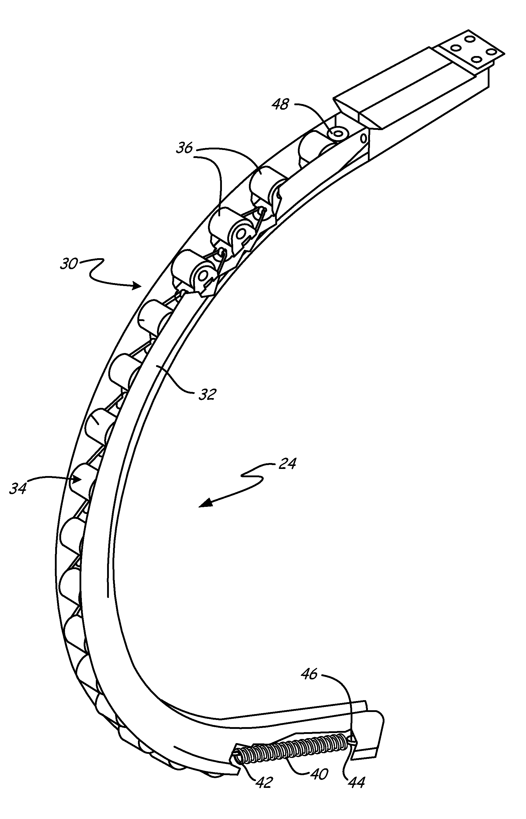
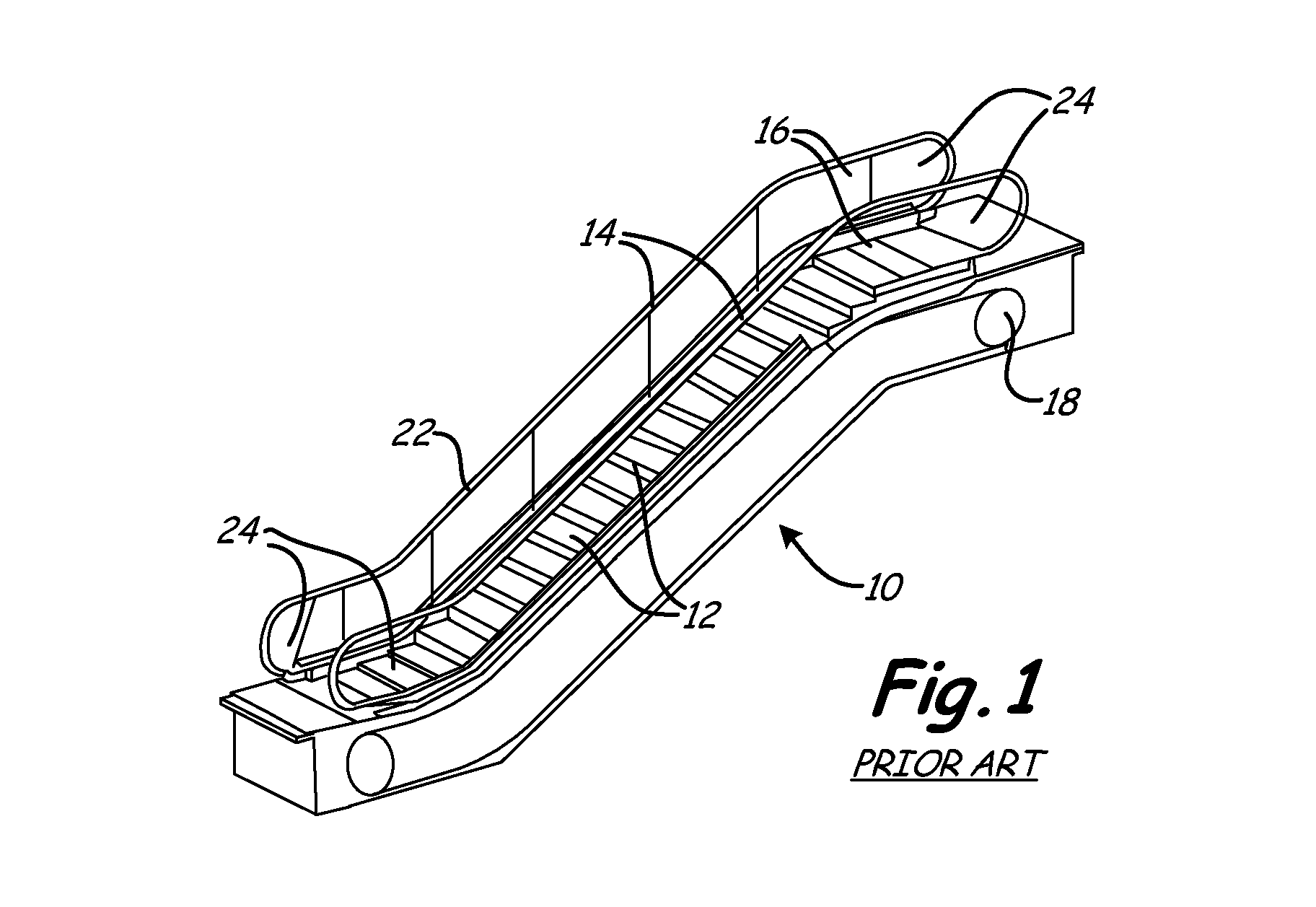
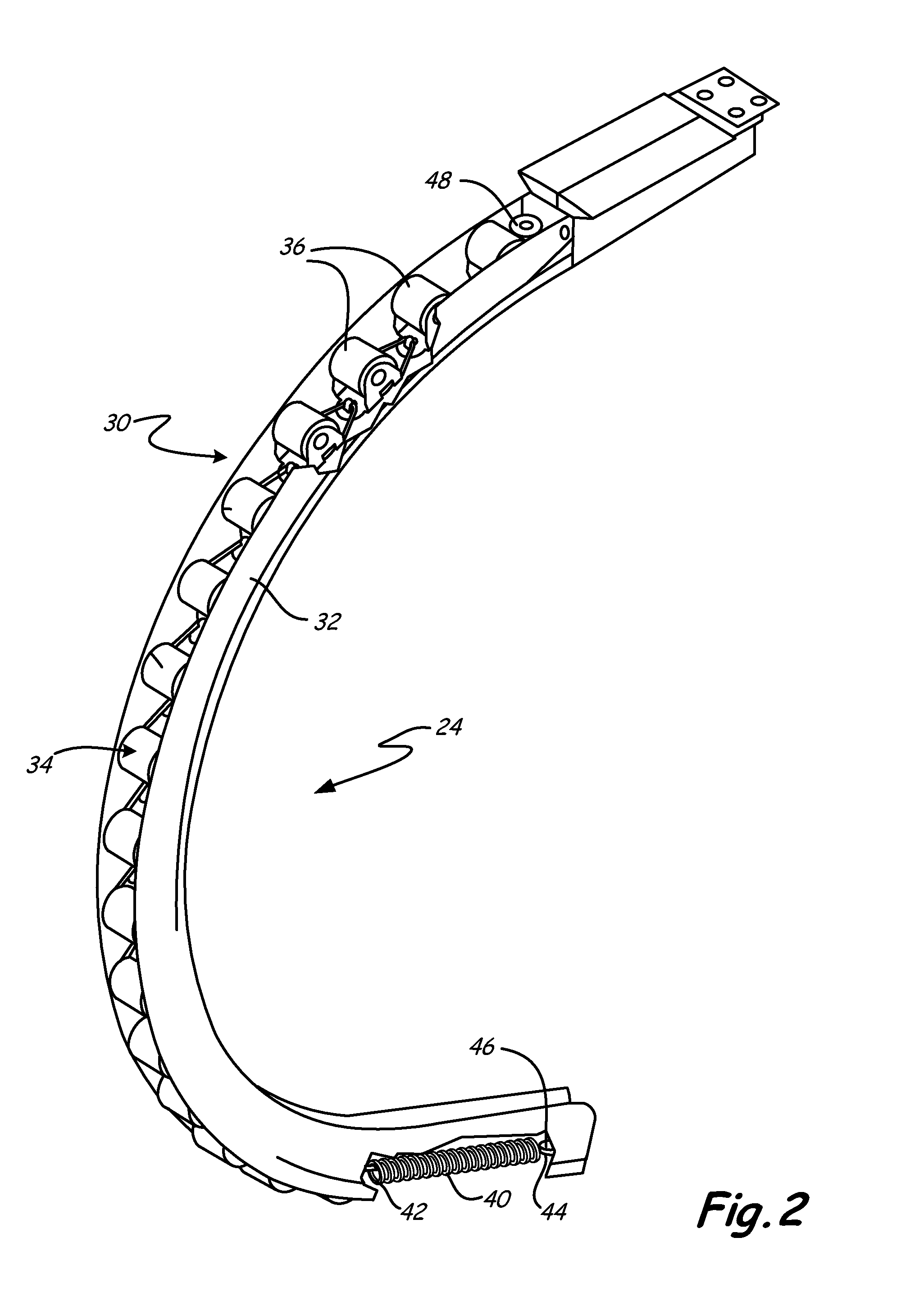
[0015] A passenger conveyor, such as escalator 10 shown in FIG. 1, includes a continuous loop of steps 12, a pair of handrails 14, a pair of balustrades 16 extending along the side of steps 12 from a first landing to a second landing, and a drive system 18. Drive system 18 is configured to drive steps 12 and handrails 14 at a constant speed and in synchrony with one another. Handrails 14 are slidingly engaged with handrail guide 22 disposed on the outer edge of each balustrade 16. Each end of balustrade 16 includes a rounded section that defines newel 24. Newel 24 extends beyond the exposed portion of steps 12 and provides a turn around section for reversing the direction of travel of handrail 14 for the return trip in the closed loop path through which handrail 14 travels. The newel 24 contains a roller bearing and newel guide assembly 30 (shown in FIG. 2) to enable the handrail 14 to pass around newel 24.
[0016] FIG. 2 shows a view of the roller bearing and newel guide assembly 30 of the present invention, having newel guide 32 and roller chain 34. Newel guide 32 has a curvilinear profile that mirrors the curvilinear profile of newel 24. Roller chain 34 includes a series of interlinked chain units 36. In order to maintain tension in roller chain 34, spring 40 has first end 42 that is attached to one end of roller chain 34 and second end 44 attached to one end of newel guide 32. Second end 44 is attached to newel guide 32 with fastener 46. Roller chain 34 is also attached to the other end of newel guide 32 with fastener 48.
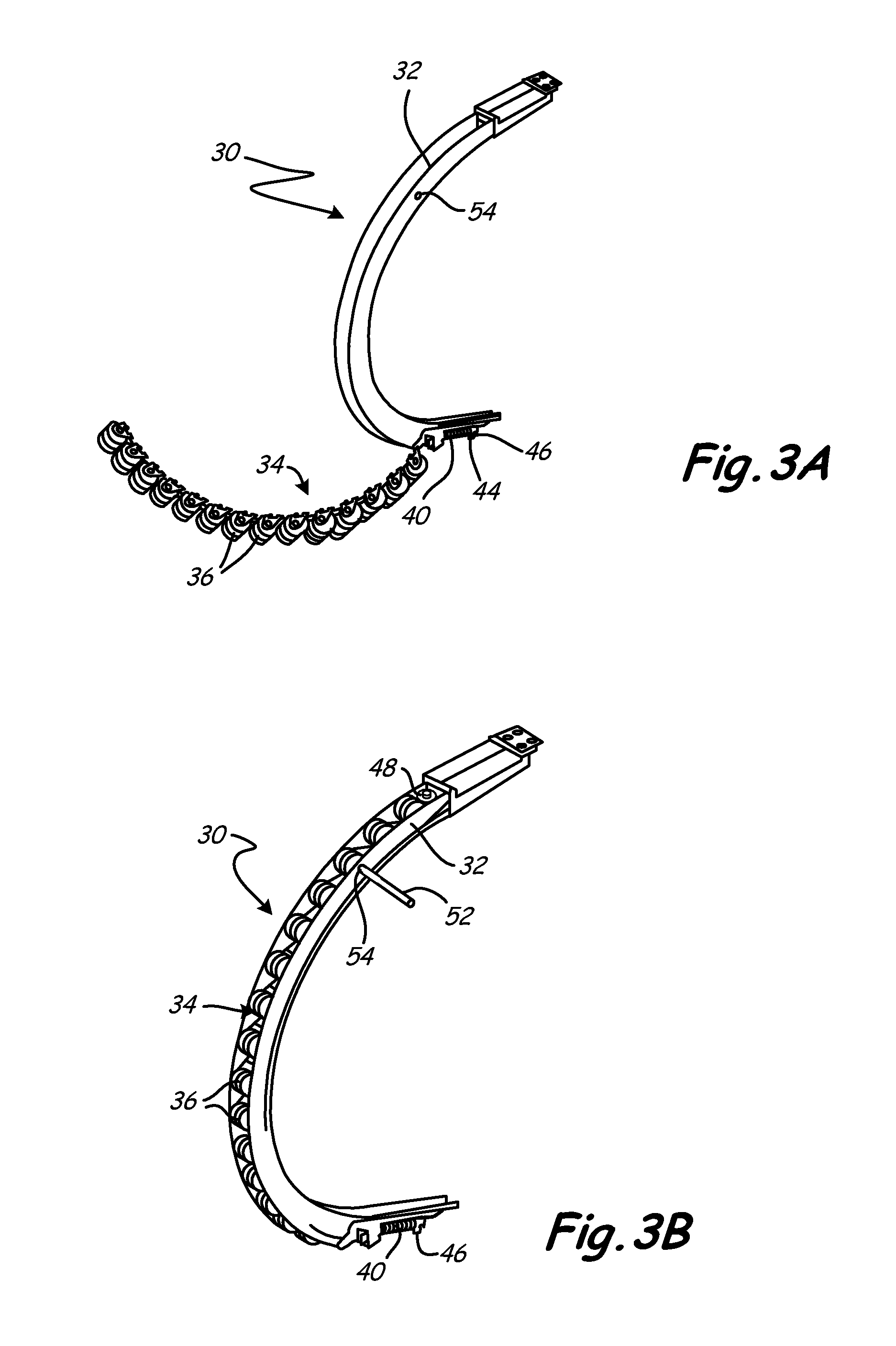
[0017] Due to the modular nature of roller chain 34, assembly and repair of the roller bearing and newel guide assembly 30 is simplified. FIGS. 3A and 3B show how roller chain 34 is assembled with newel guide 32 to form roller bearing and newel guide assembly 30. As mentioned above, second end 44 of spring 40 is joined at one end of newel guide 32 by fastener 46. Roller chain 34, which is connected to spring 40, is aligned with newel guide 32. Pin 52 is inserted into hole 54 which is pre-drilled within newel guide 32. Pin 52 allows tension in spring 40 to be maintained while roller chain 34 is fixed to newel guide 32 by fastener 48. To repair broken roller chain 34 (or even repair individual chain units 36 of roller chain 34), roller chain 34 is removed from newel guide 32 by releasing fasteners 46, 48. Repaired (or new) roller chain 34 can then be aligned with newel guide 32. Alternatively, at least one damaged chain unit 36 can be removed from the roller chain 34 and replaced with new chain unit 36 instead of using an entirely new roller chain 34.
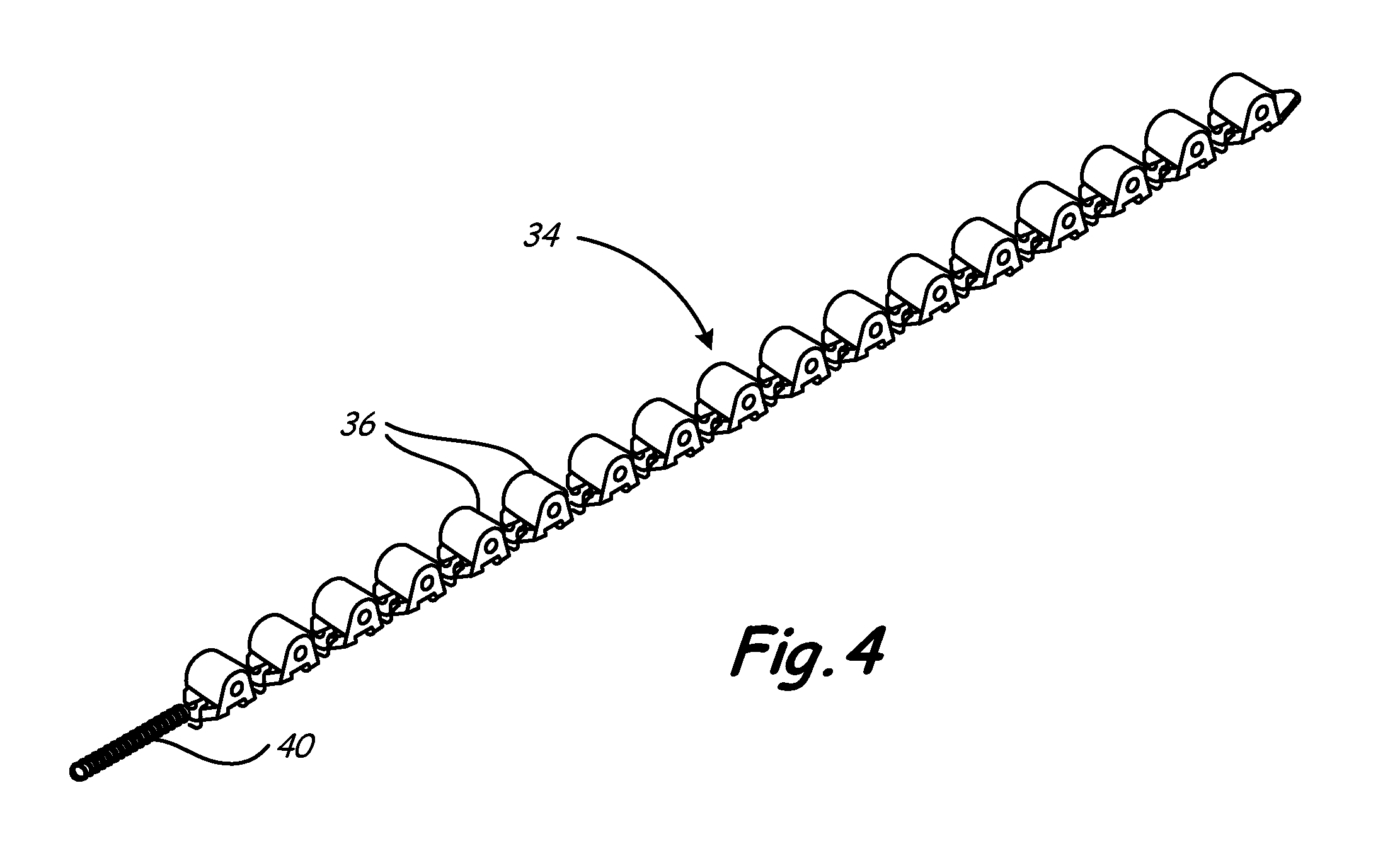
[0018] FIG. 4 shows a view of roller chain 34 removed from newel guide 32. Roller chain 34 typically includes at least ten chain units 36. Preferably, roller chain 34 has between fifteen and twenty chain units 36. The length of roller chain 34 is long enough to cover a substantial portion of newel guide 32 (shown in FIGS. 2-3) within newel 24 (shown in FIGS. 1-3). The overall length of roller chain 34, not including spring 40, can range between 600 mm (23.62 in.) and 1200 mm (47.25 in.), depending on the number of chain units 36. Typically, the length of roller chain 34 is between 800 mm (31.49 in.) and 1100 mm (43.31 in.).
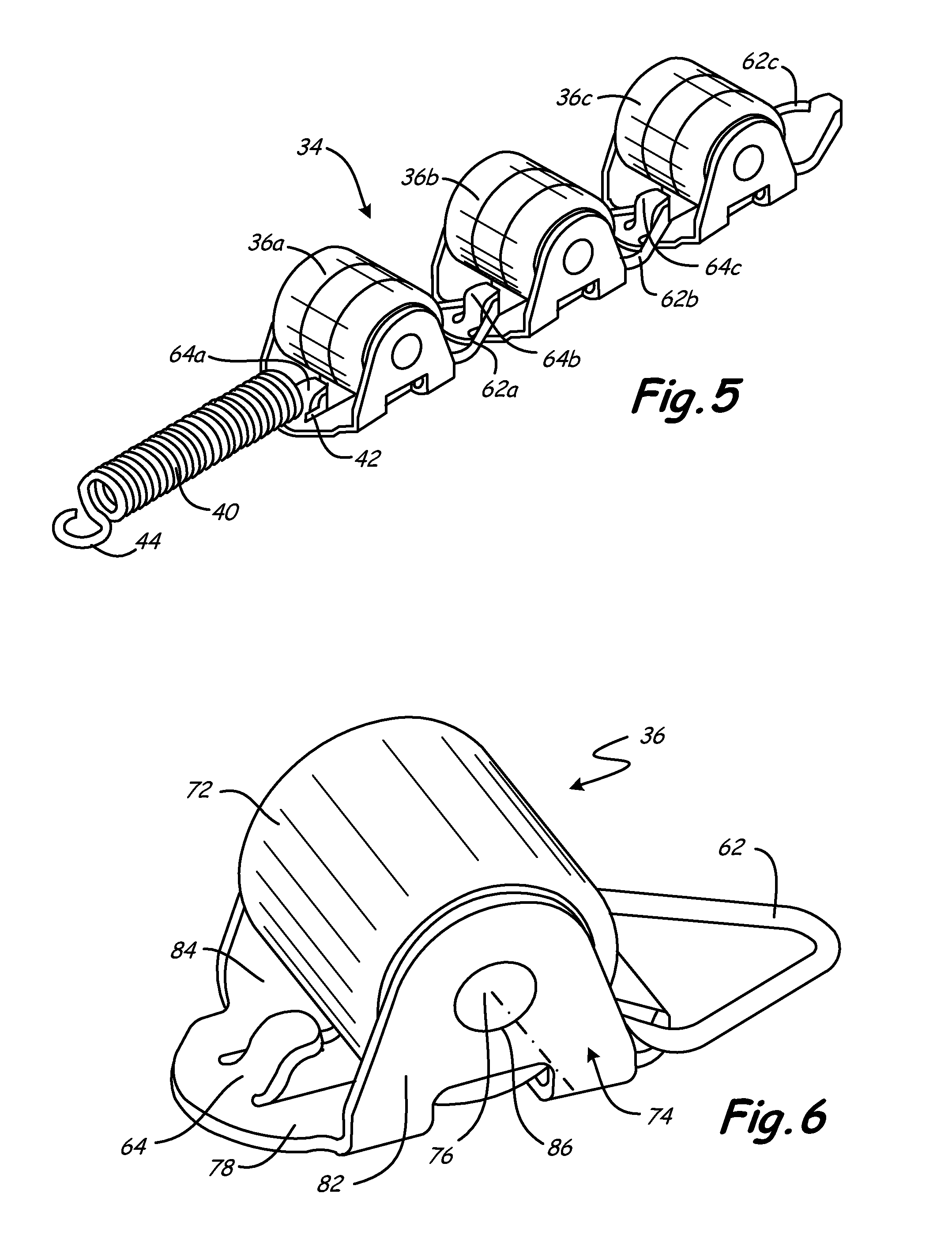
[0019] FIG. 5 shows a closer view of a portion of roller chain 34 shown in FIG. 4. As mentioned earlier, a series of interlinked chain units 36 forms roller chain 34. These chain units 36 are linked with each other using connectors 62, 64 in order to form roller chain 34. In the present embodiment, connector 62 is a loop and connector 64 is a hook. Other forms of connectors, such as ball and socket connectors and other male and female connectors, can also be used to form a mating connection between chain units 36. As shown in FIG. 5, chain unit 36a is connected to chain unit 36b by connecting loop 62a of chain unit 36a with hook 64b of chain unit 36b. Chain unit 36c is connected to chain unit 36b by connecting loop 62b of chain unit 36b with hook 64c of chain unit 36c. After a plurality of chain units 36a, 36b, 36c are connected to form roller chain 34, one end of roller chain 34 has free hook 64a, and the other end of roller chain 34 has free loop 62c. Spring 40 has first end 42 for connecting with roller chain 34 and second end 44 for connecting spring 40 to newel guide 32. In one embodiment, free hook 64a is connected to spring 40 at first end 42. However, it can be appreciated that spring 40 may instead be attached to free loop 62c.
[0020] As shown in FIG. 6, each chain unit 36 comprises roller bearing 72 held within frame 74 by pin 76. Roller bearing 72 has an inner race and an outer race (shown in FIGS. 8A-8C). Roller bearing 72 is typically made from metals, but may also be made from plastic or other polymeric materials. Frame 74 has base 78 and two side panels 82, 84 extending upward from base 78. Side panels 82, 84 extend upward from base 78 at opposite sides of base 78. Side panel 82 is substantially parallel with side panel 84. Side panels 82, 84 each have holes 86, 88. Pin 76 is inserted through hole 86, inner race of roller bearing 72, and hole 88 to support roller bearing 72 within frame 74. Hook 64 is connected to base 78 at one end of base 78, and loop 62 is connected at the opposite end of base of 78. Connectors, such has loop 62 and hook 64, may be integrally formed with frame 74 or may be detachable from frame 74. In the illustrative embodiment, hook 64 is formed integrally with frame 74, while loop 62 is made separately and later connected to frame 74. Loop 62 be pivotally connected to frame 74 so that roller chain 34 can follow the curvilinear profile of newel guide 32.
[0021] The overall length of chain unit 36 can range from 30 mm (1.18 in.) to 60 mm (2.36 in.), preferably between 40 mm (1.57 in.) and 50 mm (1.97 in.). The overall height of chain unit 36 can range from 10 mm (0.39 in.) to 40 mm (1.57 in.), preferably between 20 mm (0.79 in.) and 30 mm (1.18 in.). The overall width of chain unit 36 can range from 10 mm (0.39 in.) to 40 mm (1.57 in.), preferably between 25 mm (0.98 in.) and 35 mm (1.38 in.).
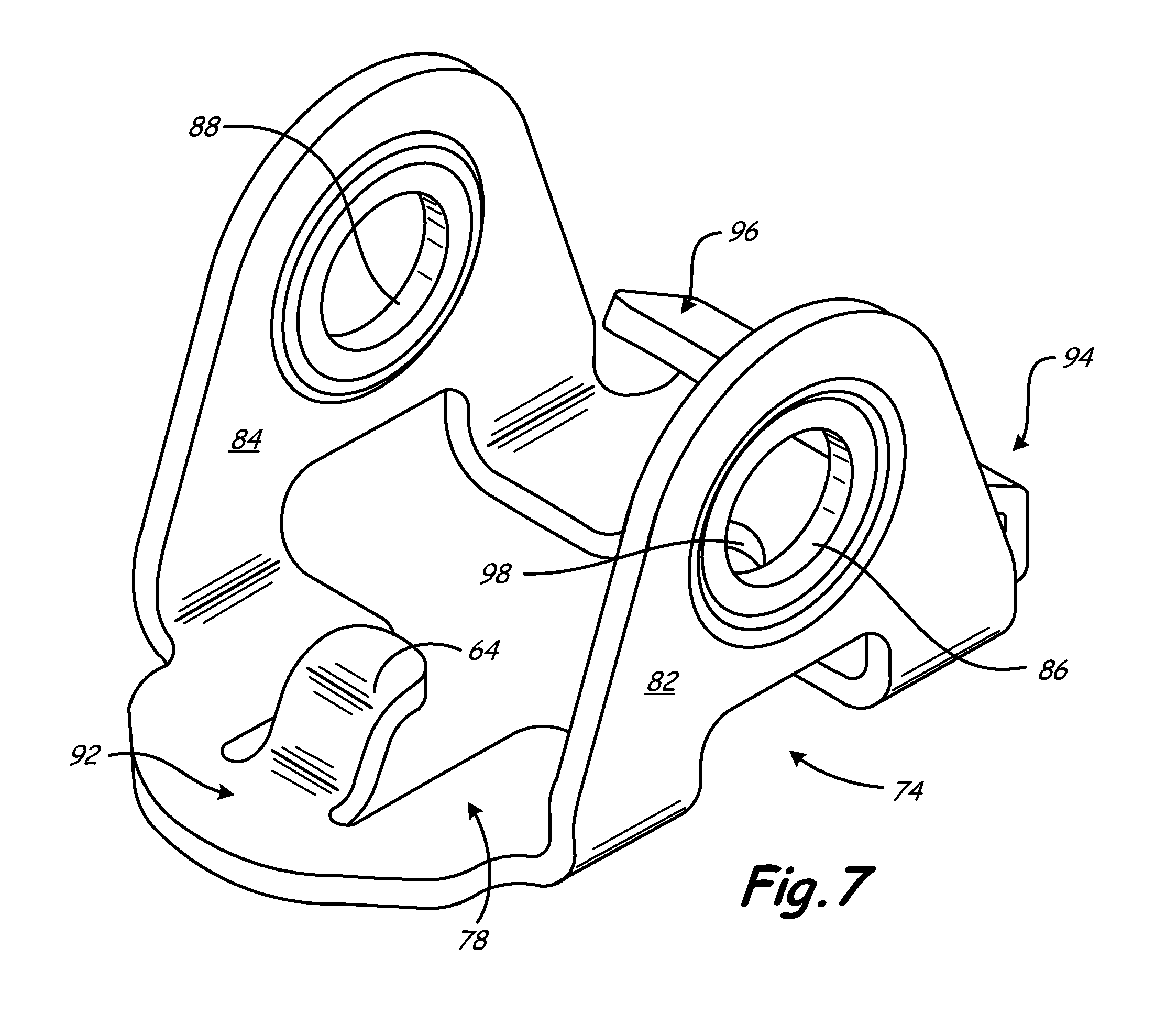
[0022] FIG. 7 shows a detailed view of frame 74 of one embodiment. At first end 92 of base 78, hook 64 is integrally formed with base 78. First end 92 of base 78 may also have a radius as shown in FIG. 7. Second end 94 of base 78 forms turnback 96, which is used to secure loop 62 (not shown) to the frame while allowing loop 62 to be pivotally coupled to frame 74. The distance between hook 64 and turnback 96 allows for clearance for roller bearing 72. Base 78 may have a notch 98 which is centered between side panels 82, 84. The purpose of notch 98 is to properly position frame 74 during manufacture. As previously mentioned, side panels 82, 84 extend upward from base 78 and have holes 86, 88. Side panels 82, 84 are substantially parallel to one another, and are rounded along at least a portion of their perimeter. Holes 86, 88 are concentric. Frame 74, including base 78 and side panels 82, 84, may be made of any material, including polymers and metals. In one embodiment, frame 74 is made from sheet metal, such as stainless steel or aluminum. Frame 74 may be manufactured by stamping, molding, and other casting methods, as well as other forms of metalworking, including, for example, welding.
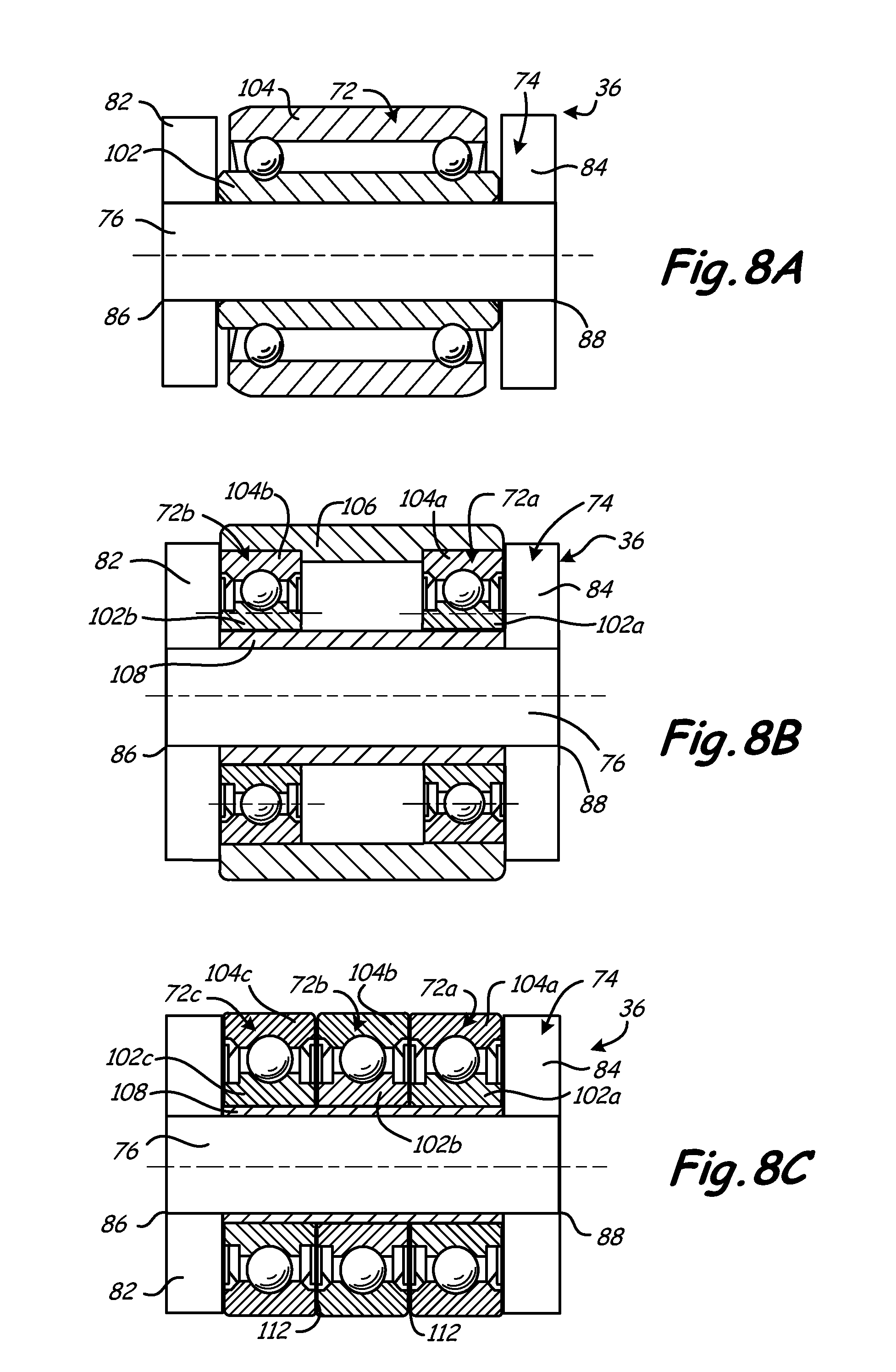
[0023] FIGS. 8A-8C show three embodiments of chain unit 36. It can be appreciated that other embodiments and configurations of the chain unit 36 may be used. Chain unit 36 may include a single roller bearing 72, as shown in FIG. 8A, or it may include a plurality of roller bearings 72a, 72b, 72c as shown in FIGS. 8B and 8C. Each roller bearing has an inner race 102 and an outer race 104.
[0024] In order to assemble chain unit 36 with single roller bearing 72, as shown in FIG. 8A, pin 76 is inserted through hole 86. Pin 76 then goes through inner race 102 and hole 88 to align roller bearing 72 within frame 74. Roller bearing 72 must be wide enough to maintain required contact between roller bearing 72 and handrail 14.
[0025] Where chain unit 36 has two roller bearings 72a, 72b, pin 76 goes through the inner race 102a, 102b of roller bearings 72a, 72b as shown in FIG. 8B. A roller shell 106 substantially surrounds the outer races 104a, 104b or roller bearings 72a, 72b in order to cover them. Roller shell 106 maintains the proper width of roller bearing 72a, 72b in order to have the necessary surface contact between roller bearing 72a, 72b and handrail 14. Bushing 108 may be inserted between pin 76 and inner races 102a, 102b of roller bearings 72a, 72b.
[0026] Where chain unit 36 has three roller bearings 72a, 72b, 72c, bushing 108 again may be inserted between pin 76 and inner races 102a, 102b, 102c of roller bearings 72a, 72b, 72c as shown in FIG. 8C. In the illustrative embodiment, bushing 108 is made from a plastic material. However, bushing 108 could also be made from metals (such as stainless steel and aluminum). In some embodiments, shims 112 are inserted between the roller bearings 72a, 72b, 72c. Shims 112 may be made from metals or polymers.
[0027] Although the present invention has been described with reference to particular embodiments, workers skilled in the art will recognize that changes may be made in form and detail without departing from the spirit and scope of the invention.
* * * * *
D00000
D00001
D00002
D00003
D00004
D00005
D00006
D00007
XML
uspto.report is an independent third-party trademark research tool that is not affiliated, endorsed, or sponsored by the United States Patent and Trademark Office (USPTO) or any other governmental organization. The information provided by uspto.report is based on publicly available data at the time of writing and is intended for informational purposes only.
While we strive to provide accurate and up-to-date information, we do not guarantee the accuracy, completeness, reliability, or suitability of the information displayed on this site. The use of this site is at your own risk. Any reliance you place on such information is therefore strictly at your own risk.
All official trademark data, including owner information, should be verified by visiting the official USPTO website at www.uspto.gov. This site is not intended to replace professional legal advice and should not be used as a substitute for consulting with a legal professional who is knowledgeable about trademark law.