Bottom Hole Assembly Comprising Flow Through Setting Tool And Frac Plug
Nard; Gary E. ; et al.
U.S. patent application number 12/545241 was filed with the patent office on 2011-12-29 for bottom hole assembly comprising flow through setting tool and frac plug. This patent application is currently assigned to THRU TUBING SOLUTIONS, INC.. Invention is credited to Michael L. Connell, Bryan F. McKinley, Gary E. Nard.
| Application Number | 20110315403 12/545241 |
| Document ID | / |
| Family ID | 45351444 |
| Filed Date | 2011-12-29 |

| United States Patent Application | 20110315403 |
| Kind Code | A1 |
| Nard; Gary E. ; et al. | December 29, 2011 |
BOTTOM HOLE ASSEMBLY COMPRISING FLOW THROUGH SETTING TOOL AND FRAC PLUG
Abstract
A bottom hole assembly comprising a hydraulic setting tool, a frac plug, and usually also an adapter for connecting the frac plug to the setting tool. The setting tool, adapter, and frac plug, all include continuous flow passages that allow fluid to be circulated in the well ahead of the plug as the bottom hole assembly is advanced. This removes debris present in the well and prevents the frac plug from becoming lodged in the well in other than the desired location. The setting tool includes a bypass feature that signals reliably when the plug has been successfully deployed. The bypass assembly comprises sliding members with bypass ports that can become aligned only when the collar on the frac plug has advanced far enough to ensure complete deployment of the frac plug.
| Inventors: | Nard; Gary E.; (Oklahoma City, OK) ; McKinley; Bryan F.; (Oklahoma City, OK) ; Connell; Michael L.; (Mustang, OK) |
| Assignee: | THRU TUBING SOLUTIONS, INC. Oklahoma City OK |
| Family ID: | 45351444 |
| Appl. No.: | 12/545241 |
| Filed: | August 21, 2009 |
| Current U.S. Class: | 166/387 ; 166/179 |
| Current CPC Class: | E21B 33/128 20130101; E21B 23/06 20130101; E21B 33/12 20130101 |
| Class at Publication: | 166/387 ; 166/179 |
| International Class: | E21B 33/128 20060101 E21B033/128; E21B 23/04 20060101 E21B023/04; E21B 23/06 20060101 E21B023/06; E21B 33/12 20060101 E21B033/12; E21B 23/00 20060101 E21B023/00 |
Claims
1. A bottom hole assembly for connection to the end of a well conduit having a fluid flow passage therethrough, the assembly comprising: a frac plug having a downhole end and an uphole end and a flow passage extending therebetween for passing fluid through the plug; a hydraulic setting tool having a downhole end and an uphole end and a flow passage extending therebetween for passing fluid through the tool; wherein the uphole end of the frac plug is connected to the downhole end of the setting tool so that the flow passage in the setting tool is in fluid communication with the flow passage in the frac plug.
2. The bottom hole assembly of claim 1 further comprising an adapter for connecting the setting tool to the frac plug, wherein the adapter comprises a flow passage for passing fluid through the adapter.
3. A method for setting a frac plug, comprising: flowing fluid through the frac plug as it is advanced down the well.
4. A setting tool for use with a well conduit to activate a downhole tool, the downhole tool comprising a stationary member and a sliding member, the setting tool comprising: an upper housing assembly having an upper end, the upper end being connectable to a well conduit; a piston mandrel assembly with an upper end connectable to the upper housing assembly and a lower end connectable to the stationary member of the downhole tool so as to prevent axial movement therebetween; a slide assembly comprising a sleeve engageable with the sliding member of the downhole tool and slidably supported on the piston mandrel for movement relative thereto along a selected range of travel from a retracted position to an extended position, wherein the range of travel is sufficient to activate the downhole tool; a hydraulic system configured to drive the movement of the slide assembly to complete the range of travel; a bypass assembly comprising a plurality of ports movable between aligned and non-aligned positions, wherein in the aligned positions, the ports allow release of hydraulic fluid from the hydraulic system sufficient to produce a rapid and substantial pressure drop, wherein the bypass assembly is configured to align the ports when the sleeve in the slide assembly has completed the selected range of travel.
5. The setting tool of claim 4 wherein the setting tool is characterized by a flow passage extending therethrough and wherein the downhole tool is a frac plug with a flow passage extending therethrough that is continuous with the flow passage in the setting tool and with the conduit.
Description
FIELD OF THE INVENTION
[0001] The present invention relates generally to setting frac plugs in oil and gas wells.
BRIEF DESCRIPTION OF THE DRAWINGS
[0002] FIG. 1 is a side elevational view of a bottom hole assembly constructed in accordance with the present invention.
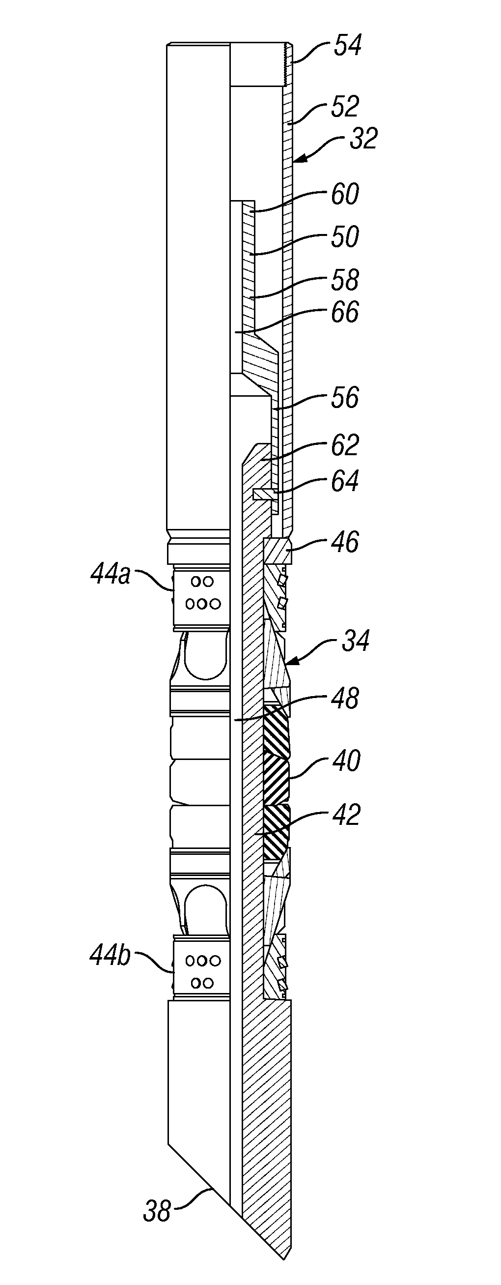
[0003] FIG. 2 is a longitudinal, partly sectional view of a conventional frac plug connected to an adapter with a flow passage made in accordance with the present invention.
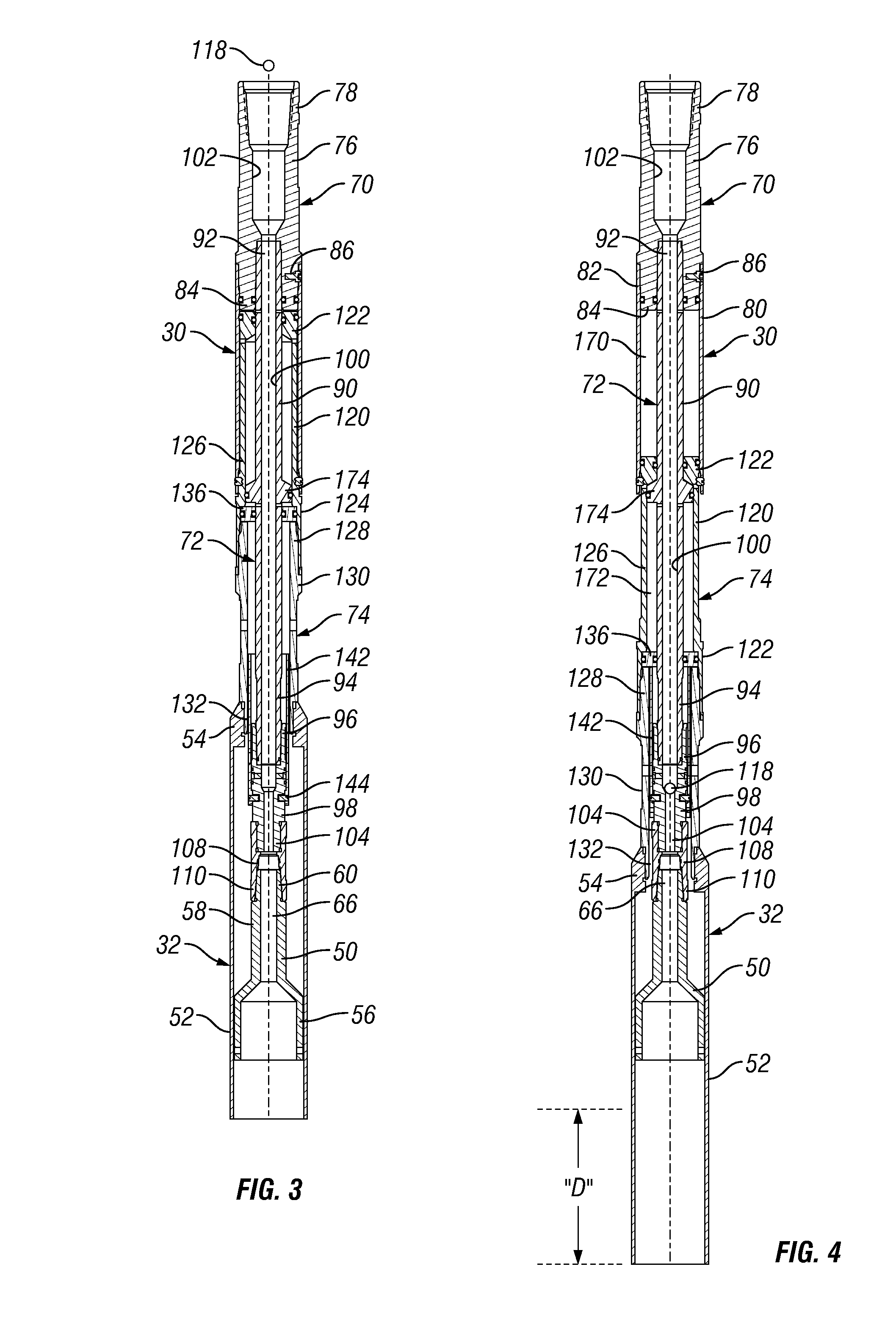
[0004] FIG. 3 is a longitudinal sectional view of a setting tool and adapter made in accordance with the present invention. The tool is shown in the retracted or neutral position.
[0005] FIG. 4 is a longitudinal sectional view of the setting tool and adapter shown in FIG. 3 illustrating the extended position used to deploy the frac plug.
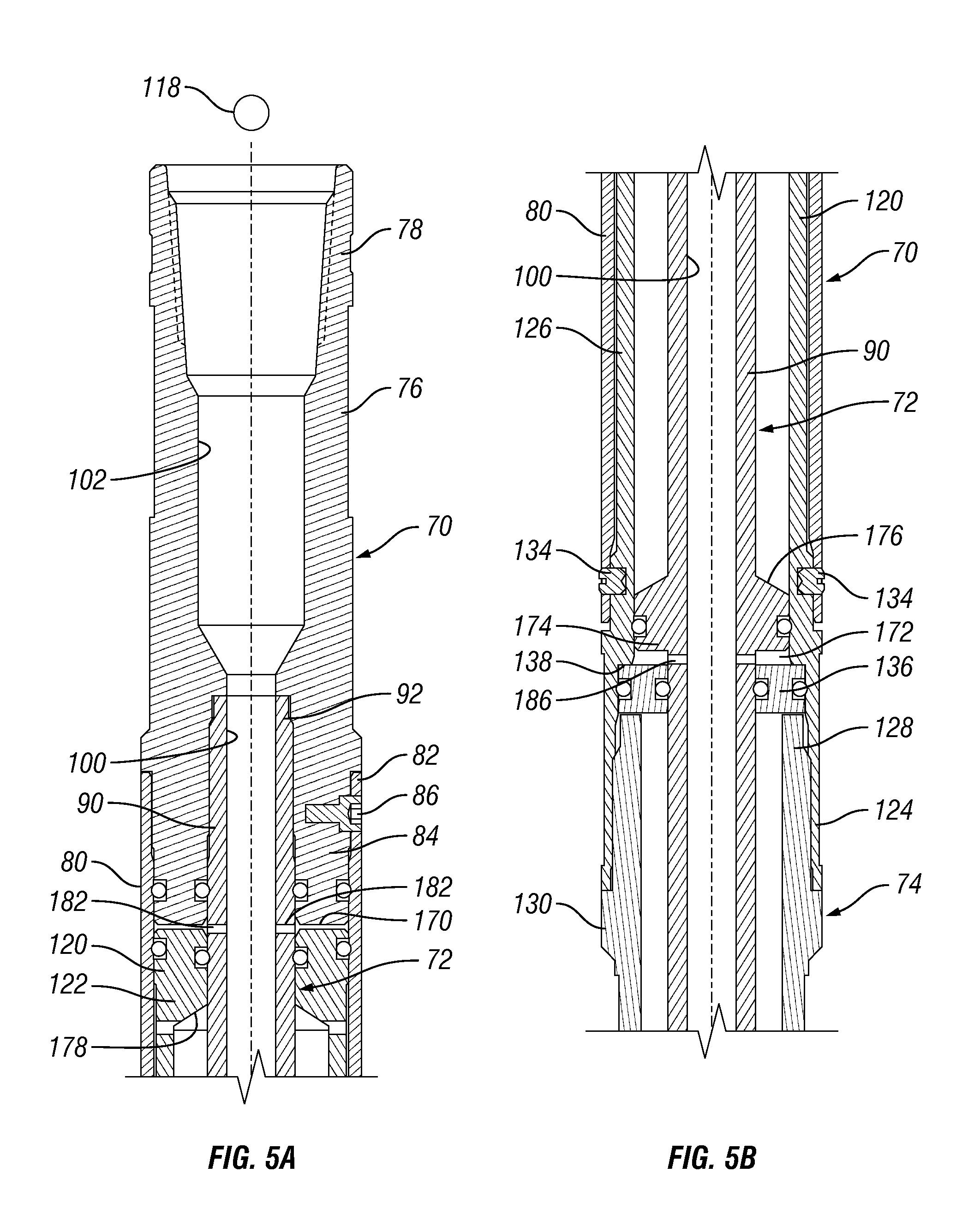
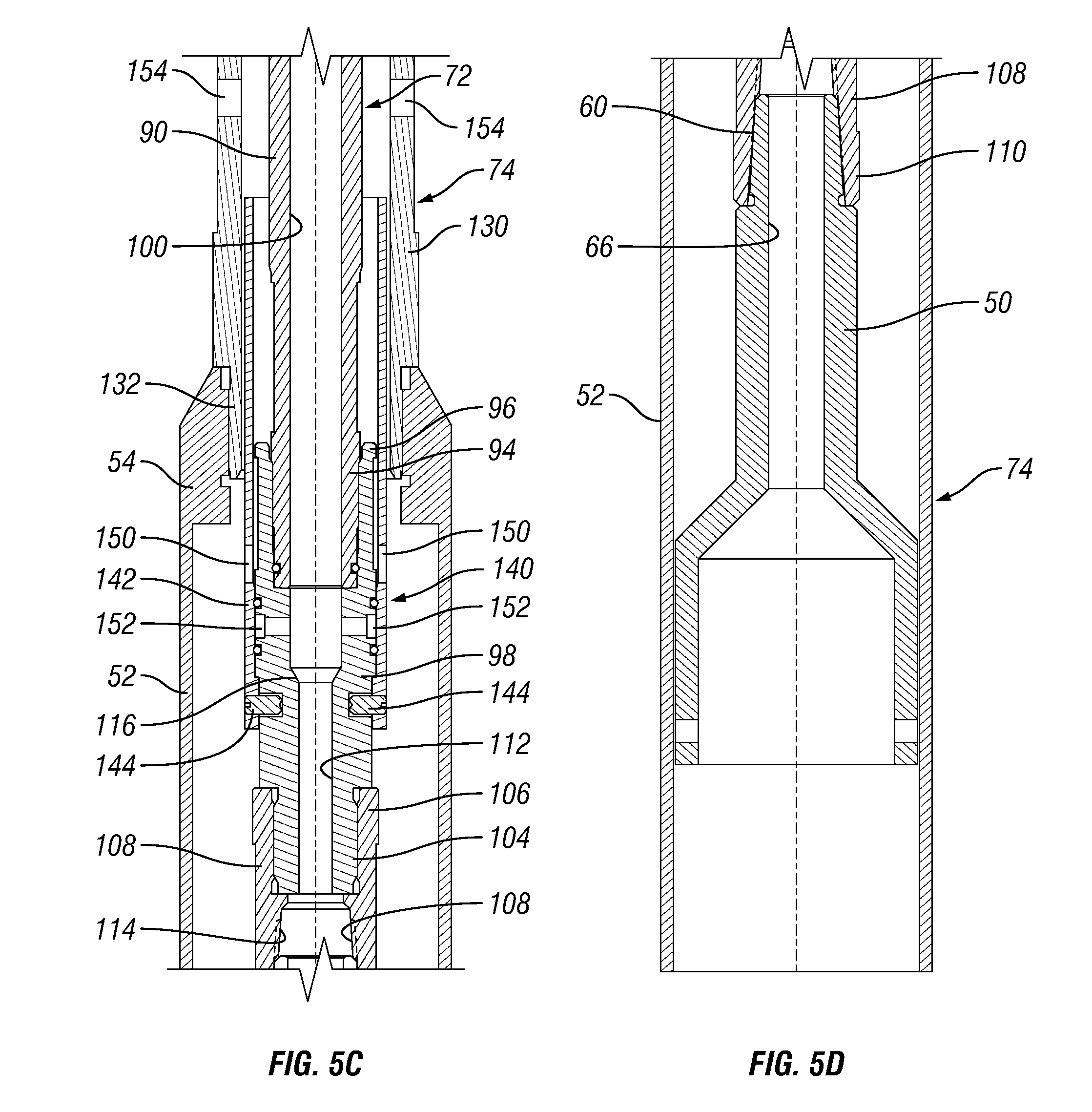
[0006] FIGS. 5A-5D show an enlarged, longitudinal sectional view of the setting tool and adapter shown in FIG. 3.
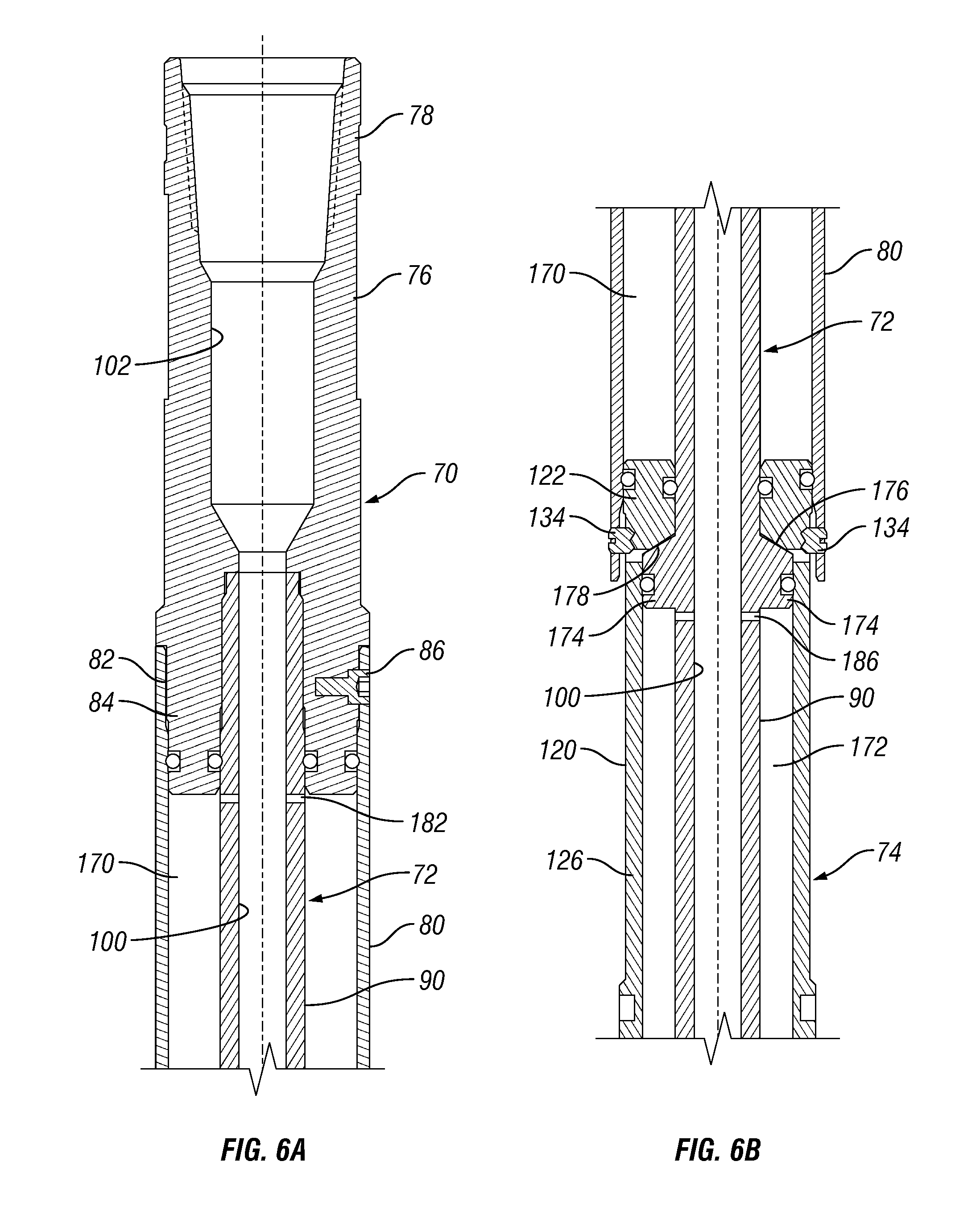
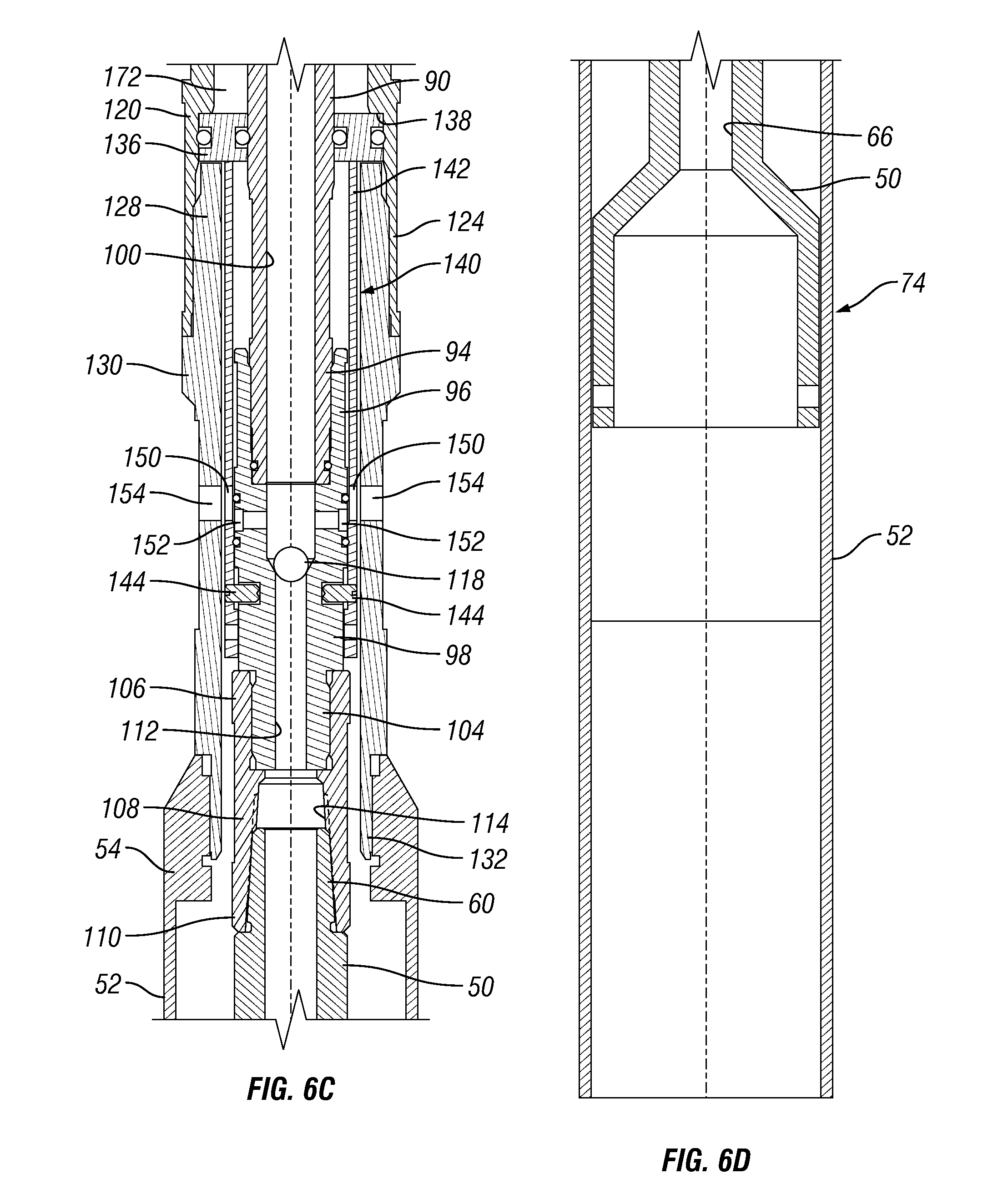
[0007] FIGS. 6A-6D show an enlarged, longitudinal sectional view of the setting tool and adapter shown in FIG. 4.
DETAILED DESCRIPTION OF THE PREFERRED EMBODIMENT(S)
[0008] Frac and bridge plugs are used to isolate zones in a well. Plugs typically are placed in position using a setting tool, such as a hydraulic setting tool. The frac plug is attached to the setting tool which is then run downhole on coiled tubing, jointed pipe or other conduit. It is not unusual to encounter debris as the plug is advanced down the well. This debris tends to collect ahead of the bottom hole assembly ("BHA") and may slow or even block proper positioning of the plug.
[0009] Some frac plugs have a flow passage that allows fluid to pass up through the plug from the well below after the plug is set. The present invention takes advantage of this flow passage by employing a hydraulic setting tool with a flow passage to provide fluid communication through the entire BHA as the plug is being advanced. Thus, fluid can be circulated through the well to wash away debris as the plug is advanced to the selected location in the well.
[0010] Setting tools are used to set a variety of plugs and packing devices. One difficulty associated with setting such devices is determining when and if the plug or device has been completely and successfully deployed. The setting tool of the present invention incorporates a fluid bypass system that reliably indicates successful deployment of the plug or other device by producing a precipitous drop in the hydraulic pressure. This is accomplished by using a system of fluid bypass ports that become aligned only when the sliding component of the setting tool has traveled a distance sufficient to completely set the plug.
[0011] Turning now to the drawings in general and to FIG. 1 in particular, there is shown therein a bottom hole assembly constructed in accordance with a preferred embodiment of the present invention and designated generally by the reference numeral 10. As used herein, "bottom hole assembly" or "BHA" refers to a combination of tool members connected to the end of coiled tubing, string of pipe joints, or other well conduit for performing one or more operations downhole.
[0012] The BHA 10 shown in FIG. 1 is adapted for connection to coiled tubing (not shown) and therefore the uppermost component is a coiled tubing connector 12. Next is a flapper valve 14, hydraulic disconnect 16, eccentric weight bar or sub 20, and an oriented perforator 22. Beneath the oriented perforator 22 is a hydraulic setting tool 30 and an adapter 32, both made in accordance with the present invention, as well be explained below. Finally, connected to the adapter 32 is a conventional frac plug 34 of the type that has a flow passage through it. It will be understood that this BHA 10 is only an example of the type of tools and components that may be combined in a BHA. The number and type of tools and connectors will vary widely depending on the well and the nature of the operations to be performed.
[0013] The adapter 32 and frac plug 34 are shown in more detail in FIG. 2. The frac plug 34 generally comprises rubber packer elements 40 mounted on a plug mandrel 42 between slips 44a and 44b. In a known manner, when the slips 44a and 44b are moved closer together by force on an upper ring or collar 46, the packer elements 40 are squeezed outwardly until they frictionally engage in the side of the well casing (not shown). The plug mandrel 42 is tubular defining a flow passage 48 extending the length of the plug and exiting the lower, open end 38.
[0014] The adapter 32 comprises an inner tension mandrel 50 and an outer sleeve 52. The uphole end 54 of the sleeve 52 is threaded for connection to the setting tool 30, as will be described in more detail hereafter. The tension mandrel 50 is tubular with a wider lower portion 56 and a narrower upper portion 58. The upper portion 58 has a threaded end 60 for connection to the setting tool 30 as described further below. The lower portion 56 is sized to slidingly receive the upper end 62 of the plug mandrel 42 and is connected thereto by at least one and preferably a plurality of shear pins or screws, designated collectively at 64. By way of example only, the shear screws 64 may comprise 5 shear screws, each having a maximum shear strength of 5000 pounds so that 30,000 pounds of force is required to break them and release the frac plug. The inner bore or lumen 66 of the tension mandrel 50 forms a flow passage therethrough continuous with the flow passage 48 in the plug 34.
[0015] It should be noted that an adapter is not essential to the present invention. Rather, in some instances a setting tool may be designed to be connected directly to the frac plug (or other device). That is, the components required to connect the setting tool to the frac plug may be incorporated in the setting tool. However, as is well known in the art, the use of an adaptor permits a particular setting tool to be used with multiple sizes and types or plugs.
[0016] The preferred setting tool 30 connected to the adapter assembly 32 is shown in FIGS. 3 and 4 and also FIGS. 5A-5D and 6A-6D. FIGS. 3 and 5A-5D show the setting tool 30 in the retracted or undeployed position. FIGS. 4 and 6A-6D show the setting tool 30 in the extended or deployed position. The setting tool 30 comprises an upper housing assembly 70, a mandrel assembly 72, and a slide assembly 74.
[0017] The upper housing assembly 70 preferably comprises a top sub 76 with an uphole end 78 threadedly connectable to the well conduit (not shown) or to another BHA component, such as the oriented perforating tool 22 (FIG. 1). The upper housing assembly 70 also preferably comprises an upper housing 80, the uphole end 82 of which is connected to the downhole end 84 of the top sub 76 by a set screw 86 (FIGS. 5A & 6A).
[0018] In the preferred embodiment, the mandrel assembly 72 comprises a plurality of tubular components all axially fixed relative to the upper housing assembly 70. An elongated tubular piston mandrel 90 is connected at is uphole end 92 to the downhole end 84 of the top sub 76. The piston mandrel 90 is threadedly connected at its downhole end 94 to the uphole end 96 of a circulating sub 98 (FIGS. 5C & 6C). As best seen in FIGS. 3 and 4, the lumen 100 of the mandrel 90 forms a flow passage that extends the length of the mandrel and connects to the flow passage 102 extending through the top sub 76.
[0019] As best seen in FIGS. 5C and 6C, the downhole end 104 of the circulating sub 98 is threadedly connected to the uphole end 106 of a bottom sub 108. The downhole end 110 of the bottom sub 108 is threadedly connected to the uphole end 60 of the tension mandrel 50. A flow passage 112 extends the length of the circulating sub 98, and a flow passage 114 extends the length of the bottom sub 108. The flow passage 112 in the circulating sub 98 defines a ball seat 116 (FIG. 5C) to receive a ball 118 (FIGS. 3, 4 and 6C), for a purpose yet to be described.
[0020] Referring still to FIGS. 3, 4, 5A-5D, and 6A-6D, the slide assembly 74 comprises an upper piston 120 with an annular head 122, a lower end 124 and a tubular body 126 therebetween. The lower end 124 (FIG. 5B) is threadedly connected to the upper end 128 of a push sleeve 130. The lower end 132 of the push sleeve 130 is connected to the upper end 54 of the adapter sleeve 52 (FIGS. 5C & 6C). As seen in FIGS. 5B & 6C, the piston body 126 is temporarily fixed against axial movement relative to the upper housing assembly 70 by one or more shear screws 134. A lower piston 136 is carried on the upper end 128 of the push sleeve 130, being captured by a shoulder 138 in the inner sidewall of the piston body 126.
[0021] As best shown in FIGS. 5C and 6C, the setting tool 30 further comprises a bypass assembly 140. The bypass assembly 140 comprises a bypass sleeve 142 slidably supported on the circulation sub 98. The bypass sleeve 142 is temporarily fixed against axial movement relative to the circulation sub 98 by means of shear screws or pins 144.
[0022] A plurality of ports 150 are formed in the bypass sleeve 142. Ports 152 are also formed in the circulation sub 98. Ports 154 are formed in the push sleeve 130. The ports 150, 152, and 154 are sized and positioned to be alignable with each other when the slide assembly 74 is moved axially a selected distance "D" (FIG. 4) on the piston mandrel 90. The alignment of the ports then forms a continuous flow path from the lumen 100 inside the tubular piston mandrel 90 through the sides of the circulation sub 98, the bypass sleeve 142, and the push sleeve 130, as will be explained more fully below.
[0023] The above-described components of the setting tool 30 are configured to provide a hydraulic system 160 for driving axial movement of the slide assembly 74. The preferred configuration for the hydraulic system 160 includes an upper fluid chamber 170, which contains the head 122 of the upper piston 120, and a lower fluid chamber 172, which contains the lower piston 136. The piston mandrel 90 includes an annular flange 174 along its length to form a divider between the upper and lower chambers 170 and 172. As seen in FIGS. 5B and 6B, the upper face of the flange 174 forms an inclined shoulder 176 that engages a complimentary lower face 178 on the piston head 122.
[0024] The upper chamber 170 (FIGS. 6A & 6B) is defined by the inner diameter of the upper housing 80 and the outer diameter of the piston mandrel 90 above the annular flange 174 of the piston mandrel 90. O-rings (unnumbered) seal the upper chamber 170 between the upper end 82 of the upper housing 80 and the lower end 84 of the top sub 76. Similarly, O-rings (unnumbered) seal the interface between the piston head 122 and the upper end 82 of the upper housing 80 and between the annular flange 174 and the lower end 124 of the upper piston 120. Ports 182 near the upper end 92 of the piston mandrel 90 provide fluid communication between the lumen 100 of the piston mandrel and the upper fluid chamber 170 (FIGS. 5A and 6A).
[0025] The lower chamber 172 is defined by the inner diameter of the upper piston body 126 and the outer diameter of the piston mandrel 90 below the annular flange 174. Ports 186 (FIGS. 5B & 6B) in the piston mandrel 90 below the annual flange 174 provide fluid communication between the lumen 100 of the piston mandrel 90 and the lower fluid chamber 172.
[0026] Having described the structure of the preferred BHA 10, its operation now will be described with continued reference to FIGS. 3, 4, 5A-5D, and 6A-6D. First, the frac plug 34 is positioned at the selected level in the well (not shown). As the plug is advanced down the well, fluid is pumped through the BHA 10 to flush the well ahead of the plug 34 to prevent debris or other matter in the well from obstructing the proper placement of the plug. Now it will be understood that the flow passages 102, 100, 112, and 108 all provide a continuous flow path through the BHA 10 so that fluid exiting the open end 38 of the frac plug 34 (FIG. 2) flushes debris.
[0027] Once the plug 34 is positioned at the correct level, a ball 118 (FIGS. 5A & 6C) is pumped down conduit to the BHA. When the ball 118 is seated in the ball seat 116, fluid flow through the circulation sub 98, bottom sub 108, adapter 32, and frac plug 34 stops. Consequently, pressure begins to build inside the piston mandrel 90, forcing fluid to flow through the ports 182 and 186 in the upper and lower fluid chambers 170 and 172. This exerts force on the head 122 of the upper piston 120 and on the lower piston 136, breaking the shear pins 134 between the upper housing 80 and the upper piston 120. These may be relatively weak pins, preferably having a maximum shear strength of only about 1000 pounds. The primary purpose of these pins is to keep the slide assembly 74 from deploying partially as the BHA is run downhole.
[0028] Once the shear pins 134 have broken, the slide assembly 74 moves downward in response to the force on the piston head 122 and the lower piston 136. After several inches of travel, the frac plug 34 will be fully deployed. In most instances, 4-5 inches of travel will be sufficient to set the plug 34.
[0029] The slide assembly 74 continues to move downwardly until the lower piston 136 engages the upper end of the bypass sleeve 142. The force on the sleeve 142 increases until sufficient to break the shear pins 144, whereupon the slide assembly 74 completes its full travel distance "D" (FIG. 4). In this position, the ports 152 in the circulation sub 98 and the ports 150 in the bypass sleeve 142 are aligned with the ports 154 in the push sleeve 130.
[0030] The aligned ports 150, 152, and 154 allow a sudden increase in the flow of fluid out of the tool, causing a dramatic drop in the pressure reading at the wellhead (not shown). As used herein, "rapid and substantial pressure drop" refers to a pressure drop that is sudden and large enough to be readily perceived by the well operator and sufficient to signal to the operator that the setting operation is completed. By way of example only, in the preferred setting tool, alignment of the ports should produce at least about a 2000 psi pressure drop in a bout fifteen seconds.
[0031] Having successfully deployed the frac plug 34, the frac plug is disengaged from the BHA. Continued pressure from the hydraulic system breaks the shear pins 64 between the tension mandrel 50 in the adapter 32 and the plug mandrel 42, releasing the connection between the BHA and the plug 34. Thereafter, the BHA may be withdrawn from the well.
[0032] For the purpose of this description, the words left, right, front, rear, top, upper, lower, inward, outward, uphole, downhole, bottom, up, upwardly, down, downwardly, inside, and outside may be used to describe the various parts and relative positions of structures and operations in the present invention as depicted in the drawings. These descriptive terms should not be considered as limiting the possible orientations of the invention or how it may be used.
[0033] Now it will be appreciated that the present invention provides frac plug setting tools and methods that offer many advantages. The bottom hole assembly provides a "flow through" function that allows fluid to be circulated through the well ahead of the frac plug as it is being advanced toward the desired location. The setting tool includes a bypass feature that is mechanically simple and reliably signals the successful deployment of the plug. As regards the setting tool, it should be noted that a setting tool with this bypass function is useful in operations other than setting frac plugs and with or without the "flow through" feature.
[0034] The embodiments shown and described above are exemplary. Many details are often found in the art and, therefore, many such details are neither shown nor described herein. It is not claimed that all of the details, parts, elements, or steps described and shown were invented herein. Even though numerous characteristics and advantages of the present inventions have been described in the drawings and accompanying text, the description is illustrative only. Changes may be made in the details, especially in matters of shape, size, and arrangement of the parts within the principles of the inventions to the full extent indicated by the broad meaning of the terms of the attached claims. The description and drawings of the specific embodiments herein do not point out what an infringement of this patent would be, but rather provide an example of how to use and make the invention. Likewise, the abstract is neither intended to define the invention, which is measured by the claims, nor is it intended to be limiting as to the scope of the invention in any way. Rather, the limits of the invention and the bounds of the patent protection are measured by and defined in the following claims.
* * * * *
D00000
D00001
D00002
D00003
D00004
D00005
D00006
XML
uspto.report is an independent third-party trademark research tool that is not affiliated, endorsed, or sponsored by the United States Patent and Trademark Office (USPTO) or any other governmental organization. The information provided by uspto.report is based on publicly available data at the time of writing and is intended for informational purposes only.
While we strive to provide accurate and up-to-date information, we do not guarantee the accuracy, completeness, reliability, or suitability of the information displayed on this site. The use of this site is at your own risk. Any reliance you place on such information is therefore strictly at your own risk.
All official trademark data, including owner information, should be verified by visiting the official USPTO website at www.uspto.gov. This site is not intended to replace professional legal advice and should not be used as a substitute for consulting with a legal professional who is knowledgeable about trademark law.