Compositions And Method For Use In Plugging A Well
Streetman; Foy
U.S. patent application number 12/823774 was filed with the patent office on 2011-12-29 for compositions and method for use in plugging a well. Invention is credited to Foy Streetman.
| Application Number | 20110315381 12/823774 |
| Document ID | / |
| Family ID | 45351432 |
| Filed Date | 2011-12-29 |


| United States Patent Application | 20110315381 |
| Kind Code | A1 |
| Streetman; Foy | December 29, 2011 |
COMPOSITIONS AND METHOD FOR USE IN PLUGGING A WELL
Abstract
A composition for use in plugging a well includes a mud having a plurality of plugging members therein, wherein the plugging member has a density more than about eight times that of water. A method of providing the composition into the well is also provided.
| Inventors: | Streetman; Foy; (Chickasha, OK) |
| Family ID: | 45351432 |
| Appl. No.: | 12/823774 |
| Filed: | June 25, 2010 |
| Current U.S. Class: | 166/292 ; 523/130 |
| Current CPC Class: | E21B 33/138 20130101; E21B 21/003 20130101 |
| Class at Publication: | 166/292 ; 523/130 |
| International Class: | E21B 33/13 20060101 E21B033/13 |
Claims
1. A composition for use in plugging a well, which includes a mud having a plurality of plugging members therein, wherein each said plugging member has a density more than about eight times that of water.
2. The composition of claim 1, wherein said plugging element includes an inner core and an outer cover.
3. The composition of claim 2, wherein at least one of said inner core and said outer cover includes a heavy material having a density of more than about eight to twenty times that of water.
4. The composition of claim 3, wherein said outer cover includes a drag reducing material.
5. The composition of claim 3, wherein said outer cover includes a dissolvable material.
6. The composition of claim 3, wherein said plugging member includes an expanding polymer.
7. A method for plugging a well, which includes the steps of: (a) providing a composition including mud having a plurality of plugging members therein, wherein the plugging member has a density more has a density more than about eight times that of water; and (b) providing said composition in sufficient opposing fluid flow to fluid flow from an uncontrolled well flow such that said plugging members are enabled to drop by virtue of gravity to a perforation zone where said plugging members impede well flow from said perforation zone.
8. The method of claim 7, wherein step (b) is further characterized to include inserting tubing into said well and delivering said composition through said tubing.
9. The method of claim 8, wherein said step (b) is further characterized to provide said tubing in said well to a point adjacent a perforation in said well.
10. The method of claim 7, wherein said step (a) is further characterized to provide a stream of mud under pressure through a conduit and introduce said plugging members into said conduit through a valve chamber communicably connected to said conduit.
11. The method of claim 10, wherein said valve chamber is characterized to be include a top valve and a lower valve and wherein when said lower valve closed, top valve is open to fill said chamber with said plugging members, then said top valve is closed and said lower valve is opened to permit said plugging members to mix with said mud.
12. The method of claim 7, wherein step (b) is further characterized to include employing a blow out preventer over said well and delivering said composition through said blow out preventer.
13. The method of claim 7, wherein said plugging member includes an inner core and an outer cover.
14. The method of claim 13, wherein at least one of said inner core and said outer cover includes a heavy material having a density of more than about eight times that of water.
15. The method of claim 14, wherein said outer cover includes a drag reducing material.
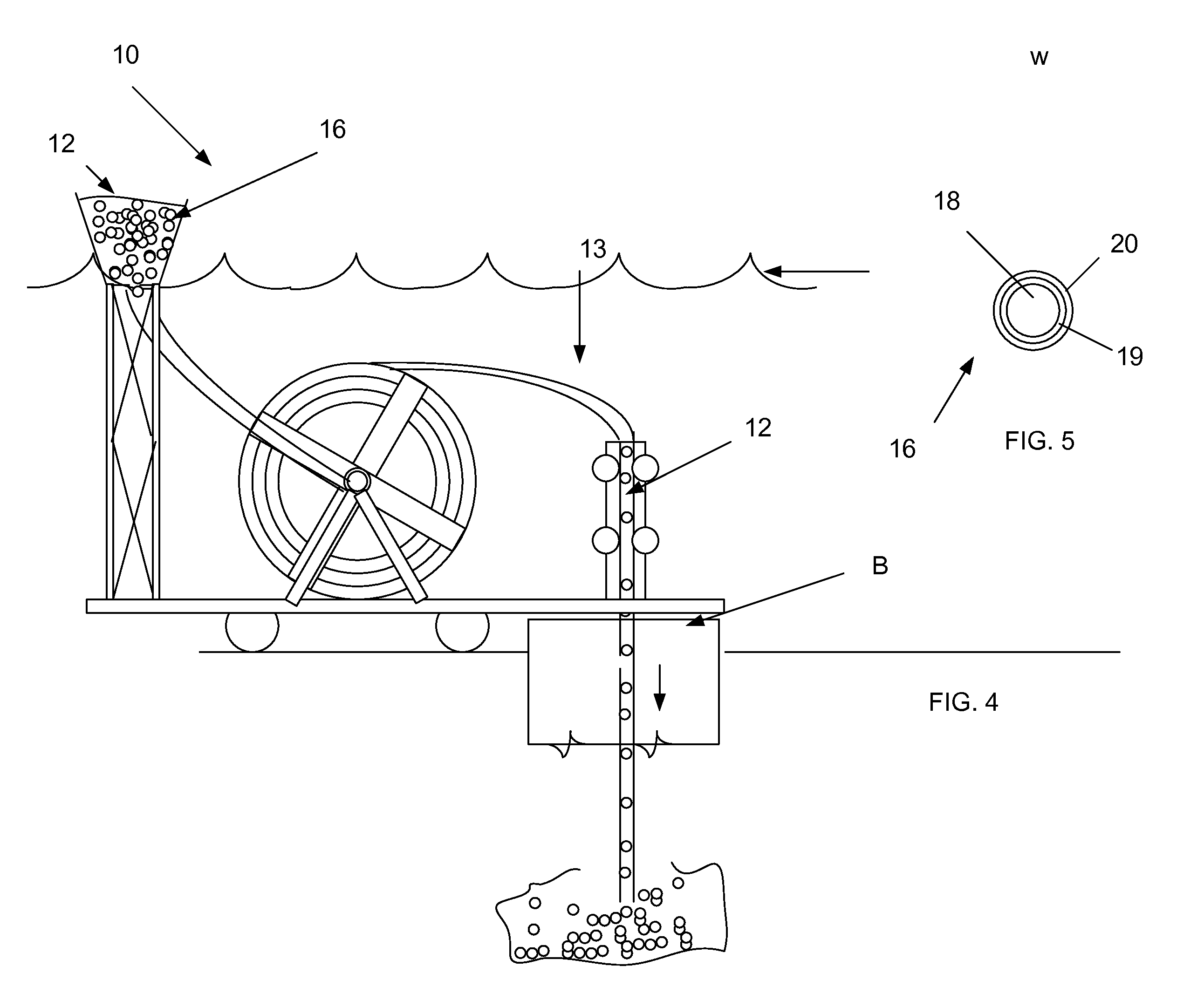
16. The method of claim 13, wherein said outer cover includes a dissolvable material.
17. The method of claim 13, wherein said plugging member includes an expanding polymer.
18. A system for plugging a well, which includes: a tank having a mud therein; a conduit connected to said tank; a pump operably connected to cause mud to flow through said conduit; a chamber operably connected to said conduit and including a top valve and a lower valve and wherein when said lower valve closed, said top valve can be open to filled said chamber with plugging members, and when said top valve is closed said lower valve can be opened to permit said plugging members to mix with said mud.
19. The system of claim 18, wherein said conduit is operably disposed to terminate adjacent said a perforation zone of the well.
Description
BACKGROUND OF INVENTION
[0001] 1. Field of Invention
[0002] The present invention relates in general to oil and gas well remediation. More particularly, the invention relates to compositions and method for use in plugging a well.
[0003] 2. Prior Art
[0004] In drilling a well, there is created a connection to the oil and/or gas reservoir and tubing is installed between the reservoir and the surface. The outer steel casing requires a gas tight seal between the reservoir and the surface wherein an annulus (the gap between the casing and the rock/formation) is typically subjected a cementing (or grouting) operation. This treatment is normally referred to as Primary Cementing. The main aspects of primary cementing are to isolate flow between different reservoirs, to withstand the external and internal pressures acting upon the well by offering structural reinforcement and to prevent corrosion of the steel casing by chemically aggressive reservoir fluids.
[0005] A poor cementing job can result in migration of reservoir fluids, even leading to gas migration through micro-annuli in the well which not only reduces the cost-effectiveness of the well but may cause a "blow out" resulting in considerable damage. Although repair jobs ("secondary cementing") are possible (in essence forcing more cement into the cracks and micro-annuli) they are costly and do not always lead to the desired results.
[0006] A "blowout" refers to the uncontrolled flow of well fluids from a well and "fluids" refer to both liquids and gases. Recently, offshore drilling operations have resulted in a major blow out.
[0007] Production tubing string includes a conduit in the well structure which contains petroleum fluids under pressure which, under conditions of a blowout, are uncontrollably escaping from some point along the vertical development of the conduit.
[0008] In such blow outs, oil leaks into rock formations outside the well. If the rock is porous, the oil would eventually bubble up from different spots in the ocean floor. It's important to know how high up in the well any breach or crack is. The higher it is, the worse the scenario because the closer it is to potentially porous rock and the ocean.
[0009] The well leak could be significantly worse than what's been measured from the end of the pipe. If you only measure the flow coming out of the end of the well bore, you're missing what is spurting from the break in the pipe. The clogging of the break is imperative in order to plug the well and minimize the ecological disaster.
[0010] In a small crack or break, a relatively small volume of cement (typically in the order of 100 m) is used to place the plug, its quality needs to be sufficient as it will serve as a seal for a very long time. However, in underwater operations, it is difficult to provide opposing fluid flow and plugging material.
[0011] The customary abandonment operation is very costly, especially in an off-shore environment, since it typically requires the use of a workover or drilling rig. It would be very beneficial if methods were available which could lead to abandonment of wells without the necessity to remove the production tubing.
[0012] One of the major drawbacks of using traditional cementing materials such as Class G Cement (e.g. OPC: Ordinary Portland Cement) in plugging is that such materials cannot achieve a gas tight seal. In the search for effective cementing materials, attention has to be paid to the material should be gas-tight (i.e. withstand a predetermined bar per m), it should have a controllable setting time so that a range of temperatures and well depths (each requiring different conditions) can be coped with, it should be thermally stable up to a predetermined temperature as well as being chemically stable against reservoir fluids for a very long period of time and its properties should be such that pumping through existing oil field equipment can be carried out without many problems.
[0013] A wide range of non-cement plugging agents have been attempted which include resins, golf balls, tire bits, for example. However, such materials have not met with great success. Compositions consisting essentially of a mixture of slurry of hydraulic cement (such as Portland cement) and rubber latex have been used. The use of putty ("mastic") has been disclosed for producing joints separating zones in wells.
[0014] Still others provide a method for controlling well blow outs, especially when those located in a body of water and the well cannot be conventionally controlled using drilling mud. The environmental hazards, as well as the hazards to personnel, of well blow outs have become increasingly important, especially where those blow outs have taken place in ecologically sensitive areas, such as the coast of the United States. None of the prior methods proves to be a universal application, and each poses some economic or technological drawback.
[0015] Some disclose methods and apparatus for producing deep boreholes in which the borehole is filled at least partially with a substance which remains in the liquid state and has a density greater than the mean density of the ground strata being drilled. Thus, any infiltrations from the formation into the borehole, as well as drilling debris, naturally move upward to the free surface of the liquid substance filling the borehole.
[0016] One prior method employs a so called "hot tap" which is a connection of a fluid-conducting conduit to a second conduit without the need for decreasing the pressure of the contents of the second conduit and without any substantial pressure loss or loss of the contents of the second conduit through the point of connection with the first conduit. U.S. Pat. No. 3,647,000 employs a method for capping the uncontrolled flow of oil and gas from petroleum wells located in a body of water. The method involves the tapping of a window or access opening into the well casing or tubing through which the well fluids are flowing below the surface of the well, crimping the casing or tubing above the point of the tap and injecting solid plugging bodies which lodge within the constriction in the production tubing string and form a plug blocking the flow. Heavy non-combustible mud is then pumped into the production tubing through the tapped-in access line until the weight of the injected mud overcomes the formation pressure, thus terminating well flow. Neither the nature of the plugging bodies nor the nature of the heavy mud is specified.
[0017] U.S. Pat. No. 3,926,256 discloses a method for preventing blow outs in offshore wells. There is an apparatus in which pins extend into the passage through which oil or gas are flowing, the uncontrolled flow being stopped by the injection into the pin-containing region of a sealer material such as balls of rubber or fiber, natural or synthetic, Fiberglas, aluminum, shredded Teflon, and the like, followed by a mastic which acts as the sealing agent.
[0018] U.S. Pat. No. 4,133,383 discloses a method for terminating formation fluid blow outs by introducing into the formation a low viscosity fluid which has the property of becoming highly viscous under the influence of heat.
[0019] It is also known to apply dry ice or liquid nitrogen to the exterior of the string through which the well is blowing out and thereby freeze the blowing fluids to form a plug in the string. In another development, the casing string through which the Ixtox I well in the Gulf of Mexico was blowing out during the summer of 1979 was treated with some success in an effort to cut down the flow by pumping in iron and lead balls.
[0020] A major problem with high pressure deep wells is that the mud and plugging components are not effective for various reasons. For example, the plugging components cannot descend to a depth necessary to perform their job in the face of the up-flow. Another problem is that the material breaks down prior to reaching the break or desired zone.
[0021] The present invention overcomes the above problems. The present invention provides for repair and abandonment operations in the face of high pressure deep wells.
SUMMARY OF INVENTION
[0022] It is an object to plug a well blow out.
[0023] It is another object to provide a composition for use in plugging a well.
[0024] Accordingly, the instant invention is directed to a composition and method for use in plugging a well. The invention provides a heavy metal, such as lead ball or other suitable geometric shape, which is covered by a highly resilient coating, such as steel, polymer, or ceramic, which can survive the sheer force as they fall against a fairly strong flowing stream so they can aggregate at the bottom of the well or pack into the break. Over time, a sufficient number of balls delivered would fill up over the perforations thereby plug the ability of the formations pressure to push production upward. Thus, this would stop the flow.
[0025] Such heavy metals and members can include those that can have the ability to expand and adhere to surfaces they come into contact with that can be used in conjunction with the balls either as a coating or embedded into them. Further, the plugging composition can be equipped with ability to become more stable once they arrive at the break or bottom of the wellbore. Preferred geometric designs can include round and or cone shaped as a method to reduce the drag or tendency of the flow to lift is a very important feature as well. In the instant invention, a hopper with a valve can open to deliver the composition which connected downstream of a pump to the pipe going into the wellbore. The composition drilling mud can be pumped and the drilling mud will carry these plugging members (e.g., balls) and keep them suspended in the thick fluid. The composition is configured as a mechanism to deliver these balls to the site with sufficient ability to permit the balls to descend downward. The size and shape and make-up of the balls and carrier mud fluid are factors which provide necessary blocking or plugging effect.
[0026] With a direct line "unobstructed" open hole into a well, a string of coil tubing or small diameter conventional tubing can be injected into the existing tubing or open wellbore in a sight line. Optionally, the use of a blowout preventer can be employed to carry out delivery. The small string tubing would be used to pump down the plugging members (balls or cones) into the well near the bottom. A method can be provided to deliver of the plugging members into a hopper that is connected to the coil tubing just below the mud pump whereby these balls or comes would be injected into the stream of mud being pumped down.
BRIEF DESCRIPTION OF THE DRAWINGS
[0027] FIG. 1 is an elevation partially broken away of an exemplary well installation employed in wells located in water;
[0028] FIG. 2 is a partial elevation partially broken away illustrating a portion of the well structure of FIG. 1 and the implementation of one embodiment the invention;
[0029] FIG. 3 illustrates a plugging element of one embodiment of the invention;
[0030] FIG. 4 is a partial elevation partially broken away illustrating a portion of the well structure of FIG. 1 and the implementation of another embodiment the invention;
[0031] FIG. 5 illustrates a plugging element of another embodiment of the invention; and
[0032] FIG. 6 is a schematic illustrating an embodiment of the invention.
DESCRIPTION OF THE PREFERRED EMBODIMENT
[0033] Referring now to the drawings, the composition and method of present invention is generally designated by the numeral 10 and is for use with deep high pressure wells located in water. It will be understood however, that the present invention can be employed with wells located on land.
[0034] A typical well structure is designated by the numeral 4 is illustrated within a body of water indicated generally at W. The well structure 4 extends above the top of the surface of the water W and normally terminates at a well head (not shown) which includes regulating and control equipment and fittings for conducting the well fluids to a collection point.
[0035] The structure 4 includes an external conductor pipe 30 which extends from above the surface of the water W to a point somewhat below the surface of the water bed indicated generally at S. Typical intermediate casing string 32 and a producing casing string 34 are carried concentrically within the conductor pipe 30 and extend to different subterranean points within the well bore. Concrete 36 is illustrated within the annular space between the conductor pipe 30 and intermediate casing string 32. A production tubing string 38 extends through the center of the well structure 4 and is normally the principle conductor employed for conveying the petroleum fluids from the subterranean formation to the wellhead. Under normal conditions, with a well structure such as illustrated in FIG. 1, petroleum fluids in the formation are conducted through the production tubing string 38. The intermediate and production casing strings 32 and 34 normally contain little or no pressure and effluent flow is limited to the production tubing string 38.
[0036] Pressure estimates for deep offshore wells range from 3500 psi to 9500+ps or from 20 MPa to 65 MPa. It is not uncommon for the well bore diameter to be large for example a foot in diameter. A blowout requires immediate remediation.
[0037] Plugging the hole can include the use of coiled tubing 13 wherein coiled tubing is run into the hole and pumping the composition 12 with plugging members 16 enable killing fluid flow. Coiled tubing can be a conventional continuous length of low-alloy carbon-steel tubing that can be spooled on a reel and deployed into a wellbore B for delivering composition 12. One method is to inject the tubing 13 to near the perforations P. However, if this cannot be achieved due to debris in the wellbore B, the tubing 13 can be injected to a depth where it is possible and by creating a large flow of mud 15 with plugging members 16, the well flow will be reduced allowing the plugging members 16 to fall from such point to the bottom of the well.
[0038] Optionally, a blowout preventer 14 which includes a manifold communicably connected to receive the composition 12 which includes plugging members 16 of the instant invention can be provided. The composition 12 includes noncombustible high-density well control material or "mud" 15 and the plugging members 16, As seen in section in FIGS. 3 and 5, the plugging members 16 can include a core 18, such as heavy metal with one or more coating 19 and 20 which can be a friction reduced and or durable coating, such as a polymer, steel, or ceramic coating.
Sample Density of materials are as follows:
TABLE-US-00001 metal g/cm{circumflex over ( )}3 lb/in{circumflex over ( )}3 lb/ft{circumflex over ( )}3 lb/gal water 1.00 0.036 62 8.35 aluminum 2.70 0.098 169 22.53 zinc 7.13 0.258 445 59.50 iron 7.87 0.284 491 65.68 copper 8.96 0.324 559 74.78 silver 10.49 0.379 655 87.54 lead 11.36 0.410 709 94.80 mercury 13.55 0.490 846 113.08 gold 19.32 0.698 1206 161.23
[0039] Some material is cost prohibitive in addition to being malleable while others are less costly, yet malleable and toxic such as lead and mercury. In order to use these materials, the material is to be coated with a sufficient coating to permit use under the rough forces within the well bore, i.e., be pushed down by the drilling fluids using pump 17, e.g., 20,000 hp.
[0040] To this end, a sufficiently sized plugging member 16 can be formed of lead for example and then coated with a suitable coating. One coating for use with the invention can include Molybdenum Disulfide (MoS2) combined with one of nylon (with the trade name Nylatron), Teflon, and Vespel. Another self-lubricating composite coating for high-temperature application includes molybdenum disulfide and titanium nitride formed by chemical vapor deposition. Other silicon based ceramics including silicon nitride and silicon carbide can be used their high temperature strength and relative corrosion resistance.
[0041] The concept is to provide a sufficient resistant force with the blowout preventer to permit the coated pellets to drop to the well blocking point. The coating 19 and/or 20 permits the normally mechanically weak, but heavy material to survive a mile long journey under very high pressure in 1200 gpm within a rigid pipe. The coating 19 or 20 can be a drag reducing material such as a hydrophobic coating, such as Wearlon Super F-6M.TM. available from Industrial Coating Systems in China. It is also contemplated that one of the coating 19 or 20 can include a well treating agent. Optionally the coating 19 or 20 can include a dissolvable material, such as a soluble polymer, which can house the heavy substance or adhesive substance such that once reaching the bottom of the well or perforation P, it can dissolve and permit the heavy material to block the perforation P. Still another option is to provide coating with water-activated urethanes which expand, i.e., as water absorbs into the urethane polymers.
[0042] As generally seen in FIG. 6, it is envisioned that a mud 15 can be pumped via a pump 17 using coiled tubing 13. The mud 15 can include drilling fluids can be water-based muds (which can be dispersed and non-dispersed), non-aqueous muds, usually called oil-based mud, and gaseous drilling fluid, in which a wide range of gases can be used or synthetic mud.
[0043] Intersecting the tubing 13 is a chamber 29 which includes a top valve 21A and a lower valve 21 B. With valve 21B closed, Valve 21A is open to fill the chamber 29. Then with valve 21A closed, valve 21B can be open to permit the plugging members 16 to mix with the mud 15. The plugging members 16 can preferably be formed in a variety of sizes to permit restrictions to form and plugging of the well.
[0044] Formation F pushes into well at perforations P where production is coming into well bore B. The plugging members 16 by virtue of their weight and coating structure are enabled to flow to a point whereby they can form a restriction in the well, i.e., enable them to fall into the bottom of the well adjacent the perforation P and can aid in blocking the flow.
[0045] In another aspect of the present invention, upon occurrence of a blowout, blowout preventer 14 can be operably disposed over well bore B. In most wells located in bodies of water in the ocean or in waters such as the Gulf of Mexico, the vertical distance between the water surface and the bed S provides ample working room and overhead protection.
[0046] Referring to FIG. 2, once so positioned, the blowout preventer 14 is actuated to cause the flow of mud composition 12 which includes plugging members 16 which by virtue of their weight and coating structure are enabled to flow to a point whereby they can form a restriction in the well. These plugging members 16 migrate through a fluid current to form the restriction.
[0047] When the plug P has terminated or substantially terminated, conventional mud can then introduced into the tubing string 38 at a pressure which is sufficient to overcome the formation pressure and displace the petroleum fluids from the production tubing string 38. The mud 15 flows down hole into the production string 38 until the weight of the inserted mud is sufficient to overcome the formation pressure. Thereafter, the well bore B may be closed and the well may be abandoned or repaired as desired.
[0048] It will be appreciated that the method of the present invention encompasses the steps of inserting plugging materials of the instant invention into a conduit at a point whereby there is a sufficient opposing current created to permit the free fall of the plugging members 16 causing a plug to form internally of the conduit or at the formation zone F. The particular apparatus employed in forming the restriction or in forming the upstream access point for introduction of plugging materials is conventional and improved equipment and techniques for effecting these steps is anticipated and may form the subject matter of future patent applications.
[0049] It will be understood that other suitable means may be employed for supplying the plugging members 16 and mud composition 12. If desired, however, other suitable subsurface equipment may be employed for the same purpose.
[0050] The plugging members 16 are denser than the petroleum effluents. It will be understood, that the method of the present invention is readily capable of use with plugging members 16 of a suitable density provided with a coating 19 and or 20 which is preferably non-toxic and able to withstand the rigors of the harsh well environment. The flow of composition 12 must be strong enough to permit the plugging members 16 to reach the desired zone or break point.
[0051] The foregoing disclosure and description of the invention is illustrative and explanatory thereof and various changes in the procedures as well as in the details of the described method may be made within the scope of the appended claims without departing from the spirit of the invention.
* * * * *
D00000
D00001
D00002
D00003
D00004
XML
uspto.report is an independent third-party trademark research tool that is not affiliated, endorsed, or sponsored by the United States Patent and Trademark Office (USPTO) or any other governmental organization. The information provided by uspto.report is based on publicly available data at the time of writing and is intended for informational purposes only.
While we strive to provide accurate and up-to-date information, we do not guarantee the accuracy, completeness, reliability, or suitability of the information displayed on this site. The use of this site is at your own risk. Any reliance you place on such information is therefore strictly at your own risk.
All official trademark data, including owner information, should be verified by visiting the official USPTO website at www.uspto.gov. This site is not intended to replace professional legal advice and should not be used as a substitute for consulting with a legal professional who is knowledgeable about trademark law.