Producing Hydrocarbon Material From A Layer Of Oil Sand
BEST; Bruno
U.S. patent application number 13/166475 was filed with the patent office on 2011-12-29 for producing hydrocarbon material from a layer of oil sand. This patent application is currently assigned to SHELL OIL COMPANY. Invention is credited to Bruno BEST.
| Application Number | 20110315379 13/166475 |
| Document ID | / |
| Family ID | 42558492 |
| Filed Date | 2011-12-29 |


| United States Patent Application | 20110315379 |
| Kind Code | A1 |
| BEST; Bruno | December 29, 2011 |
PRODUCING HYDROCARBON MATERIAL FROM A LAYER OF OIL SAND
Abstract
A method of producing hydrocarbon material from a layer of oil sand in an earth formation, the layer having a thickness and extending in an extension direction for more than its thickness, the method comprising: an injection borehole having an injection borehole section extending in an injection borehole direction and a discharge borehole having a discharge borehole section extending in a discharge borehole direction below the injection borehole section, wherein both the injection and the discharge borehole directions deviate less than 45 degrees from the extension direction; creating a cavity in the layer, the cavity being in fluid communication with both the injection and the discharge borehole sections; extending the cavity by operating fluid jetting means via the injection borehole against a wall of the cavity to obtain a slurry; and withdrawing the slurry from the cavity via the discharge borehole to a processing facility.
| Inventors: | BEST; Bruno; (Rijswijk, NL) |
| Assignee: | SHELL OIL COMPANY Houston TX |
| Family ID: | 42558492 |
| Appl. No.: | 13/166475 |
| Filed: | June 22, 2011 |
| Current U.S. Class: | 166/275 |
| Current CPC Class: | E21F 15/08 20130101; E21B 43/29 20130101; E21B 43/305 20130101; E21C 41/24 20130101 |
| Class at Publication: | 166/275 |
| International Class: | E21B 43/16 20060101 E21B043/16 |
Foreign Application Data
| Date | Code | Application Number |
|---|---|---|
| Jun 24, 2010 | EP | 10167158.4 |
Claims
1. A method of producing hydrocarbon material from a layer of oil sand located in an earth formation, the layer of oil sand having a thickness and extending in an extension direction for more than its thickness, the method comprising: a) creating a borehole arrangement in the earth formation, including an injection borehole having an injection borehole section extending in an injection borehole direction, and a discharge borehole having a discharge borehole section extending in a discharge borehole direction below the injection borehole section, wherein both the injection and the discharge borehole directions are deviating less than 45 degrees from the extension direction; b) creating a cavity in the layer of oil sand, the cavity being in fluid communication with both the injection and the discharge borehole sections; c) extending the cavity by operating fluid jetting means via the injection borehole to jet a stream of fluid against a wall of the cavity, to obtain a slurry comprising fluid, hydrocarbon material, and sand; and d) withdrawing the slurry from the cavity via the discharge borehole to a processing facility for processing the slurry.
2. The method according to claim 1 wherein the pressure in the cavity, while the fluid jetting means is operated, is lower than the pressure in the pristine oil sand layer before creating the cavity therein.
3. The method of claim 1 wherein fluid is also injected into the cavity via the discharge borehole.
4. The method of claim 1 wherein no injection or discharge borehole in fluid communication with the cavity is arranged, which borehole is a vertical or near-vertical borehole.
5. The method of claim 1 wherein both the discharge borehole and the injection borehole are provided with a tubular of a length adapted to be changed, and wherein the lengths of both tubulars are changed in correspondence with the extension of the cavity.
6. The method of claim 5 wherein changing the length of at least one of the tubulars comprises operating a shortening device, in particular wherein the tubular is made of a non-metal, such as a plastics material.
7. The method of claim 1 wherein the discharge borehole is provided with a pump for pumping the slurry via the discharge borehole to the processing facility and wherein the pump is sealed relative to an inner surface of the liner.
8. The method of claim 7 wherein the pump is axially movable through the discharge borehole, and wherein the method further comprises axially moving the pump through the discharge borehole in correspondence with changing the length of the liner.
9. The method of claim 1 wherein the pump is driven by a stream of fluid pumped through a conduit extending through the discharge borehole, preferably, wherein at least a portion of said stream of fluid is injected into the slurry of fluid and oil sand present in the cavity.
10. The method of claim 1 wherein at least one of the injection borehole section and the discharge borehole section extends substantially horizontal.
11. The method of claim 1 wherein the method further comprises inserting refill material into the cavity.
12. The method of claim 11 wherein the refill material is transported from the processing facility to the cavity.
13. The method of claim 11 wherein the borehole arrangement in the earth formation includes a refill borehole having a refill borehole section extending in a refill borehole direction deviating less than 45 degrees from the extension direction.
14. The method of claim 11 wherein the refill borehole section is arranged below the discharge borehole section.
15. The method of claim 11 wherein inserting refill material into the cavity comprises providing a refill borehole having a refill borehole section extending in a refill borehole direction deviating less than 45 degrees from the extension direction, the refill borehole section being provided with a casing; after extending the cavity for a selected length, perforating the casing within that length, and pumping refill material from the refill well through the perforations.
Description
[0001] This application claims the benefit of European Application No. 10167158.4 filed Jun. 24, 2010 which is incorporated herein by reference.
TECHNICAL FIELD OF THE INVENTION
[0002] The present invention relates to a method of producing hydrocarbon material from a layer of oil sand located in an earth formation.
BACKGROUND OF THE INVENTION
[0003] In the industry of hydrocarbon production from subterranean reservoirs, it is conventional practice that oil or gas is produced from wellbores by virtue of the high fluid pressures existing downhole. In case of high viscosity oil, downhole pumps can be applied to pump the oil to surface, or other methods can be applied to increase the oil production rate such as steam injection or CO2 injection into the formation. However, the conventional methods are not adequate for the production of heavy hydrocarbon material present in rock formations, when the material is not flowing up a well. Examples are bituminous oil or tar or kerogen occurring in sands, standstone, or shale based reservoirs in Canada or elsewhere, e.g. tar sands or Limestone/Dolomite based and calcareous shale based reservoirs such as found in the Canadian Athabasca or Grosmont regions. Such a reservoir will herein be referred to as oil sand. Hydrocarbons from oil sand layers can in principle be recovered by mining. As some oil sands layers occur at relatively shallow depths, typically between 0 to 200 meters, it is common practice to produce oil from these layers by surface mining whereby the overburden layer is removed using draglines and/or shovels and trucks. The produced oil sand is transported to one or more processing facilities for separation of hydrocarbon fluid from the sand slurries. However, for oil sands layers at greater depths, removal of the overburden is costly and has a significant impact on the environment. Therefore alternative methods for producing oil sands have been proposed.
[0004] One such alternative method is disclosed in a technical paper published in CIM magazine by the Canadian Institute of Mining & Metallurgy, 2001, Vol. 94, Nr. 1054, pages 63-66, entitled "Hydraulic underground mining of oil sands--the next big step", by D. D. Tannant et al. This publication discloses a method of producing hydrocarbon fluid from an oil sands layer located in an earth formation, wherein a first horizontal borehole is drilled into the oil sands layer and a fluid jetting device is operated through the borehole to excavate the oil sands layer and thereby form a cavity in the oil sands layer. A slurry of fluid and oil sands is formed in the cavity as a result of the fluid jetting operation. Slurry is withdrawn through the borehole, and a stable cavern is formed containing caved oil sands, water, and possibly injected air. The cavern is used as a primary fractionator, in which bitumen rises to the top and sand sinks to the bottom. A second horizontal borehole is provided above the first borehole, to an upper part of the cavity, to withdraw water and oil. Once the bitumen is removed, thickened tailings recovered from the portion of the oil sands slurry that was sent to surface for processing are placed back via the second borehole in the upper part of the cavern.
[0005] Another method is disclosed in WO 2008/064305, in which horizontal boreholes extending from a main access tunnel are used to recover oil sands. FIG. 6 of this publication discloses two horizontal boreholes, one above the other. The lower borehole is a production well, through which a hydraulic mining bit is operated to create a mined volume that enlarges upwardly, until it reaches the level of an upper sand injection well, at which point mining is stopped and sand is injected from the upper well. Initially the sand injection well can also be used to create a small mined volume at its toe, above and separate from the mined volume at the toe of the production well. The upper mined volume can then be filled with sand slurry and pressurized, to assist the hydraulic mining process being applied from below. In a variant of the known method the lower production and upper sand slurry injection well can also be operated simultaneously, wherein the sand slurry injection well sticks out into the cavity and sprays a stream of tailings slurry into the cavity.
[0006] International patent publications No. WO 2010/000729 and WO 2010/000736 disclose methods of producing hydrocarbon fluid from a layer of oil sand, wherein a plurality of vertical injection/refill boreholes and a discharge borehole having a substantially horizontal borehole section are operated.
[0007] However, there is still a need for an improved method of producing hydrocarbon material from an oil sands layer.
SUMMARY OF THE INVENTION
[0008] In accordance with the invention there is provided a method of producing hydrocarbon material from a layer of oil sands located in an earth formation, the layer of oil sands having a thickness and extending in an extension direction for more than its thickness, the method comprising: [0009] creating a borehole arrangement in the earth formation, including an injection borehole having an injection borehole section extending in an injection borehole direction, and a discharge borehole having a discharge borehole section extending in a discharge borehole direction below the injection borehole direction, wherein both the injection and the discharge borehole directions are deviating less than 45 degrees from the extension direction; [0010] creating a cavity in the layer of oil sands, the cavity being in fluid communication with both the injection and the discharge borehole sections; [0011] extending the cavity in the extension direction by operating fluid jetting means via the injection borehole to jet a stream of fluid against a wall of the cavity, to obtain a slurry comprising fluid, hydrocarbon material, and sands; and [0012] transporting the slurry from the cavity via the discharge borehole to a processing facility for processing the slurry.
[0013] In this manner, hydrocarbon-containing slurry that is formed in a lower part of the cavity by the erosive action of the fluid jetting means and under the influence of gravity, can be effectively removed via the discharge borehole arranged below the fluid injection borehole, i.e. in a lower part of the cavity.
[0014] Preferably pressure in the cavity, while the fluid jetting means is operated, is lower than the bubble point pressure in the pristine oil sands layer before the cavity is created therein, in particular 50% or less of the pristine pressure, more in particular 20% or less. Oil sands layers can have gas present, e.g. methane. The gas can e.g. be adsorbed or dissolved. Lowering the pressure below the pressure at which gas can be released from pores in the sand matrix (which pressure is referred to as bubble point pressure) can lead to damage to the sand matrix, and to the loss of strength of the oil sands, at the walls of the cavity. Removal of material by a hydraulic jet becomes much easier, and the disintegrated oil sand will sink to the bottom of the cavity.
[0015] In one embodiment, fluid is also injected into the cavity via the discharge borehole. A particular purpose of this is for stirring or mobilizing the slurry and breaking of any larger lumps of material in the area of the cavity from which the slurry is withdrawn via the discharge borehole.
[0016] In one embodiment, no injection or discharge borehole in fluid communication with the cavity is operated, which borehole is a vertical or near-vertical borehole. Near-vertical means that the average angle between the vertical and the borehole from surface to cavity is less than 45 degrees. The present invention allows to excavate a layer of oil sands using deviated boreholes, with horizontal or near-horizontal borehole sections in the oil sands layer for extended distances, and thus without the need for a multitude of vertical or near-vertical wells.
[0017] Suitably the discharge borehole is provided with a liner of a length adapted to be changed, and the injection borehole is provided with injection tubular of a length adapted to be changed, and wherein both the lengths of the liner and of the injection tubular are changed in correspondence with the extension of the cavity. The tubular can for example be a fluid injection tubular or a liner.
[0018] The length of such a tubular can be changed by a shortening device. For example, the step of shortening the liner can comprise operating a cutting device to cut the liner. The liner can also be shortened by the action of a fluid jet, or by any other means, e.g. by milling, explosives, or a laser. Shortening can be done by removing coarse discrete pieces of the liner, such as at suitable time intervals, or by producing small chips of the liner material. To this end the liner is suitably made from a suitable material for shortening. The liner can be made of metals softer than steel, e.g. aluminium. Preferably the liner is made of a non-metal material, and in particular the liner can be made of a plastics material, such as a material comprising 50 wt % or more of a polymer.
[0019] In one embodiment the discharge borehole is provided with a pump for pumping the slurry via the discharge borehole to the processing facility, preferably the pump is sealed relative to an inner surface of the liner. The pump can be axially movable through the discharge borehole, and moved in correspondence with changing the length of the liner. The pump can e.g. be driven by electricity, but also by a stream of fluid pumped through a conduit extending through the discharge borehole. In the latter case, at least a portion of said stream of fluid is suitably injected into the slurry of fluid and oil sands present in the cavity, e.g. for stirring.
[0020] The method can further comprise inserting a stream of refill material into the cavity. The stream of refill material can comprise tailings that are separated in and transported from the processing facility to the cavity.
[0021] In one embodiment a refill borehole having a refill borehole section extending in a refill borehole direction deviating less than 45 degrees from the extension direction is provided. Preferably the refill borehole section is arranged below the discharge borehole section, in particular near or at the lower end of the cavity or just below, e.g. 0-10 m below. There it is nearly unaffected by a (partial) collapse of the cavity. Refill material can be pumped with excess pressure in to the cavity in a controlled way from below.
[0022] In a preferred option inserting a stream of refill material into the cavity comprises providing the refill borehole section with a casing. The casing protects against collapse of the borehole. After extending the cavity for a selected length, the casing is perforated within that length, and refill material is pumped through the perforations.
BRIEF DESCRIPTION OF THE DRAWINGS
[0023] The invention will be described hereinafter in more detail, and by way of example, with reference to the accompanying drawings in which:
[0024] FIG. 1 schematically shows an example of a production unit for use in an embodiment of the method of the invention;
[0025] FIG. 2 schematically shows a detail of the production unit of FIG. 1;
[0026] FIG. 3 schematically shows another example of a production unit for use in an embodiment of the method of the invention; and
[0027] FIG. 4 schematically shows a top view at surface of a production field using embodiments of the present invention.
[0028] In the Figures, like reference numerals relate to like or similar components.
DETAILED DESCRIPTION OF THE PREFERRED EMBODIMENTS
[0029] Referring to FIGS. 1 and 2 there is shown an earth formation 1 containing an oil sands layer 2 located between an overburden layer 4 above the oil sands layer 2 and an underburden layer, shown as a layer of rock material 6, such as limestone, below the oil sands layer 2. Earth formation below the oil sands layer is referred to as underburden. The oil sands layer 2 has respective upper and lower boundaries 20, 22 extending generally horizontally in this example. An overburden can for example be between 50 and 1000 m thick, in particular between 100 and 800 m. The layer of oil sands extends in an extension direction 21, in particular a non-vertical extension direction, in this example horizontally between an overburden and an underburden. The layer of oil sands has a thickness defining a thickness direction 21a, which is in this example vertical. The extension direction 21 is different from, often perpendicular to, the thickness direction, and is in this example in the horizontal plane. The layer extends more in the extension direction than its thickness, typically for more than twice its thickness, such as for more that 5 or 10 times its thickness, or even more. It will typically extend for less than 10000 times its thickness.
[0030] The thickness can for example be between 1 m and 500 m, in particular between 5 m and 200 m, such as between 10 and 100 m, and may vary along the extension direction. It will be understood that the layer can extend along a flat or curved plane.
[0031] An injection borehole 8 is provided which in this example is a deviated borehole extending from an injection station 10 at the earth surface 11 to a cavity 12 formed in the layer of oil sands 2. The cavity has an upper portion 12a containing gas (e.g. CO2, methane, air, and/or H2S) and a lower portion 12b containing a mixture (referred to hereinafter as "slurry") 13 of fluid (preferably water) and oil sands particles comprising hydrocarbon material and sand, which may partly or fully separate in the slurry.
[0032] A deviated discharge borehole 14 extends from a production station 15 at the earth surface to the cavity 12 whereby the production station 15 is horizontally spaced from the injection station 10 and debouches into the lower cavity portion 12b at some distance above the bottom of the cavity.
[0033] The injection borehole 8 and the discharge borehole 14 each have an upper section 16, 16a extending downwardly, such as substantially vertically from surface, and a non-vertical lower section 18, 18a. The expression lower borehole section is used for a borehole section that is further away from surface along the borehole trajectory than an upper borehole section. The lower borehole section 18 of the discharge borehole extends in a discharge borehole direction, below the injection borehole section 18a of the injection borehole 8, extending in an injection borehole direction. Each of the injection and discharge borehole directions is a selected direction within the layer 2, in this example an azimuthal direction from the cavity 12. The intersection between the lower borehole section 18a of the injection borehole 8 and the cavity 12 defines a front surface 23 of the cavity 12.
[0034] Each of these selected directions suitably is a direction within the layer. The lower sections of the injection and discharge boreholes each deviate less than 45 degrees from the extension direction 21, wherein the angle is preferably counted in a vertical plane through the extension direction. These borehole sections preferably extend substantially parallel to the upper boundary 20 and/or lower boundary 22 of the oil sands layer 2. Suitably the selected direction substantially coincides with the extension direction, so that the cavity is extended within the layer, substantially parallel with its upper and/or lower boundary, for more than the layer thickness, such as for between 2 and 5000 times the layer thickness. The expression "substantially parallel" herein accounts for the precision with which deviated boreholes can be drilled in an underground layer. In the present example the lower sections 18, 18a extend substantially horizontally. The expression "direction" is used herein to refer to a direction without specifying the sense of direction, unless otherwise indicated. The extension direction may deviate somewhat from the horizontal plane due to geological circumstances, as can the directions of the lower sections 18, 18a in the practice of directional drilling. It is desired to arrange the lower sections such that they extend for a substantial length within the oil sands layer, such as for between 50 and 5000 m, in particular between 100 and 2000 m. The injection and discharge borehole sections preferably deviate less than 30 degrees from the extension direction, more preferably less than 15 degrees. It can alternatively be said that the injection and discharge borehole sections preferably are substantially horizontal borehole sections. A substantially horizontal borehole section deviates 30 degrees or less from the horizontal plane, more preferably 15 degrees or less. The selected direction can be at least 45 degrees away from the thickness direction, in particular at least 45 degrees away from the vertical. All angles specified herein are to be understood as absolute (positive) values, unless otherwise specified. It will be understood that when the cavity is extended along the injection and/or discharge borehole directions that deviate by a certain angle from the extension direction, the cavity is at the same time extended in the extension direction.
[0035] The expression "extending below" in relation to two borehole sections is used to refer to the situation that one borehole section extends at a greater vertical depth than the other. Preferably the two borehole sections extend substantially along the same trajectory in a vertical projection onto the earth's surface, which can for example mean that the horizontal deviation in such projection is 50 m or less, preferably 10 m or less, more preferably 5 m or less, such as 2 m or less.
[0036] The vertical distance between the discharge borehole section and the injection borehole section thereabove is suitably in the range of 1-100 m, preferably between 2 and 50 m, such as between 5 and 30 m.
[0037] The upper borehole sections 16, 16a are each provided with a conventional casing (or liner) 24, 24a, whereas the lower borehole sections 18, 18a are each provided with a liner 26,26a, e.g. of plastics material, for example glass fibre reinforced plastic. The liner 26 extends a minimal distance into the cavity 12. Furthermore in this example, a jet pump 28 is positioned in the liner 26 in a manner that the jet pump 28 is sealed relative to the inner surface of the liner 26 and is axially movable through liner 26. A fluid conduit 30 for driving the jet pump 28 extends from the production station 15 through the casing 24 and the liner 26 to the jet pump 28. When driven by fluid, such as water, pumped through the fluid conduit 30, the jet pump 28 is arranged to pump the slurry 13 of fluid and particles from the lower cavity portion 12b, via the annular space between the fluid conduit 30 on one hand and the liner 26 and casing 24 on the other hand, to the production station 15. The jet pump 28 is thereto provided with one or more flow channels 32 (FIG. 2) allowing the slurry to flow in axial direction through the jet pump 28. The fluid conduit 30 extends further from the jet pump 28 through liner 26 to the cavity 12. A lower end part 34 of the fluid conduit 30 is provided with a shortening device, in this embodiment cutter 36, for shortening the liner 26, one or more nozzles 38 for initially forming the cavity 12 and/or for stirring the slurry present in the cavity 12, and a bit or mill 39 for crushing lumps of rock material that may be present in the cavity 12. Conduit 30 can be rotatable.
[0038] Alternatively, the discharge borehole can also be set up for operation in `reverse circulation`, where driving fluid for the jet pump is pumped from surface via the annulus, and slurry is pumped via an inner tubular like reference numeral 30. Liner 26 and jet-pump 28 are suitably designed to withstand the pressure of driving fluid, e.g. a plastic liner of sufficient strength can be used. An advantage of this reverse circulation operation is that there is no wear of the slurry in the annulus. Also the slurry travelling inside a slowly rotating production pipe will not be able to settle down. An injection string 40 for injecting fluid into the cavity 12 extends from the injection station 10 via the injection borehole 8 into the cavity 12, the injection string 40 having a lower end provided with fluid jetting means in the form of fluid jetting head 41 comprising jetting nozzles 42, the fluid jetting head being located in the upper portion 12a of cavity 12. An annular seal 43 (e.g. such as used in a rotating head) is arranged in an upper part of the first injection borehole 8 to seal the annular space formed between the injection string 40 and the wall or casing of the first injection borehole 8. The injection string 40 can also be provided with a shortening device (not shown) for shortening the liner 26a extending into the cavity 12, which can be similar to the shortening device 36 of the conduit 30.
[0039] Injection string 40 can be rotatable.
[0040] In this embodiment there is further provided a refill borehole 108 which in this example is also a deviated borehole extending from a refill station 110 at the earth's surface 11 to the lower end of the cavity 12. The refill borehole 108 has an upper section 116 extending downwardly, such as substantially vertically, and a lower section 118. The lower borehole section 118 extends below lower non-vertical section 116 of the discharge borehole 14, such as between 1 and 20 m below the lower section in particular between 2 and 10 m, preferably substantially parallel therewith. The lower borehole section preferably extends substantially along the lower boundary 22, such as within 5 meters from the boundary, preferably within 1 m from the boundary. The refill borehole 108 on this embodiment is provided with casing 124, preferably a steel casing, and with an injection string 148 for refill material, which can be rotatable. The injection string is optional; the injection borehole could alternatively be arranged without such string, so that the injection slurry is passed through the casing. The refill borehole section preferably deviates less than 30 degrees from the extension direction, more preferably less than 15 degrees. It can alternatively be said that the refill borehole section preferably is a substantially horizontal borehole section.
[0041] FIG. 1 shows the invention with several of the components at a stage of normal operation after some time of operation. The cavity 12 is being extended by operating the fluid jetting means using nozzles 42 via the injection borehole to jet a stream of fluid against a wall of the cavity, in particular the front surface 23, starting from an initial cavity 12' in an azimuthal direction, along the parallel lower borehole sections 18 and 18a. The initial cavity 12' that was created in the layer of oil sands 2 is indicated with a dashed line. Suitably the jetting fluid is a low solids fluid, i.e. it contains substantially no solids, such as less than 10 wt % or less than 1 wt % of solids. Water is a suitable jetting fluid. The water can contain one or more additives such as a surfactant, but this is not required. Reference to water herein is to a fluid that contains at least 80 wt %, preferably at least 90 wt % of pure water. The temperature of the jetting fluid (water) can be selected or modified such as by heating. For example, water at a temperature of 25.degree. C. or above, or 40.degree. C. or above, can be used.
[0042] Thus the front surface 23 of the cavity has been moving in the extension direction, with the sense of direction generally uphole, defined by the injection borehole's sense of direction towards surface. As a result, the lower borehole sections 18, 18a have become shorter compared to an initial length indicated at 18' and 18a'. The liners 26 and 26a have been shortened at the side of the cavity 12 in correspondence with shortening of the lower borehole sections 18,18a. The fluid conduit 30 with the jet pump 28 connected thereto has been pulled upward through discharge borehole 14 over a distance about equal to the reduction in length of liner 26, and likewise the injection string 40 has been retracted, so that the nozzles stay in sufficient proximity to the front wall 23 so that the fluid jetting is effective to extend the cavity. Suitably, the nozzles are at a distance of between 0.5 m and 15 m from the wall against which the fluid jet is exerted.
[0043] During normal operation of the system of FIGS. 1-2, the injection borehole 8 and the discharge borehole 14, and preferably the refill borehole that will be discussed later, are drilled into the oil sands layer 2 using one or more conventional drilling rigs, and completed as needed, such as with the casings 24, 24a and liners 26,26a. The injection station 10 and the production station 15 are installed at their respective positions as indicated in FIG. 1. In a next step, the initial cavity is created. The fluid conduit 30 with the jet pump 28 connected thereto is lowered through the discharge borehole 14 until end part 34 of the fluid conduit 30 extends just beyond the far end of the liner 26. Water at high pressure is then pumped from the production station 15 into the fluid conduit 30 so that the pumped water is jetted through the nozzles 38 to impact the formation at the end of the liner 26 with great force. Alternatively, the discharge borehole is operated in reverse circulation as discussed above. If desired, the fluid conduit 30 is simultaneously rotated about its longitudinal axis to induce the bit or mill 39 to crush the rock formation. As a result the oil sands layer 2 is gradually excavated so that the cavity 12' and the slurry 13 of water and oil sand particles are initially formed. Furthermore, by virtue of pumping of water through fluid conduit 30, the jet pump 28 is operated to pump the slurry 13 from the cavity 12' via the flow channels 32 of the jet pump 28 and via the annular space 27 between the fluid conduit 30 and the liner 26/casing 24, to the production station 15.
[0044] Alternatively or in addition, the initial cavity 12' is created by fluid jetting via the injection borehole, optionally using equipment and operation similar to what was described above for the discharge borehole.
[0045] In an alternative embodiment, the cavity 12' is initiated by underreaming, via injection borehole 8 or discharge borehole 14, or even from a separate borehole (not shown) such as from a vertical borehole above the cavity.
[0046] Once the cavity 12 is sufficiently large so that fluid communication between the cavity 12 and the injection borehole 8 is established, in particular so that both boreholes 8,14 are intersecting the cavity 12, the injection string 40 is operated via the first injection borehole 8. Fluid, preferably water, is pumped at high pressure, such as between 10 and 500 bar, in particular between 100 and 200 bar from the injection station 10 into the injection string 40. The pumped water is jetted through the jetting nozzles 42 and impacts the wall of the cavity 12 with great force. As a result, the oil sands layer 2 is further excavated and the slurry 13 of water and oil sand particles is continuously formed in the cavity 12. The size of the cavity increases as jetting of water through the nozzles 42 continues. Water is pumped at a suitable pressure from production station 15 into the fluid conduit 30 to operate the jet pump 28. Thereby, the jet pump 28 withdraws the slurry of fluid and particles from the lower cavity portion 12b, via the annular space between the fluid conduit 30 and the liner 26 or casing 24, and the flow channels 32 of the jet pump 28, to the production station 15. Arrows 115 (FIG. 2) indicate the direction of flow of water pumped through fluid conduit 30, and arrows 116 indicate the direction of flow of the slurry of water and oil sand through said annular space and channels 32. Note that in case of reverse circulation, below the pump arrows 115 and 116 have the same direction as circulating conventional. Above the pump the direction of the arrows reverses. Injection of fluid via the injection well and withdrawal of slurry via the discharge well occurs simultaneously.
[0047] If desired, pumping of the slurry of fluid and particles from the cavity 12 to the production station 15 can be enhanced by maintaining a suitable elevated pressure in the cavity 12. The pressure can be adjusted by influx and/or outflux of gas, taking into account gas that is released from the matrix below the bubble point. Preferably however the pressure in cavity 12 is kept lower than the pressure in the pristine oil sands layer 2 before the cavity 12, 12' is created therein, such as at or below 90%, or at or below 80%, of the hydrostatic pressure in the pristine oil sand layer. The pressure can be 5 bar below the bubble point pressure, or lower. At lower pressure, the gas contained in the oil sands layer can be released, and the sands matrix loses strength and is jetted away into a slurry relatively easily.
[0048] Furthermore, a portion of the water pumped through fluid conduit 30 is injected/jetted into the lower cavity portion 12b through nozzles 38 in order to achieve some stirring of the slurry 13 in the cavity 12, simultaneously with fluid jetting via the injection borehole.
[0049] Jetting of water through nozzles 42 is continued so as to extend the cavity 12 in the azimuthal direction of the lower borehole section 18 whereby the front surface 23 of the cavity moves in said azimuthal direction. As a result, a portion 117 of the liner 26 (FIG. 2) gradually becomes protruding into the cavity 12. In order to reduce the length of, or completely remove, the protruding liner portion 117, the cutter 36 is operated to cut the protruding liner portion 117 at time intervals selected in accordance with the speed of movement of the front surface 23 in the azimuthal direction. The fluid conduit 30 is moved upwardly in correspondence with shortening of the liner 26 whereby the jet pump 28 slides along the inner surface of the liner 26. If desired, the fluid conduit 30 is rotated to induce bit 39 to crush rock particles that may be present in the cavity 12. Likewise, the portion of the liner 26a of the injection borehole section 18a protruding into the cavity is can be shortened using a cutter (not shown). Alternatively, the liner 26 and/or 26a can be shortened in another way, such as by using a fluid jet.
[0050] The amount of fluid flowing through the injection nozzles 42 can typically be in the range of 50-5000 l/min, in particular between 100 and 1000 l/min, such as between 200 and 800 l/min. The amount of fluid flowing through the nozzles 38 can be in the same range as the amount of water injection through the injection borehole. An aqueous slurry that is formed and produced during operation can have a density of between 1100 and 1600 kg/m3. The pristine oil sand may for example contain between 1 and 50 wt % of hydrocarbons, based on total oil sand including hydrocarbons, in particular between 2 and 30 wt %, such as between 5 and 20 wt %. The width of the cavity in the horizontal plane perpendicular to the direction of the injection borehole 8 depends on the precise orientation and operation of the nozzles, and is typically in the range of 1-50 m, such as between 10 and 40 m. The jetting nozzles can be arranged to jet in a fixed direction against a front, side, rear, upper, and/or lower wall of the cavity, or can be movable such as rotatable. The growth of the cavity in the extension direction can for example be in the range of between 10 cm/day to 10 m/day, so for example the liners need to be shortened by approximately 1 m/day.
[0051] In this way, the hydrocarbon material from the oil sand layer can be produced in a continuous process, by simultaneous operation of the injection and discharge borehole sections, and over an extended length, such as for 20 m or more, 50 m or more, 100 m or more, even 500 m or more, and for extended periods of time, such as for a day or more, a week or more, a month or more, even a year or more.
[0052] It will be understood that for very thick layers of oil sands, more than one injection borehole can be arranged at various heights. Each additional injection borehole can be substantially similar to injection borehole 8 as described above, with a non-vertical lower section extending substantially above the non-vertical lower section 18a, the injection borehole 8 thus extending below additional injection boreholes. This may be useful when the vertical thickness of the oil sands layer 2 is 30 m or more, or 50 m or more.
[0053] If the operation is conducted as described hereinbefore, the earth's surface may subside above the cavity as a result. On the other hand, tailings are produced to surface, which are separated from hydrocarbon material and water, and it is typically desired to reinject tailings for disposal, and to avoid or reduce subsidence.
[0054] To this end the refill borehole is provided. In a preferred operation, the slurry 13 of water and oil sand is transported from the production station 15 to a separation plant (not shown) for separating hydrocarbon material and tailings from the slurry. The hydrocarbon material is recovered as product and optionally subject to further transport, purification, separation, treatment and/or processing to further products. Alternatively the production station 15 and the separation plant can be integrated in a single unit. The production station and optionally the separation plant form part of a production facility. Suitably, at least part of the tailings is used to refill the cavity 12. The tailings can comprise solids like sand and/or clay. It can be desired to re-use part or all of the sand produced to surface for other purposes than reinjection, and to reinject only or predominantly other tailings like for example clay. For refilling, tailings are pumped into the rear portion of cavity 12 (such as beginning at the initial cavity 12') via the injection string 148. Suitably, first a cement plug 150 is provided, and then perforations 154 are created in the casing at the desired locations, through which tailings are pumped into the cavity. In this manner, the rear portion of cavity 12 is gradually filled with the body of tailings 149. In the context of the present description, any reference to "the cavity" is meant to include the upper cavity portion 12a, the lower cavity portion 12b, the initial cavity 12', and the rear portion filled with refill material such as tailings or tailings.
[0055] Refilling from below is advantageous for a controlled refill operation. It will be preferred to maintain a certain distance between the front surface 23, where the fluid jet impacts and slurry is discharged, and the area of refill. E.g., the distance along the extension direction can be 20 m or more, preferably 50 m or more, such as 100 m or more. Refilling from above would require a casing/lining to extend without proper support in the cavity for such a distance, whereas it is likely for the cavity to at least partially collapse. Reference is made in this regard to FIG. 8 of WO 2008/064305, showing such an undesirable operation.
[0056] Reference is now made to FIG. 3, showing schematically an alternative example of operating the present invention. In this example, the operation is started as described above with reference to FIGS. 1 and 2. The extension of a cavity in the extension direction 21 is stopped at a certain moment, such as when a certain horizontal length of the cavity is reached, or when the constitution of the oil sands layer changes. The tubulars 30,40 are retracted a certain distance in the injection and discharge boreholes, such as by 1 to 100 m, preferably 5-50 m, e.g. 20 m, before a further cavity is created. The liners 26,26a can e.g. be retracted as well or can be cut off and abandoned. Cement plugs are suitably set in between cavities along the pathway of the injection and discharge boreholes. In this way pillars 170 are created between cavities to prevent or minimize subsidence, and/or to avoid producing areas that do not contain sufficient hydrocarbons or are otherwise not interesting to produce. FIG. 3 shows a first cavity 12a that is fully produced and refilled with tailings 149; a second cavity 12b created and produced after the first cavity 12a, and being refilled with tailings 149; and a third cavity 12c in production, substantially as described with reference to FIGS. 1 and 2.
[0057] In the context of the present description, an assembly comprising a cooperating injection borehole and discharge borehole, injection, production, refill station and one or more cavities created along these boreholes is referred to as a production unit. A production field comprises one or more production units. An injection, production and/or refill station can include a drilling rig.
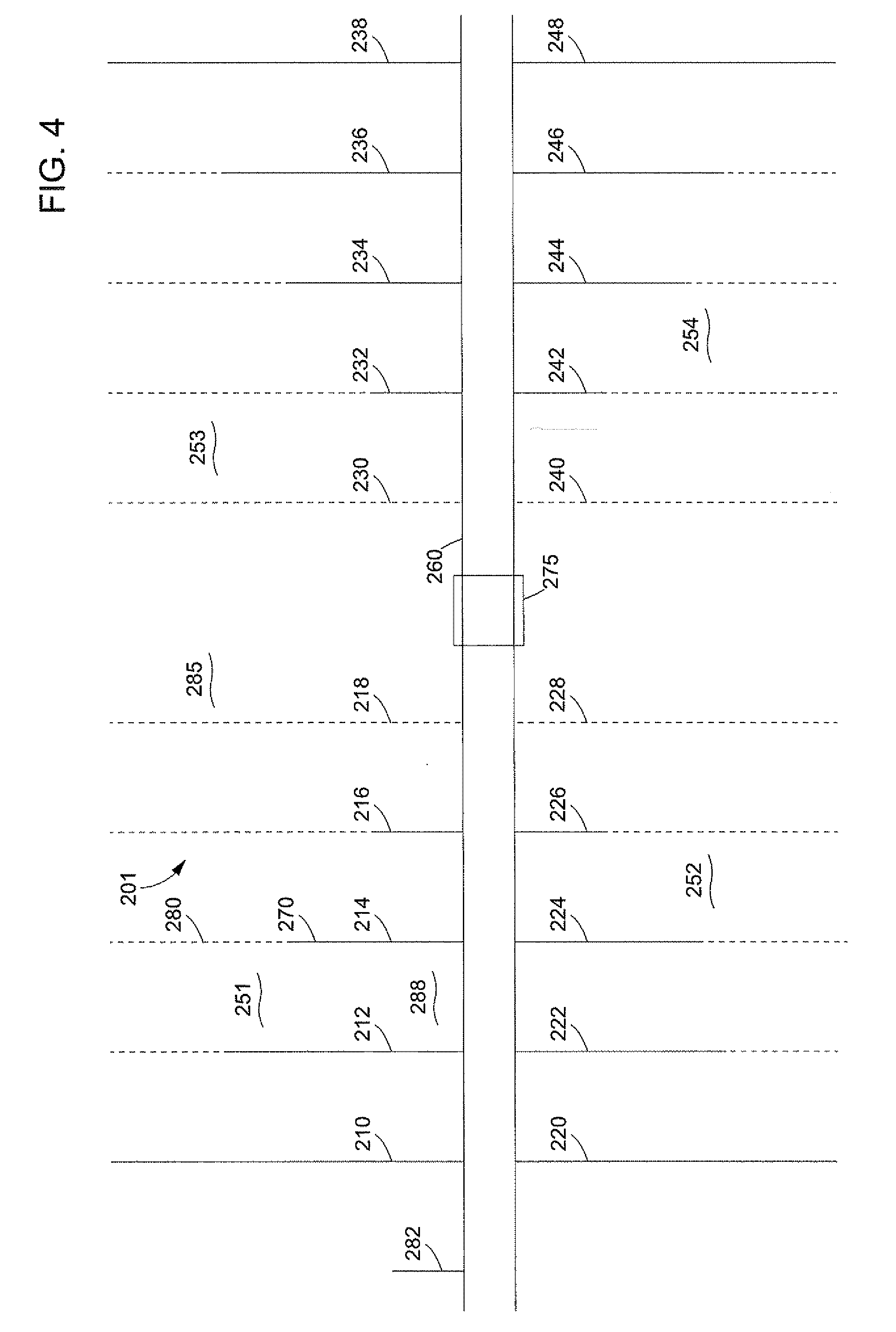
[0058] Referring to FIG. 4, there is schematically shown a top view at surface of a layout of a production field 201 for recovering hydrocarbons from an underground oil sands layer. The Figure shows a plurality of production units 210, 212, 214, 216, 218, 220, 222, 224, 226, 228, 230, 232, 234, 236, 238, 240, 242, 244, 246, 248 in four field sections 251,252,253,254 on either side of a backbone 260. Each production unit can be substantially similar to and operated as described hereinbefore with reference to FIGS. 1-3, and has an injection borehole above a discharge borehole above a refill borehole, overlapping in the top view.
[0059] The production units are in different stages of operation. The solid lines, e.g. 270, indicate a section of a production unit that is producing hydrocarbons (slurry) to a separation plant 275, whereas the dashed lines, e.g. 280, indicate an area that has already been produced and is abandoned, or refilled. Units 218, 228, 230 and 240 were the first units to produce and have already stopped production. Units 210,220,238 and 246 just started production. Remaining units are in an intermediate stage. At 282, boreholes for a future production unit are being drilled. The area 285 that is generally defined by the dashed lines can be referred to as reclaimed area of the production field, and the area 288 generally defined by solid lines can be referred to as producing area of the production field 201. It shall be clear that only one, two or three of the field sections 251-254 may be arranged, or may be developed at different periods in time, and that more or less production units than shown can be provided in a field section.
[0060] The backbone provides for transport of fluids (slurry, tailings) between the production units and the separation plant 275 via suitable pipelines/conduits. It concentrates the surface equipment in a relatively narrow surface area or streak, for easy accessibility and minimum surface impact. This area is moreover typically not or only modestly affected by subsidence.
[0061] The backbone can be between 0.1 and 50 km long, preferably between 0.5 and 20 km, and may grow in the lifetime of a field, which is suitably developed starting with production units close to the separation plant 275. The lateral spacing between production units can be between 10 m and 500 m, preferably between 20 m and 100 m. They can in particular be arranged such that the cavities along adjacent production units join or overlap, or remain separate. Each production unit may have a length of between 50 and 5000 m, in particular between 100 and 2000 m. Areas where it is not desired or possible to produce oil sand can be avoided in the layout.
[0062] With the method described above it is achieved that hydrocarbon fluid is produced from the oil sands layer without removing the overburden layer. Moreover, by refilling the cavities with tailings it is achieved that any subsidence of the overburden layer is reduced to a minimum. In a preferred embodiment, the cavities are refilled with tailings from the produced slurries of water and oil tailings after cleaning at the separation plant. Suitably a binding material like cement is mixed into the tailings.
[0063] In the examples described above, the discharge borehole is provided with a single pump (jet pump 28) for pumping the slurry of fluid and oil sand particles via the discharge borehole to the production station at surface. However, depending on the depth of the cavity and/or other operational parameters, a single pump may not suffice to pump the slurry to surface at an efficient flow rate. In that case, one or more additional pumps can be applied in the discharge borehole. For example, the upper section of the discharge borehole can be provided with a single-stage or multi-stage centrifugal pump driven by a hydraulic or electric motor, to pump the slurry to surface. Such additional pump can be positioned, for example, in the lower end part of the casing provided in the discharge borehole, just above the liner. Alternatively or in addition, an additional jet pump or gas lift can be applied.
[0064] In the examples described above, various boreholes extend from surface locations mutually spaced in horizontal direction. In an alternative arrangement, the boreholes can extend as deviated boreholes from a fewer or a single surface location, or as branch boreholes of a multilateral borehole. Such arrangement can be attractive in applications whereby the surface area is difficult accessible, for example if the oil sands layer is located below a body of water or a swamp area.
* * * * *
D00000
D00001
D00002
D00003
D00004
XML
uspto.report is an independent third-party trademark research tool that is not affiliated, endorsed, or sponsored by the United States Patent and Trademark Office (USPTO) or any other governmental organization. The information provided by uspto.report is based on publicly available data at the time of writing and is intended for informational purposes only.
While we strive to provide accurate and up-to-date information, we do not guarantee the accuracy, completeness, reliability, or suitability of the information displayed on this site. The use of this site is at your own risk. Any reliance you place on such information is therefore strictly at your own risk.
All official trademark data, including owner information, should be verified by visiting the official USPTO website at www.uspto.gov. This site is not intended to replace professional legal advice and should not be used as a substitute for consulting with a legal professional who is knowledgeable about trademark law.