Heat Sink And Method For Manufacturing The Same
Chen; Shyh-Ming
U.S. patent application number 12/821157 was filed with the patent office on 2011-12-29 for heat sink and method for manufacturing the same. Invention is credited to Shyh-Ming Chen.
| Application Number | 20110315366 12/821157 |
| Document ID | / |
| Family ID | 45351422 |
| Filed Date | 2011-12-29 |


View All Diagrams
| United States Patent Application | 20110315366 |
| Kind Code | A1 |
| Chen; Shyh-Ming | December 29, 2011 |
HEAT SINK AND METHOD FOR MANUFACTURING THE SAME
Abstract
A heat sink composed of a fin set and a seat and a method for manufacturing the same are disclosed. One side of the fin set is provided with a plurality of rail rods whose cross sections are of a hook shape. One side of the seat is formed with a plurality of slots corresponding to the rail rods. Thus the fin set and the seat can be assembled by engagement of the rail rods and slots. A press mold is employed to press the rail rods and the slots, thus the rail rods and slots are deformed to make the fin set and seat tightly engage with each other.
| Inventors: | Chen; Shyh-Ming; (Taipei County, TW) |
| Family ID: | 45351422 |
| Appl. No.: | 12/821157 |
| Filed: | June 23, 2010 |
| Current U.S. Class: | 165/185 ; 29/890.03 |
| Current CPC Class: | B21D 53/085 20130101; F28D 2021/0029 20130101; F28F 2275/14 20130101; F28D 15/0275 20130101; F28F 3/06 20130101; Y10T 29/4935 20150115 |
| Class at Publication: | 165/185 ; 29/890.03 |
| International Class: | F28F 7/00 20060101 F28F007/00; B21D 53/02 20060101 B21D053/02 |
Claims
1. A heat sink comprising: a fin set, being provided with a plurality of parallel rail rods on one side thereof, wherein a cross section of each of the rail rods is of a hook shape; and a seat, being formed with a plurality of slots corresponding to the rail rods; wherein the rail rods are separately accommodated in the slots, and the seat and the fin set are tightly assembled together by deformation of the slots.
2. The heat sink of claim 1, wherein the cross section of each of the rail rods is T-shaped and the slots are the same in shape.
3. The heat sink of claim 2, wherein a width of a horizontal bar of each the slot is larger than that of each the rail rod to form a room and a top of each the slot protrudes slightly.
4. The heat sink of claim 1, wherein the cross section of each of the rail rods is L-shaped and the slots are the same in shape.
5. The heat sink of claim 1, wherein the cross section of each of the rail rods is of an inverted-T-shape with an indent at a center of a horizontal bar thereof and the slots are inverted-T-shaped.
6. The heat sink of claim 1, wherein the seat is a cuboid and the fin set has a hollow for accommodating the seat.
7. The heat sink of claim 6, wherein sides of the seat are provided with a plurality of slots and the fin set is provided with corresponding rail rods.
8. The heat sink of claim 6, wherein the cross section of each of the rail rods is inverted-T-shaped and the slots are the same in shape.
9. The heat sink of claim 7, wherein the cross section of each of the rail rods is inverted-T-shaped and the slots are the same in shape.
10. A method for manufacturing a heat sink, comprising the steps of: a) providing a fin set, wherein the fin set is provided with a plurality of parallel rail rods on one side thereof, and a cross section of each of the rail rods is of a hook shape; and b) providing a seat, wherein the seat set is formed with a plurality of slots corresponding to the rail rods; c) embedding the rail rods into the slots; and d) pressing the slots to be deformed, so that the seat and the fin set are tightly assembled together.
11. The method of claim 10, wherein the cross section of each of the rail rods is T-shaped and the slots are the same in shape.
12. The method of claim 11, wherein a width of a horizontal bar of each the slot is larger than that of each the rail rod to form a room and a top of each the slot protrudes slightly.
13. The method of claim 10, wherein the cross section of each of the rail rods is L-shaped and the slots are the same in shape.
14. The method of claim 10, wherein the cross section of each of the rail rods is of an inverted-T-shape with an indent at a center of a horizontal bar thereof and the slots are inverted-T-shaped.
15. The method of claim 10, wherein the seat is a cuboid and the fin set has a hollow for accommodating the seat.
16. The method of claim 15, wherein sides of the seat are provided with a plurality of slots and the fin set is provided with corresponding rail rods.
17. The method of claim 16 wherein the cross section of each of the rail rods is inverted-T-shaped and the slots are the same in shape.
18. The method of claim 17, wherein the cross section of each of the rail rods is inverted-T-shaped and the slots are the same in shape.
Description
BACKGROUND OF THE INVENTION
[0001] 1. Technical Field
[0002] The invention generally relates to heat sinks, particularly to assembling of fins and a seat.
[0003] 2. Related Art
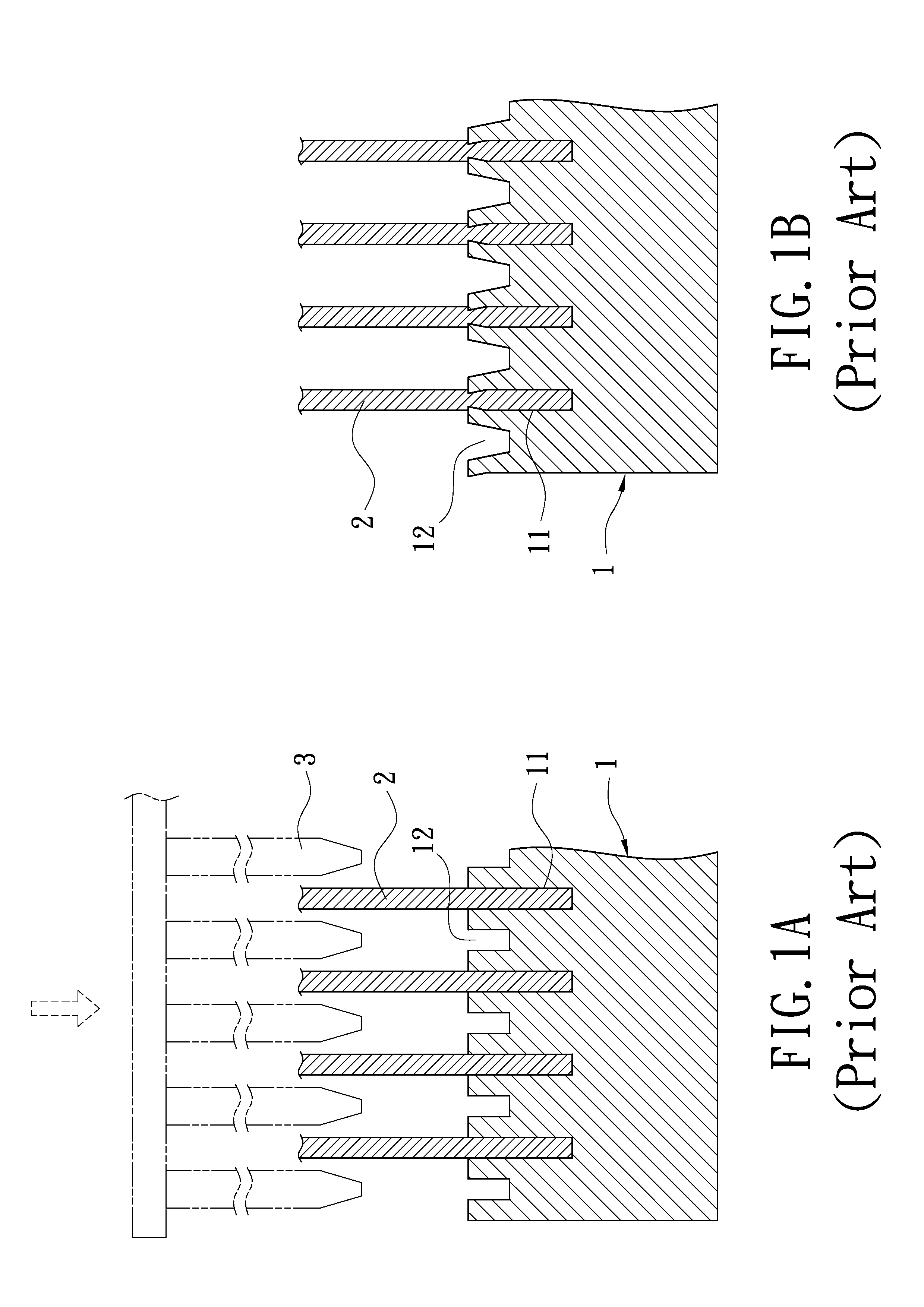
[0004] An ordinary aluminum heat sink is composed of fins and a seat, which are separately formed and then assembled together. And great thermal conductivity must be formed between the fins and seat. FIGS. 1A and 1B show a typical assembling method of fins and seat. One side of the seat 1 is cut by a scraping cutter to form a plurality of parallel deep slots 11 and shallow slots 12, which are alternately arranged. The fins 2 are separately embedded in the deep slots 11. Then a press mold 3 like a knife is inserted into a gap between two fins 2 to press the shallow slots 12. The shallow slots 12 are deformed outwards to tightly nip the fins 2. Thus the fins and seat can be tightly assembled together.
[0005] However, there is a serious drawback in the above method. Both the scraper cutter for cutting the slots 11, 12 and the press mold 3 for pressing the shallow slots 12 must be very sharp. Their knives tend to be blunt, cracked or misshapen, so they must be often maintained and replaced. Not only will the production cost increase but also the replacement operation must interrupt the production process. Therefore, it is very uneconomical to the manufactures.
SUMMARY OF THE INVENTION
[0006] An object of the invention is to reduce production cost and to shorten tact time by not employing scraper cutter and knife-shaped press mold.
[0007] To accomplish the above object, the invention provides a heat sink and a method for manufacturing the same. The heat sink is composed of a fin set and a seat. One side of the fin set is provided with a plurality of rail rods whose cross sections are of a hook shape. One side of the seat is formed with a plurality of slots corresponding to the rail rods. Thus the fin set and the seat can be assembled by engagement of the rail rods and slots. A press mold is employed to press the rail rods and the slots, thus the rail rods and slots are deformed to make the fin set and seat tightly engage with each other.
BRIEF DESCRIPTION OF THE DRAWINGS
[0008] FIGS. 1A and 1B show a conventional method for manufacturing a heat sink;
[0009] FIG. 2 is an exploded perspective view of the first embodiment of the invention;
[0010] FIG. 3 is an assembled perspective view of the first embodiment of the invention;
[0011] FIG. 4 is a cross sectional view of the first embodiment of the invention;
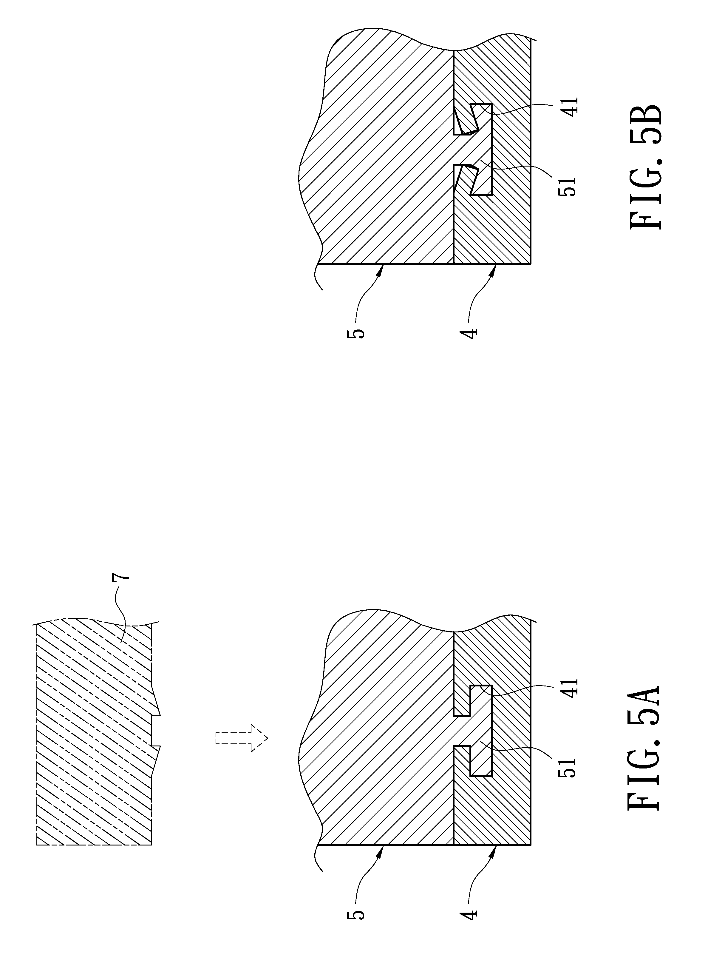
[0012] FIGS. 5A and 5B show a comparison of the first embodiment before and after pressing;
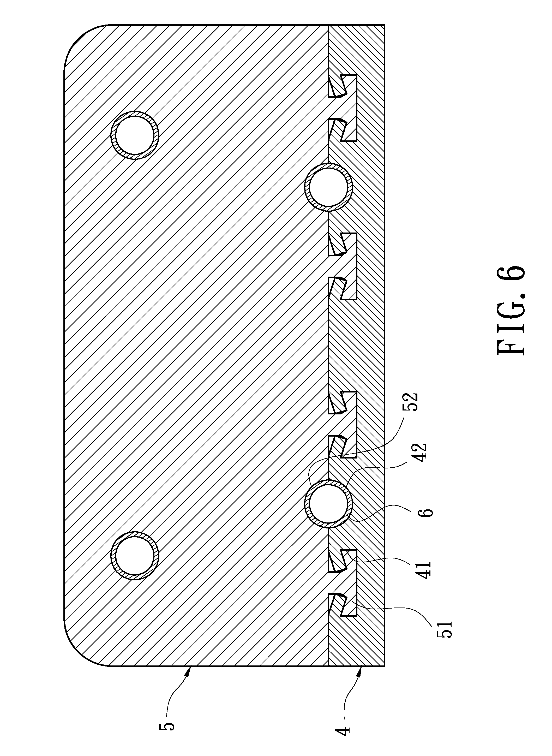
[0013] FIG. 6 is a cross sectional view of the first embodiment after pressing;
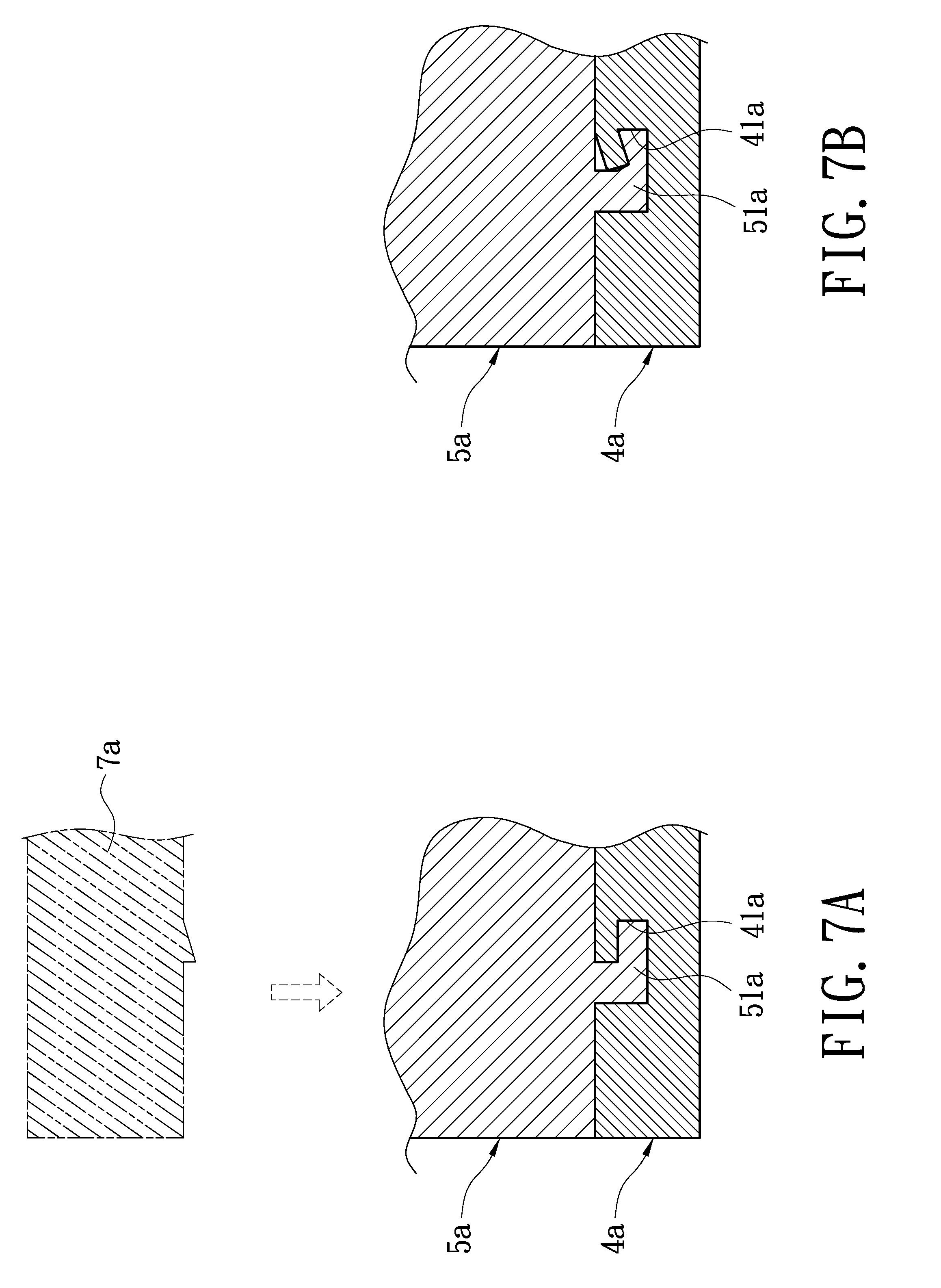
[0014] FIGS. 7A and 7B show a comparison of the second embodiment before and after pressing;
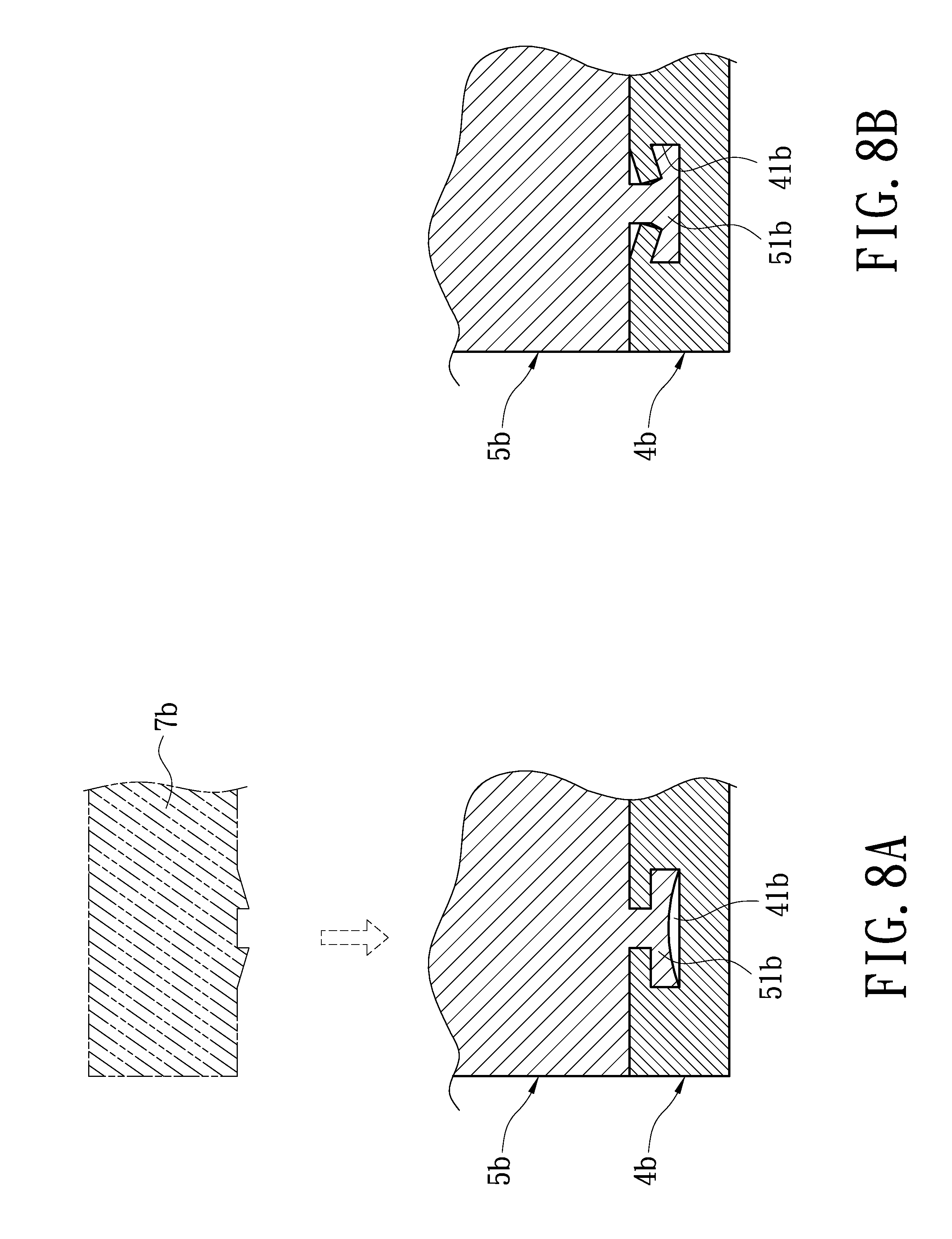
[0015] FIGS. 8A and 8B show a comparison of the third embodiment before and after pressing;
[0016] FIGS. 9A and 9B show a comparison of the fourth embodiment before and after pressing;
[0017] FIGS. 10A and 10B show a comparison of the fifth embodiment before and after pressing; and
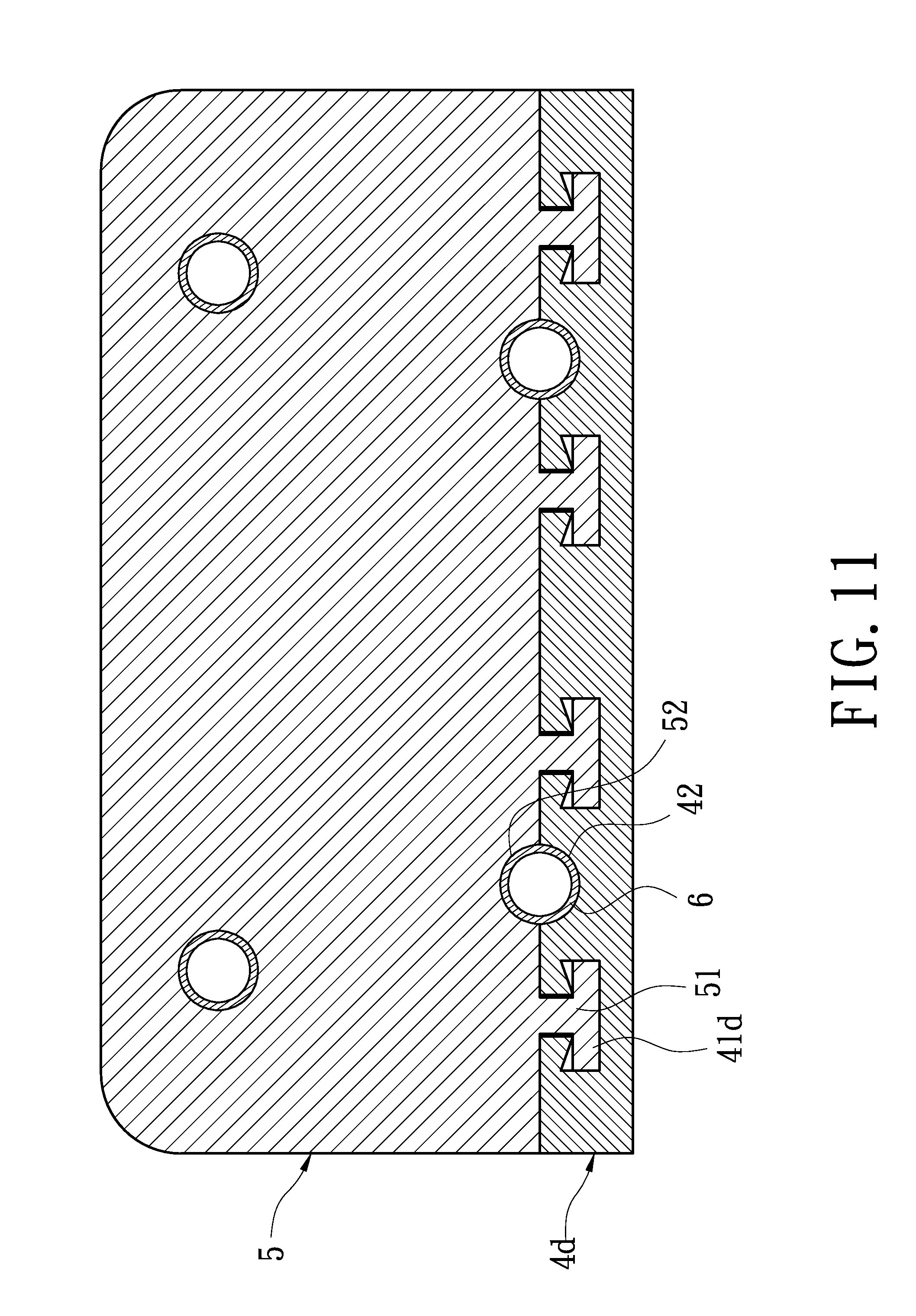
[0018] FIG. 11 is a cross sectional view of the fifth embodiment after pressing.
DETAILED DESCRIPTION OF THE INVENTION
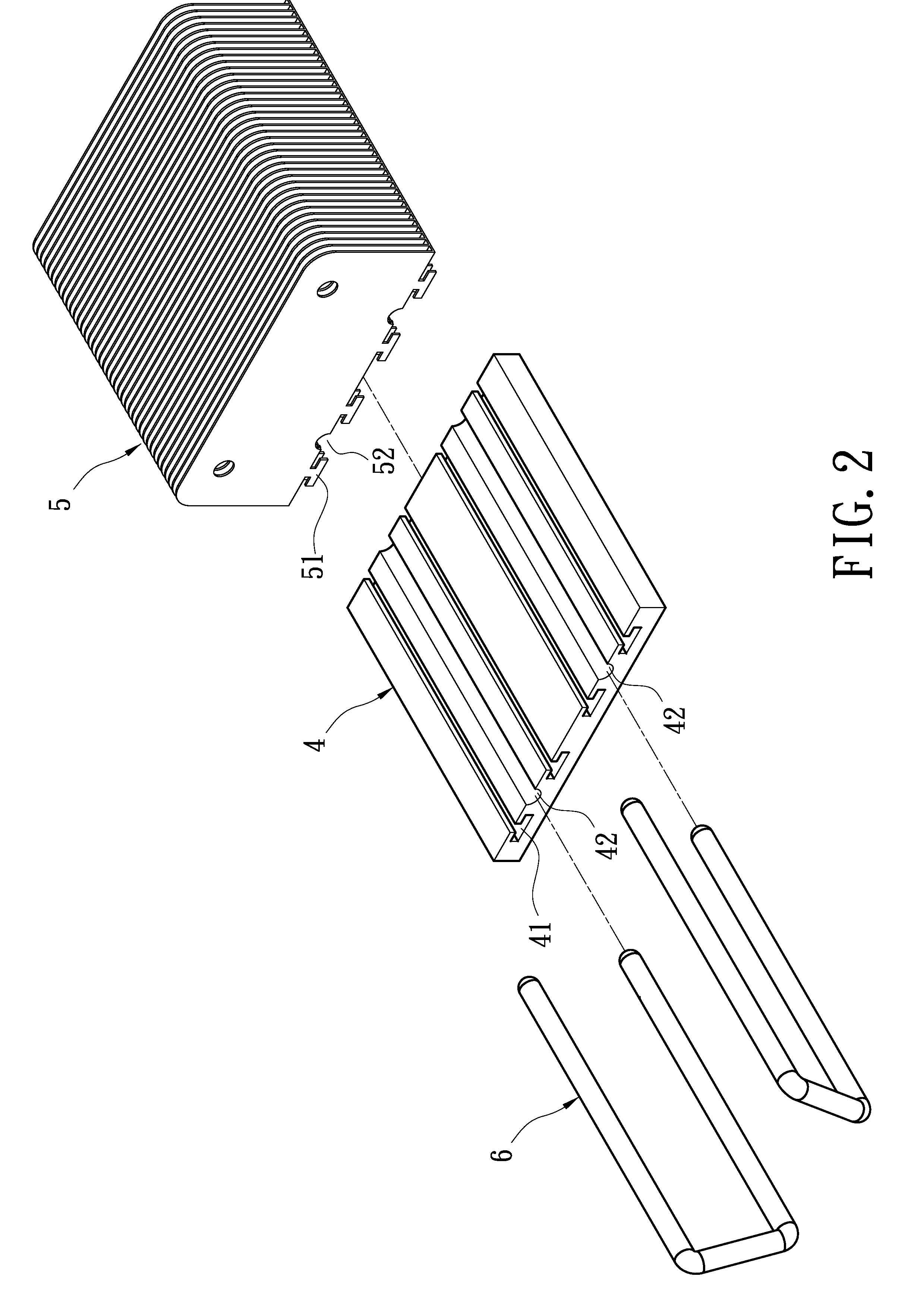
[0019] FIG. 2 shows an exploded view of the first embodiment of the invention. The heat sink of the invention is composed of a seat 4 and a fin set 5. If needed, one or more heat pipes 6 additionally disposed to connect the seat 4 to the fin set 5. The bottom of the fin set 5 to be connected with the seat 4 is provided with a plurality of parallel rail rods 51 whose cross sections are of a hook shape. In the shown embodiment, the cross section of the rail rod 51 is of an inverted-T shape. The fin set 5 is composed of a plurality of fins stacking up with each other. One side of the seat 4 is formed with a plurality of slots 41 corresponding to the rail rods 51. The seat 4 and fin set 5 can be assembled together by embedding the rail rods 51 into the slots 41. Additionally, the seat 4 and fin set 5 may be separately provided with semicircular troughs 42, 52. A pair of semicircular troughs 42, 52 may form a circular trough for accommodating a heat pipe 6.
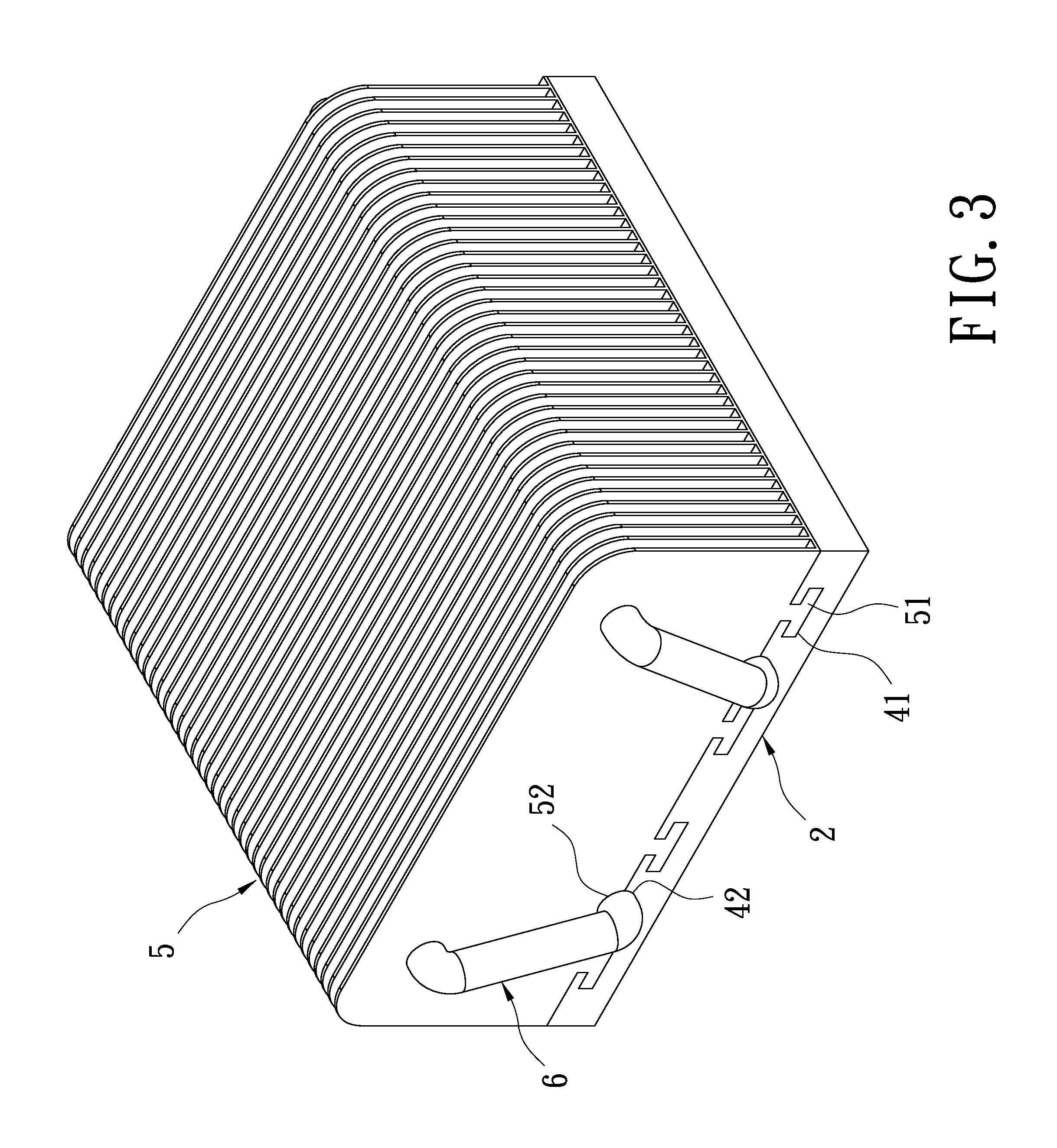
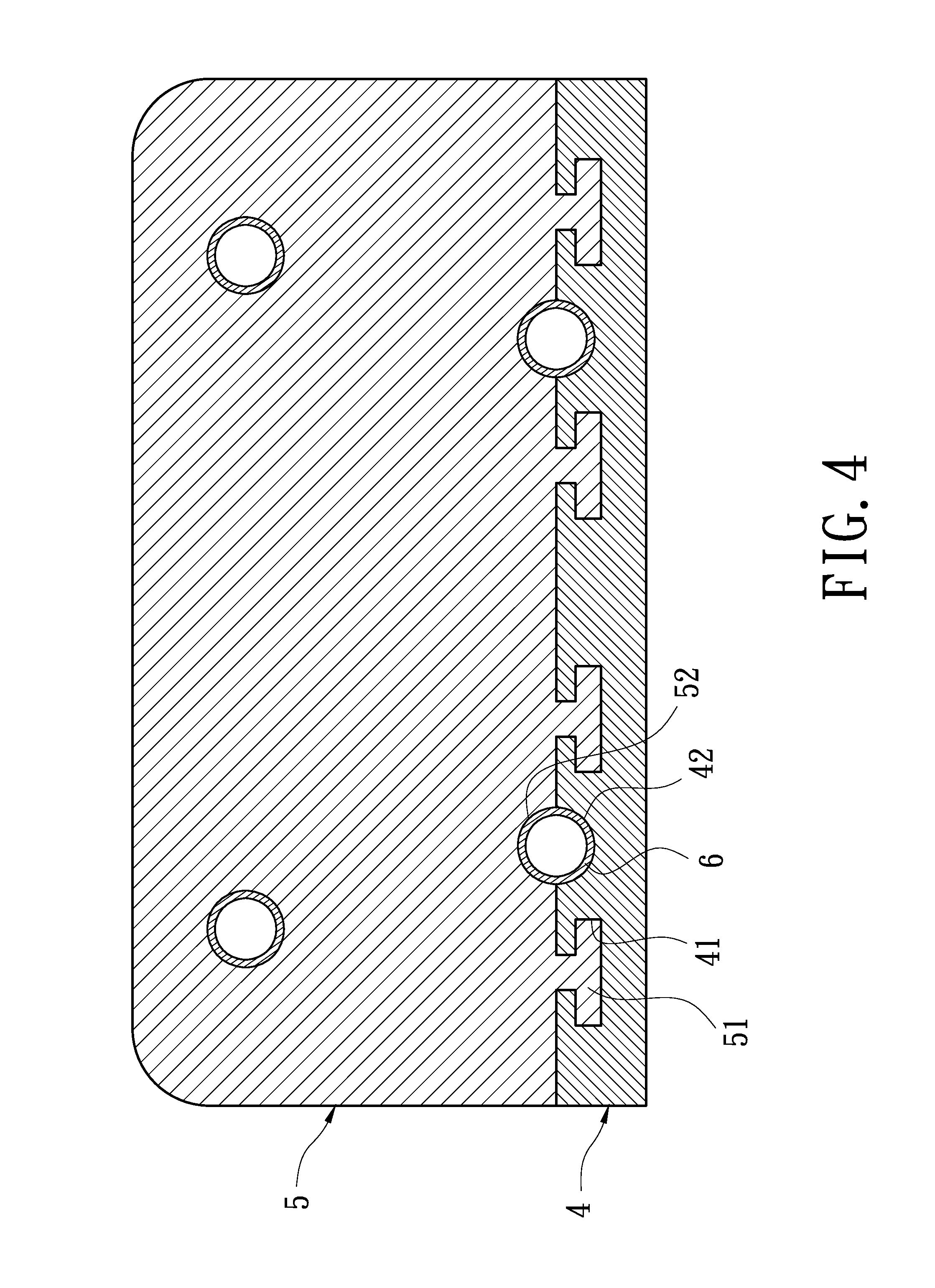
[0020] FIGS. 3 and 4 are an assembled perspective view and cross sectional view of the first embodiment of the invention, respectively. By engaging of the inverted-T-shaped rail rods 51 and slots 41, the seat 4 and fin set 5 has been connected but not tightly assembled yet. Next, as can be seen in FIG. 5A, a press mold 7 is embedded into a gap between two adjacent fins of the fin set 5 to press the slots 41. The press mold 7 has a specific outline for pressing two opposite ends of the inverted-T-shaped slots 41. The slots 41 are thus deformed by this pressing, and the rail rods 51 of the fin set 5 are also deformed. As a result, the seat 4 and fin set 5 are tightly assembled together as shown in FIGS. 5B and 6.
[0021] The shape of the rail rod 51 is not limit to the inverted-T shape as abovementioned. Any other shapes which can perform a hooking effect are available. As shown in FIGS. 7A and 7B, the rail rods 51a have a cross section of an L shape. Of course, shape of the press mold 7a must be modified correspondingly, so that it can press a distal end of the L-shaped slots 41a. Thus the slots 41a are deformed to make the fin set 5a and seat 4a tightly assembled together. FIGS. 8A and 8B show an inverted-T-shaped rail rod 51b with an indent on the center of the horizontal bar. Also, shape of the press mold 7b must be modified correspondingly, so that it can press the two opposite ends of the inverted-T-shaped slots 41b. Thus the slots 41b are deformed to make the fin set 5b and seat 4b tightly assembled together. FIGS. 9A and 9B show a hollow fin set 5c and a cuboidal seat 4c penetrating the fin set 5c. Four sides of the cuboidal seat 4c are separately provided with four T-shaped slots 41c and four corresponding rail rods 51c are formed inside the fin set 5c. The slots 41c are pressed by a press mold to be deformed. Thus the fin set 5c and seat 4c are tightly assembled together. FIGS. 10A and 10B show a fin set 5 with an inverted-T-shaped rail rods 51, which is the same as the embodiment shown in FIG. 2. And the seat 4d is correspondingly formed with inverted-T-shaped slots 41d. But the width of the horizontal bar of the slot 41d is larger than that of the rail rod 51 to form a room. And the top of slot 41d protrudes slightly. When a press mold presses down, the protrudent portion is deformed inwards to push the rail rod 51 to move downwards and to fill the room. Thus the fin set 5 and seat 4d are tightly assembled together.
[0022] It will be appreciated by persons skilled in the art that the above embodiments have been described by way of example only and not in any limitative sense, and that various alterations and modifications are possible without departure from the scope of the invention as defined by the appended claims.
* * * * *
D00000
D00001
D00002
D00003
D00004
D00005
D00006
D00007
D00008
D00009
D00010
D00011
XML
uspto.report is an independent third-party trademark research tool that is not affiliated, endorsed, or sponsored by the United States Patent and Trademark Office (USPTO) or any other governmental organization. The information provided by uspto.report is based on publicly available data at the time of writing and is intended for informational purposes only.
While we strive to provide accurate and up-to-date information, we do not guarantee the accuracy, completeness, reliability, or suitability of the information displayed on this site. The use of this site is at your own risk. Any reliance you place on such information is therefore strictly at your own risk.
All official trademark data, including owner information, should be verified by visiting the official USPTO website at www.uspto.gov. This site is not intended to replace professional legal advice and should not be used as a substitute for consulting with a legal professional who is knowledgeable about trademark law.