Radiator Fan Module
SHIH; Ming-Cyuan ; et al.
U.S. patent application number 13/117706 was filed with the patent office on 2011-12-29 for radiator fan module. This patent application is currently assigned to FORCECON TECHNOLOGY CO., LTD.. Invention is credited to Jhong-Yan Chang, Sin-Wei He, Tzu-Hsin Huang, Ming-Cyuan SHIH.
| Application Number | 20110315359 13/117706 |
| Document ID | / |
| Family ID | 45351418 |
| Filed Date | 2011-12-29 |


| United States Patent Application | 20110315359 |
| Kind Code | A1 |
| SHIH; Ming-Cyuan ; et al. | December 29, 2011 |
RADIATOR FAN MODULE
Abstract
A radiator fan module has a fan assembly, cooling fin and heat conductor. The fan assembly has a shell seat and fan blade, an air outlet is set at one side of the shell seat, the cooling fin is set correspondingly to the outlet, and the cooling end of the conductor is mated with the fin. The outlet forms an inward extended wall, an outward extended wall and an extended inner space set between the outlet and fan blade. The outlet has a width-reducing pattern. A notched space is formed externally between the inward extended wall and shell seat. An inward extended heat conductor is formed by the extension of the inner end of the cooling fin and is located within the range of the extended inner space, and provided with a blade corresponding side that is located correspondingly to a peripheral position of the blade.
| Inventors: | SHIH; Ming-Cyuan; (Jhubei City, TW) ; He; Sin-Wei; (Jhudong Township, TW) ; Chang; Jhong-Yan; (Hsinchu City, TW) ; Huang; Tzu-Hsin; (Hsinchu City, TW) |
| Assignee: | FORCECON TECHNOLOGY CO.,
LTD. Chu Pei City TW |
| Family ID: | 45351418 |
| Appl. No.: | 13/117706 |
| Filed: | May 27, 2011 |
| Current U.S. Class: | 165/121 |
| Current CPC Class: | F28F 1/20 20130101; H01L 2924/00 20130101; H01L 2924/0002 20130101; H01L 23/467 20130101; F28D 15/0275 20130101; H01L 23/427 20130101; F28D 15/0233 20130101; H01L 2924/0002 20130101; F28D 2021/0028 20130101 |
| Class at Publication: | 165/121 |
| International Class: | F28F 13/00 20060101 F28F013/00 |
Foreign Application Data
| Date | Code | Application Number |
|---|---|---|
| Jun 23, 2010 | TW | 099211888 |
Claims
1. A radiator fan module, comprising: a fan assembly, a cooling fin and a heat conductor; the fan assembly comprises of a shell seat and fan blade pivoted into the shell seat; an air inlet is set onto at least one surface of the shell seat, and an air outlet at one side; the cooling fin is set correspondingly to the air outlet; the cooling end of the heat conductor is mated with the cooling fin, while the heated end of the heat conductor is extended outwards, of which: the air outlet is protruded to form an inward extended wall, an outward extended wall and an extended inner space set between the air outlet and fan blade; the air outlet has a width-reducing pattern, such that the inward extended wall is located nearby the corresponding center of the fan blade; a notched space is formed externally between the inward extended wall and shell seat; an inward extended heat conductor is formed by the extension of the inner end of the cooling fin; the inward extended heat conductor is located within the range of the extended inner space, and provided with a fan blade corresponding side that is located correspondingly to a peripheral position of the fan blade.
2. The structure defined in claim 1, wherein said cooling fin is made of multiple heat-conducting fins arranged vertically or horizontally.
3. The structure defined in claim 1, wherein said heat conductor is either a heat pipe or hot plate.
4. The structure defined in claim 1, wherein the cooling end of said heat conductor can be mated with either side of the cooling fin.
5. The structure defined in claim 1, wherein the fan blade corresponding side of the inward extended heat conductor is available with either of curved, stepped or corrugated surface.
6. The structure defined in claim 1, wherein said heat conductor is a flat heat pipe; an opening is set onto the outward extended wall of the air outlet for exposing one side of the cooling fin; the cooling end of the heat conductor with a pattern of flat heat pipe is set into a vertical surface for abutting onto the exposing side of the cooling fin, whilst the heated end of the heat conductor is set into a horizontal surface by turning around 90.degree..
7. The structure defined in claim 1, wherein an inward bulging margin is set at the mating point of the inward extended wall and the shell seat.
8. The structure defined in claim 1, wherein one side of the cooling fin includes a vertical wall flange; a notched portion is set at one side of the air outlet for exposing of the vertical wall flange of the cooling fin; and a heat-conducting block is set on the external surface of the vertical wall flange; the heat-conducting block contains a mating surface and an insertion slot; the mating surface is incorporated onto external surface of the vertical wall flange of the cooling fin, and the insertion slot is used for inserting the cooling end of the heat conductor.
Description
CROSS-REFERENCE TO RELATED U.S. APPLICATIONS
[0001] Not applicable.
STATEMENT REGARDING FEDERALLY SPONSORED RESEARCH OR DEVELOPMENT
[0002] Not applicable.
NAMES OF PARTIES TO A JOINT RESEARCH AGREEMENT
[0003] Not applicable.
REFERENCE TO AN APPENDIX SUBMITTED ON COMPACT DISC
[0004] Not applicable.
BACKGROUND OF THE INVENTION
[0005] 1. Field of the Invention
[0006] The present invention relates generally to a radiator fan module, and more particularly to an innovative one which is designed to reduce the width and area of its air outlet with outstanding heat dissipation efficacies.
[0007] 2. Description of Related Art Including Information Disclosed Under 37 CFR 1.97 and 37 CFR 1.98.
[0008] The radiator fan module is of great importance to computer products since it directly affects a CPU's performance, stability and service life. So, the radiator fan module is structurally designed in tune with the design trend of computer products.
[0009] The present invention is intended to improve a radiator fan module, which comprises a fan assembly, cooling fin and heat pipe. Such a radiator fan module is now widely applied to laptops. Yet some problems of the structural design still remain unresolved. FIG. 1 illustrates a radiator fan module of the prior art, which comprises a fan assembly 11, cooling fin 12 and heat pipe 13. A side-blown air outlet 113 of the fan assembly 11 almost as wide as the seat shell 112 is formed at one side of the seat shell 112, and the cooling fin 12 is arranged correspondingly to the side-blown air outlet 113. The cooling end 131 of the heat pipe 13 is abutted between the cooling fin 12 and side-blown air outlet 113. However, the following shortcomings of the conventional radiator fan module are found during actual applications.
[0010] In addition to an interface of side-blown air outlet 113, the laptop is also provided with optimal assembly position for CD-ROM, network card, video extension terminal and USB drive. However, when a compact laptop is designed, the available area of its periphery is reduced significantly. When the assembly area of aforementioned interfaces is minimized, the type design of the radiator fan module is a key element. In other words, whether the air outlet of the radiator fan module can be further reduced will directly affect the degree of compactness of the laptop. Even so, there is still a technical consideration as to whether the heat dissipation effect of the radiator fan module is affected.
[0011] Thus, to overcome the aforementioned problems of the prior art, it would be an advancement if the art to provide an improved structure that can significantly improve the efficacy.
[0012] Therefore, the inventor has provided the present invention of practicability after deliberate design and evaluation based on years of experience in the production, development and design of related products.
BRIEF SUMMARY OF THE INVENTION
[0013] The enhanced efficacy of the present invention is as follows:
[0014] Based on the unique construction of the present invention wherein the "radiator fan module" allows its air outlet to be set into protruding and width-reducing pattern, such that a notched space is formed externally between the inward extended wall and shell seat, and an inward extended heat conductor is formed by the extension of the inner end of the cooling fin. Besides, the inward extended heat conductor is extended from the inner end of the cooling fin to the extended inner space, thus making up width reduction of the cooling fin arising from area reduction of the air outlet for better heat dissipation effect. The notched space can provide a bigger space for accommodating the connectors within the laptop. Thus, the radiator fan module of the present invention allows to reduce greatly the width and area of its air outlet without loss of heat dissipation effect, such that the radiator fan module can be more flexibly applied to compact computer products with improved applicability and industrial benefits.
[0015] Although the invention has been explained in relation to its preferred embodiment, it is to be understood that many other possible modifications and variations can be made without departing from the spirit and scope of the invention as hereinafter claimed.
BRIEF DESCRIPTION OF THE SEVERAL VIEWS OF THE DRAWINGS
[0016] FIG. 1 is a perspective view of a conventional radiator fan module.
[0017] FIG. 2 is an assembled perspective view of the preferred embodiment of the present invention.
[0018] FIG. 3 is a partially exploded perspective view of the preferred embodiment of the present invention.
[0019] FIG. 4 is an exploded perspective view of the preferred embodiment of the present invention.
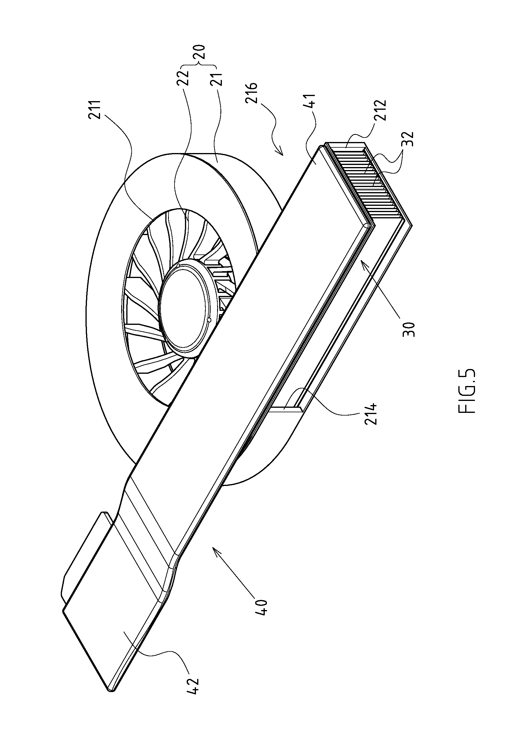
[0020] FIG. 5 is an assembled perspective view of another preferred embodiment of the present invention.
[0021] FIG. 6 is a partially exploded perspective view of another preferred embodiment of the present invention.
[0022] FIG. 7 is an exploded perspective view of another preferred embodiment of the present invention.
[0023] FIG. 8 is an exploded perspective view of another preferred embodiment of the present invention.
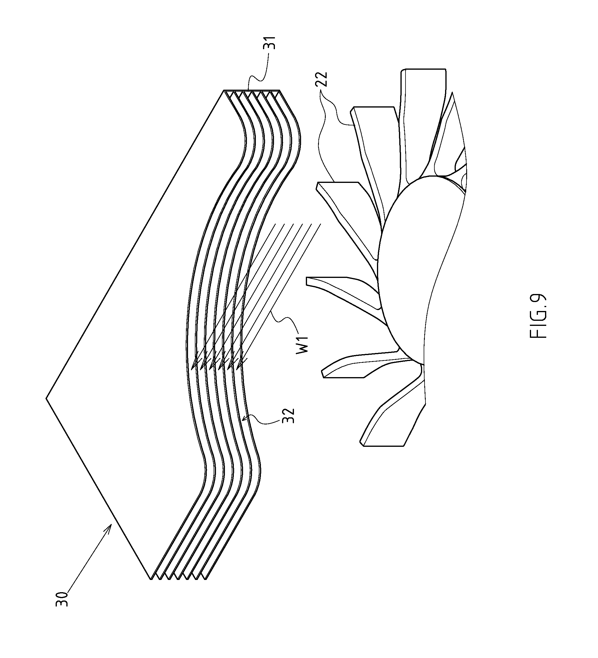
[0024] FIG. 9 is a schematic view 1 of the present invention wherein the cooling fin is configured transversely.
[0025] FIG. 10 is a schematic view 2 of the present invention wherein the cooling fin is configured transversely.
DETAILED DESCRIPTION OF THE INVENTION
[0026] FIGS. 2-4 depict preferred embodiments of a radiator fan module of the present invention, which, however, are provided for only explanatory objective for patent claims. Said radiator fan module comprises: a fan assembly 20, a cooling fin 30 and a heat conductor 40. The fan assembly 20 comprises of a shell seat 21 and fan blade 22 pivoted into the shell seat 21. An air inlet 211 is set onto at least one surface of the shell seat 21 (top surface in the preferred embodiment), and an air outlet 212 at one side. The cooling fin 30 is set correspondingly to the air outlet 212. The cooling end 41 of the heat conductor 40 is mated with the cooling fin 30, while the heated end 42 of the heat conductor 40 is extended outwards, of which:
[0027] the air outlet 212 is protruded to form an inward extended wall 213, an outward extended wall 214 and an extended inner space 215 set between the air outlet 212 and fan blade 22;
[0028] the air outlet 212 is designed into a width-reducing pattern, such that the inward extended wall 213 is located nearby the corresponding center of the fan blade 22;
[0029] a notched space 216, formed externally between the inward extended wall 213 and shell seat 21;
[0030] an inward extended heat conductor 31, formed by the extension of the inner end of the cooling fin 30; the inward extended heat conductor 31 is located within the range of the extended inner space 215, and provided with a fan blade corresponding side 311 that is located correspondingly to a peripheral position of the fan blade 22.
[0031] Of which, the cooling fin 30 is made of multiple heat-conducting fins 32 arranged vertically or horizontally.
[0032] Of which, said heat conductor 40 is either a heat pipe (including: round or flat heat pipe) or hot plate. FIGS. 2-4 illustrate the heat conductor 40 with a pattern of flat heat pipe, while FIGS. 5-7 illustrate the heat conductor 40 with a pattern of hot plate.
[0033] Of which, the cooling end 41 of the heat conductor 40 can be mated with either side of the cooling fin 30 (including: upper, lower, left and right sides).
[0034] Of which, the fan blade corresponding side 311 of the inward extended heat conductor 31 is available with either of a curved, stepped or corrugated surface. Referring to FIGS. 3, 4, said fan blade corresponding side 311 is configured with a curved surface. Referring also to FIGS. 6, 7, said fan blade corresponding side 311 is configured with a stepped surface.
[0035] Referring to FIGS. 2, 3, 4, said heat conductor 40 is a flat heat pipe. An opening 217 is set onto the outward extended wall 214 of the air outlet 212 for exposing one side of the cooling fin 30. The cooling end 41 of the heat conductor 40 with a pattern of flat heat pipe is set into a vertical surface for abutting onto the exposing side of the cooling fin 30, whilst the heated end 42 of the heat conductor 40 is set into a horizontal surface by turning around 90.degree..
[0036] Based on the aforementioned structural configuration, the core of said radiator fan module lies in that, the air outlet 212 is designed into a protruding and width-reducing pattern, such that a notched space 216 is located externally between the inward extended wall 213 and shell seat 21. Moreover, the inward extended heat conductor 31 is extended from the inner end of the cooling fin 30. With the design of the radiator fan module, when a compact laptop is designed and the available area of its periphery is reduced significantly, the air outlet 212 can be designed into a protruding and width-reducing pattern, such that the area of radiator fan module's air outlet can be reduced greatly. Besides, the inward extended heat conductor 31 is extended from the inner end of the cooling fin 30 to the extended inner space 215, thus making up substantial width reduction of the cooling fin arising from area reduction of the air outlet 212 for better heat dissipation effect. Also, a notched space 216 is located externally between the inward extended wall 213 and shell seat 21. The notched space 216 can provide a bigger space for accommodating the connectors within the laptop.
[0037] Of which, an inward bulging margin 23 (shown in FIGS. 3, 4, 6, 7) is set at the mating point of the inward extended wall 213 and the shell seat 21. With the design of the margin 23, an air pressure point close to the fan blade 22 is formed in the shell seat 21, so that when internal air flow is driven by the fan blade 22 to pass through the margin 23, air diversion towards the air outlet 212 can be generated laterally.
[0038] Referring to FIG. 8, one side of the cooling fin 30 includes a vertical wall flange 31. A notched portion 24 is set at one side of the air outlet 212 for exposing of the vertical wall flange 31 of the cooling fin 30. A heat-conducting block 50 (a copper block) is set on the external surface of the vertical wall flange 31. The heat-conducting block 50 contains a mating surface 51 and an insertion slot 52 (available with through-hole, blind hole or grooved patterns). The mating surface 51 is incorporated onto external surface of the vertical wall flange 31 of the cooling fin 30, and the insertion slot 52 is used for inserting the cooling end 41 of the heat conductor 40. With the arrangement of the heat-conducting block 50, the heat transfer contact area between the cooling end 41 of the heat conductor 40 and the cooling fin 30 can be expanded for further improving heat radiation effect.
[0039] Moreover, when the cooling fin 30 is configured transversely (when the radiator fan is located transversely), said cooling fin 30 and the vertical surface of the fan blade 22 of the fan assembly 20 are arranged in perpendicular to each other or in a staggered state (note: this depends on the vertical angle of the fan blade 22). With the configuration design of the cooling fin, as shown in FIG. 10, when the fan assembly 20 is operated, the fan blade 22 is rotated (indicated by arrow L1) to push air stream W1 towards the cooling fin 30 of the air outlet 212. Referring to FIG. 9, the air stream W1 can pass through simultaneously the exhaust channels 32 of the cooling fin 30, whilst the powder W2 in the air stream W1 is concentrated onto two sides within the air outlet 212 (shown in FIG. 6), thus reducing the stacking area of the powder W2, and maintaining the maximum exhaust area and volume of the air outlet 212 to keep the optimum heat radiation effect of the radiator fan.
* * * * *
D00000
D00001
D00002
D00003
D00004
D00005
D00006
D00007
D00008
D00009
D00010
XML
uspto.report is an independent third-party trademark research tool that is not affiliated, endorsed, or sponsored by the United States Patent and Trademark Office (USPTO) or any other governmental organization. The information provided by uspto.report is based on publicly available data at the time of writing and is intended for informational purposes only.
While we strive to provide accurate and up-to-date information, we do not guarantee the accuracy, completeness, reliability, or suitability of the information displayed on this site. The use of this site is at your own risk. Any reliance you place on such information is therefore strictly at your own risk.
All official trademark data, including owner information, should be verified by visiting the official USPTO website at www.uspto.gov. This site is not intended to replace professional legal advice and should not be used as a substitute for consulting with a legal professional who is knowledgeable about trademark law.