Heat Sink Wind Guide Structure And Thermal Module Thereof
Lin; Sheng-Huang
U.S. patent application number 12/824439 was filed with the patent office on 2011-12-29 for heat sink wind guide structure and thermal module thereof. Invention is credited to Sheng-Huang Lin.
| Application Number | 20110315357 12/824439 |
| Document ID | / |
| Family ID | 45351416 |
| Filed Date | 2011-12-29 |


View All Diagrams
| United States Patent Application | 20110315357 |
| Kind Code | A1 |
| Lin; Sheng-Huang | December 29, 2011 |
HEAT SINK WIND GUIDE STRUCTURE AND THERMAL MODULE THEREOF
Abstract
A heat sink wind guide structure and a thermal module thereof. The heat sink wind guide structure includes a heat sink having multiple radiating fins and a wind incoming side. Each two adjacent radiating fins define therebetween a heat dissipation flow way in communication with the wind incoming side. The radiating fins include a first radiating fin and a second radiating fin, which are respectively positioned on two opposite outer sides of the heat sink. The first radiating fin has a first extension end and the second radiating fin has a second extension end. The heat sink is assembled with a fan to form the thermal module. By means of the first and second extension ends, the heat of the heat sink can be dissipated quickly and the heat dissipation airflow can be exhausted from many sides of the heat sink to greatly enhance heat dissipation efficiency.
| Inventors: | Lin; Sheng-Huang; (Sinjhuang City, TW) |
| Family ID: | 45351416 |
| Appl. No.: | 12/824439 |
| Filed: | June 28, 2010 |
| Current U.S. Class: | 165/121 ; 165/185 |
| Current CPC Class: | H01L 2924/0002 20130101; F28F 2215/00 20130101; F28F 2255/16 20130101; F28F 2250/08 20130101; H01L 2924/00 20130101; H01L 23/3672 20130101; F28D 15/0233 20130101; F28F 21/084 20130101; F28F 1/32 20130101; H01L 23/467 20130101; H01L 23/427 20130101; H01L 2924/0002 20130101 |
| Class at Publication: | 165/121 ; 165/185 |
| International Class: | F28F 13/00 20060101 F28F013/00; F28F 7/00 20060101 F28F007/00 |
Claims
1. A heat sink wind guide structure comprising a heat sink having multiple radiating fins and a wind incoming side, each two adjacent radiating fins defining therebetween a heat dissipation flow way in communication with the wind incoming side, the radiating fins including a first radiating fin and a second radiating fin, which are respectively positioned on two opposite outer sides of the heat sink, the first radiating fin having a first extension end protruding from the first radiating fin, the second radiating fin having a second extension end protruding from the second radiating fin.
2. The heat sink wind guide structure as claimed in claim 1, wherein a first wind guide wing and a second wind guide wing are respectively connected to two sides of the first extension end, the first extension end and the first and second wind guide wings together defining a first wind guide passageway, a third wind guide wing and a fourth wind guide wing being respectively connected to two sides of the second extension end, the second extension end and the third and fourth wind guide wings together defining a second wind guide passageway.
3. The heat sink wind guide structure as claimed in claim 1, wherein the heat sink is composed of multiple radiating fins, which are piled up.
4. The heat sink wind guide structure as claimed in claim 1, wherein the heat sink is an extruded aluminum heat sink.
5. A thermal module with heat sink wind guide structure, comprising: a heat sink having multiple radiating fins and a wind incoming side, each two adjacent radiating fins defining therebetween a heat dissipation flow way in communication with the wind incoming side, the radiating fins including a first radiating fin and a second radiating fin, which are respectively positioned on two opposite outer sides of the heat sink, the first radiating fin having a first extension end protruding from the first radiating fin, the second radiating fin having a second extension end protruding from the second radiating fin; and a fan mated with the wind incoming side of the heat sink.
6. The thermal module with heat sink wind guide structure as claimed in claim 5, wherein a first wind guide wing and a second wind guide wing are respectively connected to two sides of the first extension end, the first extension end and the first and second wind guide wings together defining a first wind guide passageway, a third wind guide wing and a fourth wind guide wing being respectively connected to two sides of the second extension end, the second extension end and the third and fourth wind guide wings together defining a second wind guide passageway.
7. The thermal module with heat sink wind guide structure as claimed in claim 5, wherein the heat sink is composed of multiple radiating fins, which are piled up.
8. The thermal module with heat sink wind guide structure as claimed in claim 5, wherein, the heat sink is an extruded aluminum heat sink.
9. The thermal module with heat sink wind guide structure as claimed in claim 5, wherein the heat sink has at least one heat pipe extending through the heat sink.
10. The thermal module with heat sink wind guide structure as claimed in claim 9, wherein the heat sink has a heat absorption section and a heat dissipation section, two ends of the heat pipe respectively passing through the heat absorption section and heat dissipation section of the heat sink.
Description
FIELD OF THE INVENTION
[0001] The present invention relates to a heat sink wind guide structure and a thermal module thereof, and more particularly to a thermal module with heat sink wind guide structure, in which the heat dissipation airflow is exhausted from many sides of the heat sink to greatly enhance heat dissipation efficiency.
BACKGROUND OF THE INVENTION
[0002] Following the advance of semiconductor technologies, the volume of integrated circuit has become smaller and smaller. In order to process more data, the current integrated circuit with the same volume contains several times more calculation components than the conventional integrated circuit. The larger the number of the calculation components contained in the integrated circuit is, the greater the heat generated by the calculation components in working. As exemplified with a common central processor, in a full-load state, the heat generated by the central processor may burn down the entire central processor. Therefore, heat dissipation of the integrated circuit has become a critical topic.
[0003] Please refer to FIG. 1, which is a perspective assembled view of a conventional thermal module 1. The conventional thermal module 1 is composed of a fan 11 and a cooperative heat sink 12. The fan 11 is mated with one side of the heat sink 12. The heat sink 12 has multiple radiating fins 121 defining therebetween multiple heat dissipation flow ways 122. The fan 11 has a wind exit side 111 adapted to the heat dissipation flow ways 122.
[0004] Two ends of the heat dissipation flow way 122 between the radiating fins 121 are open. In operation, the fan 11 forcedly guides heat dissipation airflow 2 to dissipate heat from the heat sink 12. The heat dissipation airflow 2 goes from the wind exit side 111 into the heat dissipation flow ways 122. Then the heat dissipation airflow 2 is exhausted from two ends of the heat dissipation flow ways 122 to achieve heat dissipation effect. However, the heat dissipation airflow 2 can only flow out from two sides of the heat sink 12. Therefore, the heat dissipation efficiency is quite limited and the heat may accumulate in the heat sink 12 to lower the heat dissipation effect. Moreover, such thermal module 1 is only applicable to one single heat source. Accordingly, the conventional thermal module 1 has the following shortcomings: [0005] 1. The heat dissipation efficiency of the conventional thermal module is low. [0006] 2. The heat is likely to accumulate in the heat sink of the conventional thermal module. [0007] 3. The heat dissipation effect of the conventional thermal module is poor.
SUMMARY OF THE INVENTION
[0008] A primary object of the present invention is to provide a heat sink wind guide structure, in which the heat dissipation airflow is exhausted from many sides of the heat sink to greatly enhance heat dissipation efficiency.
[0009] A further object of the present invention is to provide a thermal module with heat sink wind guide structure, in which the heat dissipation airflow is exhausted from many sides of the heat sink to greatly enhance heat dissipation efficiency.
[0010] To achieve the above and other objects, the heat sink wind guide structure of the present invention includes a heat sink having multiple radiating fins and a wind incoming side. Each two adjacent radiating fins define therebetween a heat dissipation flow way in communication with the wind incoming side. The radiating fins include a first radiating fin and a second radiating fin, which are respectively positioned on two opposite outer sides of the heat sink. The first radiating fin has a first extension end protruding from the first radiating fin. The second radiating fin has a second extension end protruding from the second radiating fin.
[0011] The thermal module with heat sink wind guide structure of the present invention includes a heat sink and a fan. The heat sink has multiple radiating fins and a wind incoming side. Each two adjacent radiating fins define therebetween a heat dissipation flow way in communication with the wind incoming side. The radiating fins include a first radiating fin and a second radiating fin, which are respectively positioned on two opposite outer sides of the heat sink. The first radiating fin has a first extension end protruding from the first radiating fin. The second radiating fin has a second extension end protruding from the second radiating fin. The fan is mated with the wind incoming side of the heat sink.
BRIEF DESCRIPTION OF THE DRAWINGS
[0012] The structure and the technical means adopted by the present invention to achieve the above and other objects can be best understood by referring to the following detailed description of the preferred embodiments and the accompanying drawings, wherein:
[0013] FIG. 1 is a perspective assembled view of a conventional thermal module;
[0014] FIG. 2a is a perspective view of a first embodiment of the heat sink wind guide structure of the present invention;
[0015] FIG. 2b is a top view of the first embodiment of the heat sink wind guide structure of the present invention;
[0016] FIG. 3a is a perspective view of a second embodiment of the heat sink wind guide structure of the present invention;
[0017] FIG. 3b is a top view of the second embodiment of the heat sink wind guide structure of the present invention;
[0018] FIG. 4a is a perspective exploded view of a first embodiment of the thermal module of the present invention;
[0019] FIG. 4b is a perspective assembled view of the first embodiment of the thermal module of the present invention;
[0020] FIG. 4c is a right view of the first embodiment of the thermal module of the present invention;
[0021] FIG. 5a is a perspective exploded view of a second embodiment of the thermal module of the present invention;
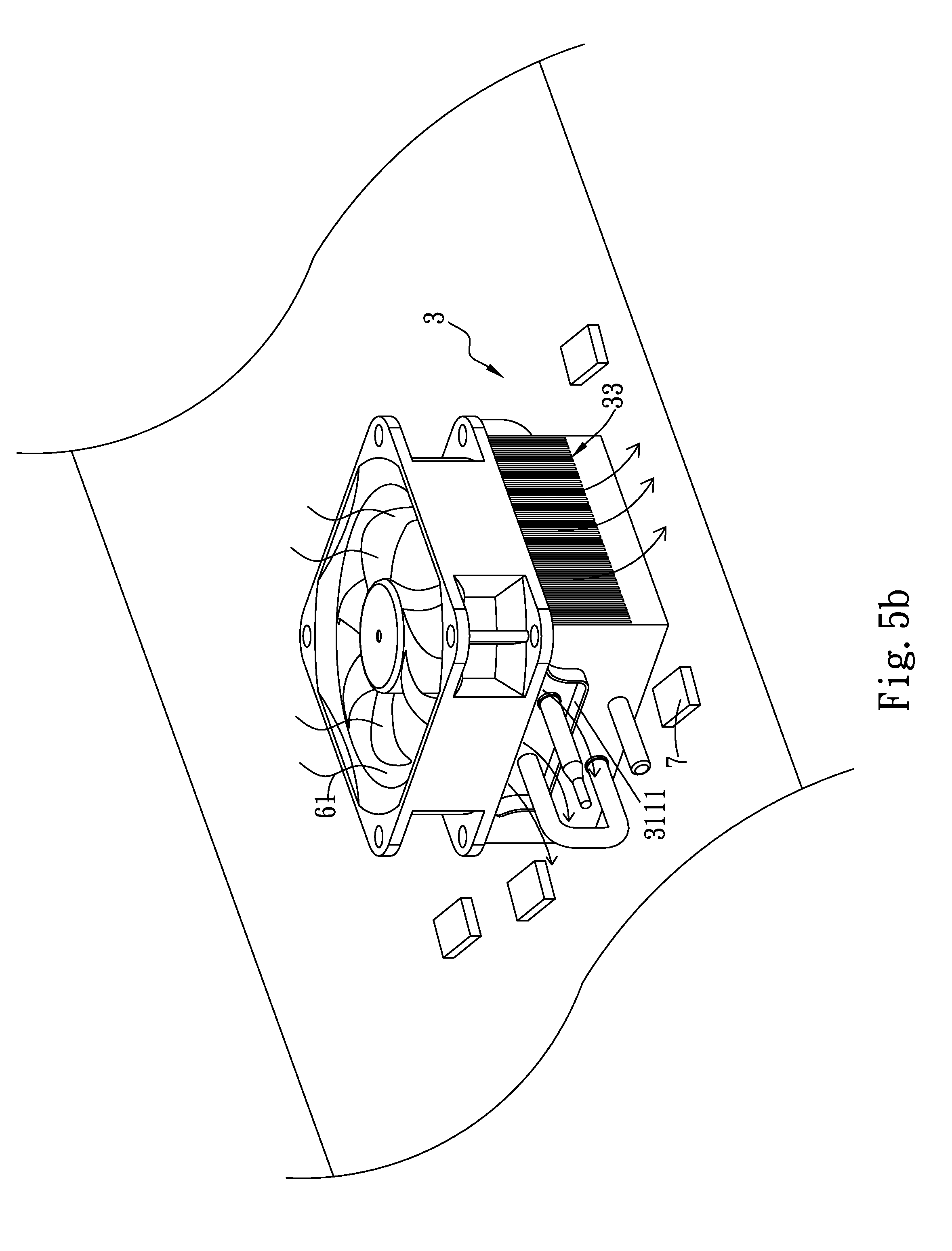
[0022] FIG. 5b is a perspective assembled view of the second embodiment of the thermal module of the present invention; and
[0023] FIG. 5c is a right view of the second embodiment of the thermal module of the present invention.
DETAILED DESCRIPTION OF THE PREFERRED EMBODIMENTS
[0024] Please refer to FIGS. 2a and 2b, in which FIG. 2a is a perspective view of a first embodiment of the heat sink wind guide structure of the present invention and FIG. 2b is a top view thereof. The heat sink wind guide structure includes a heat sink 3 having multiple radiating fins 31 and a wind incoming side 32. Each two adjacent radiating fins 31 define therebetween a heat dissipation flow way 33 in communication with the wind incoming side 32. The radiating fins 31 include a first radiating fin 311 and a second radiating fin 312, which are respectively positioned on two opposite outer sides of the heat sink 3. The first radiating fin 311 has a first extension end 3111 protruding from the first radiating fin 311. The second radiating fin 312 has a second extension end 3121 protruding from the second radiating fin 312.
[0025] In this embodiment, the heat sink 3 is composed of multiple radiating fins 31, which are piled up.
[0026] Please refer to FIGS. 3a and 3b, in which FIG. 3a is a perspective view of a second embodiment of the heat sink wind guide structure of the present invention and FIG. 3b is a top view thereof. The heat sink 3 of the second embodiment is identical to that of the first embodiment in structure and relationship between the respective components and thus will not be repeatedly described. The second embodiment is only different from the first embodiment in that the heat sink 3 of the second embodiment is an extruded aluminum heat sink 3.
[0027] Further referring to FIGS. 2a, 2b, 3a, 3b, a first wind guide wing 3112 and a second wind guide wing 3113 are respectively connected to two sides of the first extension end 3111. The first extension end 3111 and the first and second wind guide wings 3112, 3113 together define a first wind guide passageway 34. A third wind guide wing 3122 and a fourth wind guide wing 3123 are respectively connected to two sides of the second extension end 3121. The second extension end 3121 and the third and fourth wind guide wings 3122, 3123 together define a second wind guide passageway 35.
[0028] Please refer to FIGS. 4a, 4b and 4c, in which FIG. 4a is a perspective exploded view of a first embodiment of the thermal module of the present invention, FIG. 4b is a perspective assembled view of the first embodiment of the thermal module of the present invention and FIG. 4c is a right view thereof. In this embodiment, the thermal module 4 includes a heat sink 3, at least one heat pipe 5 and a fan 6.
[0029] The heat sink 3 has multiple radiating fins 31 and a wind incoming side 32. Each two adjacent radiating fins 31 define therebetween a heat dissipation flow way 33 in communication with the wind incoming side 32. The radiating fins 31 include a first radiating fin 311 and a second radiating fin 312, which are respectively positioned on two opposite outer sides of the heat sink 3. The first radiating fin 311 has a first extension end 3111 protruding from the first radiating fin 311. The second radiating fin 312 has a second extension end 3121 protruding from the second radiating fin 312.
[0030] The heat pipe 5 extends through the heat sink 3. The heat sink 3 has a heat absorption section 36 and a heat dissipation section 37. Two ends of the heat pipe 3 respectively pass through the heat absorption section 36 and heat dissipation section 37 of the heat sink 3.
[0031] The fan 6 is correspondingly mated with the wind incoming side 32 of the heat sink 3 to forcedly guide airflow 61 for dissipating heat from the heat sink 3.
[0032] In this embodiment, the heat sink 3 is composed of multiple radiating fins 31, which are piled up.
[0033] Please refer to FIGS. 5a, 5b and 5c, in which FIG. 5a is a perspective exploded view of a second embodiment of the thermal module of the present invention, FIG. 5b is a perspective assembled view of the second embodiment of the thermal module of the present invention and FIG. 5c is a right view thereof. The thermal module 4 of the second embodiment is identical to that of the first embodiment in structure and relationship between the respective components and thus will not be repeatedly described. The second embodiment is only different from the first embodiment in that the heat sink 3 of the second embodiment is an extruded aluminum heat sink 3.
[0034] Further referring to FIGS. 4a, 4b, 4c, 5a, 5b and 5c, a first wind guide wing 3112 and a second wind guide wing 3113 are respectively connected to two sides of the first extension end 3111. The first extension end 3111 and the first and second wind guide wings 3112, 3113 together define a first wind guide passageway 34 (as shown in FIG. 2b). A third wind guide wing 3122 and a fourth wind guide wing 3123 are respectively connected to two sides of the second extension end 3121. The second extension end 3121 and the third and fourth wind guide wings 3122, 3123 together define a second wind guide passageway 35 (as shown in FIG. 3b).
[0035] The fan 6 serves to forcedly guide the heat dissipation airflow 61 to dissipate heat from the heat sink 3 and the heat pipe 5. The heat dissipation airflow 61 goes from the wind incoming side 32 of the heat sink 3 into the heat sink 3. Then the heat dissipation airflow 61 goes through the heat dissipation flow ways 33 and is exhausted from the heat sink 3. The first and second extension ends 3111, 3112 on the opposite sides of the heat sink 3 serve to guide the heat dissipation airflow 61 toward two other sides of the heat sink 3. In this case, the heat generated by the heat-generating units 7 arranged around the heat sink 3 can be dissipated at the same time. Accordingly, the heat dissipation airflow 61 can be exhausted from many sides of the heat sink 3 to dissipate the heat of many heat-generating units 7 at the same time.
[0036] The above embodiments are only used to illustrate the present invention, not intended to limit the scope thereof. It is understood that many changes and modifications of the above embodiments can be made without departing from the spirit of the present invention. The scope of the present invention is limited only by the appended claims.
* * * * *
D00000
D00001
D00002
D00003
D00004
D00005
D00006
D00007
D00008
D00009
D00010
D00011
XML
uspto.report is an independent third-party trademark research tool that is not affiliated, endorsed, or sponsored by the United States Patent and Trademark Office (USPTO) or any other governmental organization. The information provided by uspto.report is based on publicly available data at the time of writing and is intended for informational purposes only.
While we strive to provide accurate and up-to-date information, we do not guarantee the accuracy, completeness, reliability, or suitability of the information displayed on this site. The use of this site is at your own risk. Any reliance you place on such information is therefore strictly at your own risk.
All official trademark data, including owner information, should be verified by visiting the official USPTO website at www.uspto.gov. This site is not intended to replace professional legal advice and should not be used as a substitute for consulting with a legal professional who is knowledgeable about trademark law.