Contoured Metallic Casting Core
Snyder; Daniel A. ; et al.
U.S. patent application number 12/823165 was filed with the patent office on 2011-12-29 for contoured metallic casting core. This patent application is currently assigned to UNITED TECHNOLOGIES CORPORATION. Invention is credited to Amanda J. Learned, Keith A. Santeler, Daniel A. Snyder.
| Application Number | 20110315336 12/823165 |
| Document ID | / |
| Family ID | 44501655 |
| Filed Date | 2011-12-29 |


| United States Patent Application | 20110315336 |
| Kind Code | A1 |
| Snyder; Daniel A. ; et al. | December 29, 2011 |
Contoured Metallic Casting Core
Abstract
A method for manufacturing an investment casting core uses a metallic blank having a thickness between parallel first and second faces less than a width and length transverse thereto. The blank is locally thinned from at least one of the first and second faces. The local thinning forms a taper on a leading portion of the RMC. The blank is through-cut across the thickness. The blank is inserted into the leading portion into a slot in a pre-formed ceramic core.
| Inventors: | Snyder; Daniel A.; (Manchester, CT) ; Santeler; Keith A.; (Clifton Heights, PA) ; Learned; Amanda J.; (Manchester, CT) |
| Assignee: | UNITED TECHNOLOGIES
CORPORATION Hartford CT |
| Family ID: | 44501655 |
| Appl. No.: | 12/823165 |
| Filed: | June 25, 2010 |
| Current U.S. Class: | 164/23 ; 164/271; 164/6 |
| Current CPC Class: | B22C 9/24 20130101; B22C 9/10 20130101; B22C 9/103 20130101 |
| Class at Publication: | 164/23 ; 164/6; 164/271 |
| International Class: | B22D 25/00 20060101 B22D025/00; B22C 9/10 20060101 B22C009/10; B22C 9/02 20060101 B22C009/02 |
Goverment Interests
US GOVERNMENT RIGHTS
[0001] The invention was made with US Government support under contract W911W6-08-2-0001 awarded by the US Army. The US Government has certain rights in the invention.
Claims
1. A method for manufacturing an investment casting core from a metallic blank having a thickness between parallel first and second faces less than a width and length transverse thereto, the method comprising: locally thinning the blank from at least one of the first and second faces, the local thinning forming a taper on a leading portion of the RMC; through-cutting the blank across the thickness; and inserting the leading portion into a slot in a pre-formed ceramic core.
2. The method of claim 1 wherein: at least the through-cutting comprises at least one of stamping, laser cutting, liquid jet cutting, and EDM.
3. The method of claim 1 wherein: at least the locally thinning comprises at least one of EDM, ECM, MDP, and mechanical machining.
4. The method of claim 1 wherein: the through-cutting and the locally thinning are performed separately.
5. The method of claim 1 wherein: the through-cutting comprises forming a plurality of through-apertures.
6. The method of claim 1 wherein: the locally thinning comprises machining a main portion and leaving a thicker portion downstream of the main portion.
7. The method of claim 1 further comprising: coating the core.
8. The method of claim 1 wherein: the locally thinning comprises forming the taper by thinning both of the first and second faces.
9. The method of claim 8 wherein: the local thinning comprises essentially uniformly removing material from a pressure side along the taper and an intermediate portion downstream thereof and, along the suction side, removing material only from the leading portion.
10. The method of claim 1 wherein: the through-cutting forms apertures within the blank.
11. A method for investment casting comprising: forming according to claim 1 an investment casting core; molding a pattern-forming material at least partially over the at least one investment casting core for forming a pattern; shelling the pattern; removing the pattern-forming material from the shelled pattern for forming a shell; introducing molten alloy to the shell; and removing the shell.
12. The method of claim 11 used to form a gas turbine engine component.
13. The method of claim 11 used to form a gas turbine engine airfoil wherein the core forms a trailing edge outlet slot.
14. An investment casting core comprising: a metallic casting core element having: a tapered leading portion; an intermediate portion downstream of the tapered leading portion; and a trailing portion downstream of the intermediate portion and thicker than the intermediate portion; and a ceramic casting core having a slot receiving the leading portion.
15. The investment casting core of claim 14 wherein: along the leading portion and intermediate portion, a pressure side surface has essentially continuous concave curvature; and along a suction side surface, the intermediate portion has essentially continuous convex curvature and the leading portion has discontinuous curvature so as to provide the taper.
Description
BACKGROUND
[0002] The disclosure relates to investment casting. More particularly, it relates to the investment casting of superalloy turbine engine components.
[0003] Investment casting is a commonly used technique for forming metallic components having complex geometries, especially hollow components, and is used in the fabrication of superalloy gas turbine engine components. The disclosure is described in respect to the production of particular superalloy castings, however it is understood that the disclosure is not so limited.
[0004] Gas turbine engines are widely used in aircraft propulsion, electric power generation, and ship propulsion. In gas turbine engine applications, efficiency is a prime objective. Improved gas turbine engine efficiency can be obtained by operating at higher temperatures, however current operating temperatures in the turbine section exceed the melting points of the superalloy materials used in turbine components. Consequently, it is a general practice to provide air cooling. Cooling is provided by flowing relatively cool air from the compressor section of the engine through passages in the turbine components to be cooled. Such cooling comes with an associated cost in engine efficiency. Consequently, there is a strong desire to provide enhanced specific cooling, maximizing the amount of cooling benefit obtained from a given amount of cooling air. This may be obtained by the use of fine, precisely located, cooling passageway sections.
[0005] The cooling passageway sections may be cast over casting cores. Ceramic casting cores may be formed by molding a mixture of ceramic powder and binder material by injecting the mixture into hardened steel dies. After removal from the dies, the green cores are thermally post-processed to remove the binder and fired to sinter the ceramic powder together. The trend toward finer cooling features has taxed core manufacturing techniques. The fine features may be difficult to manufacture and/or, once manufactured, may prove fragile. Commonly-assigned U.S. Pat. Nos. 6,637,500 of Shah et al. and 6,929,054 of Beals et al and Pre-grant Publication 2007/261814 of Luczak (the disclosures of which are incorporated by reference herein as if set forth at length) disclose use of ceramic and refractory metal core combinations.
[0006] FIG. 1 shows a trailing edge portion of a turbine airfoil 20 as cast within a shell 22. For casting the internal passageways, the shell contains a core assembly. The exemplary core assembly includes a ceramic feed core having spanwise legs 30, 32, and 34 for casting associated passageway legs. The leg 34 casts a trailing spanwise passageway 36. The core assembly also includes metallic cores, of which cores 40, 42, and 44 are shown. The exemplary metallic cores are formed of refractory metal sheet stock. The core 40 forms a pressure side outlet circuit, the core 42 forms a suction side outlet circuit, and the core 44 forms a trailing edge outlet slot 50. The outlet slot 50 is fed from the passageway 36. During core assembly, a leading portion of the core 44 is secured within a mating slot of the trailing leg 34 of the ceramic core.
SUMMARY
[0007] One aspect of the disclosure involves a method for manufacturing an investment casting core from a metallic blank. The blank has a thickness between parallel first and second faces less than a width and length transverse thereto. The blank is locally thinned from at least one of the first and second faces. The blank is through-cut across the thickness. The blank is inserted into the leading portion into a slot in a pre-formed ceramic core.
[0008] In various implementations, through-cutting may comprise at least one of laser cutting, liquid jet cutting, and EDM. The thinning may comprise at least one of EDM, ECM, MDP, and mechanical machining.
[0009] In an investment casting method, the investment casting core may be at least partially overmolded by a pattern-forming material for forming a pattern. The pattern may be shelled. The pattern-forming material may be removed from the shelled pattern for forming a shell. Molten alloy may be introduced to the shell. The shell may be removed. The method may be used to form a gas turbine engine component. An exemplary component is an airfoil wherein the core forms trailing edge outlet passageways.
[0010] Another aspect of the disclosure involves an investment casting core having a metallic core element and a ceramic core. The metallic core element has a tapered leading portion, an intermediate portion downstream of the tapered leading portion, and a trailing portion downstream of the intermediate portion and thicker than the intermediate portion. The ceramic casting core has a slot receiving the leading portion.
[0011] The details of one or more embodiments are set forth in the accompanying drawings and the description below. Other features, objects, and advantages will be apparent from the description and drawings, and from the claims.
BRIEF DESCRIPTION OF THE DRAWINGS
[0012] FIG. 1 is a partial streamwise sectional view of a trailing edge portion of a prior art airfoil cast within a ceramic shell.
[0013] FIG. 2 is a partial streamwise sectional view of a modified airfoil.
[0014] FIG. 2A is an enlarged view of a portion of FIG. 2.
[0015] FIG. 3 is a partially schematic/simplified view of a pattern including the core assembly.
[0016] FIG. 4 is a partially schematic/simplified view of a blade cast in a shell formed over the pattern.
[0017] FIG. 5 is an enlarged partial pressure side view of a discharge slot of the blade of FIG. 4.
[0018] FIG. 6 is a flowchart of a core manufacture process.
[0019] Like reference numbers and designations in the various drawings indicate like elements.
DETAILED DESCRIPTION
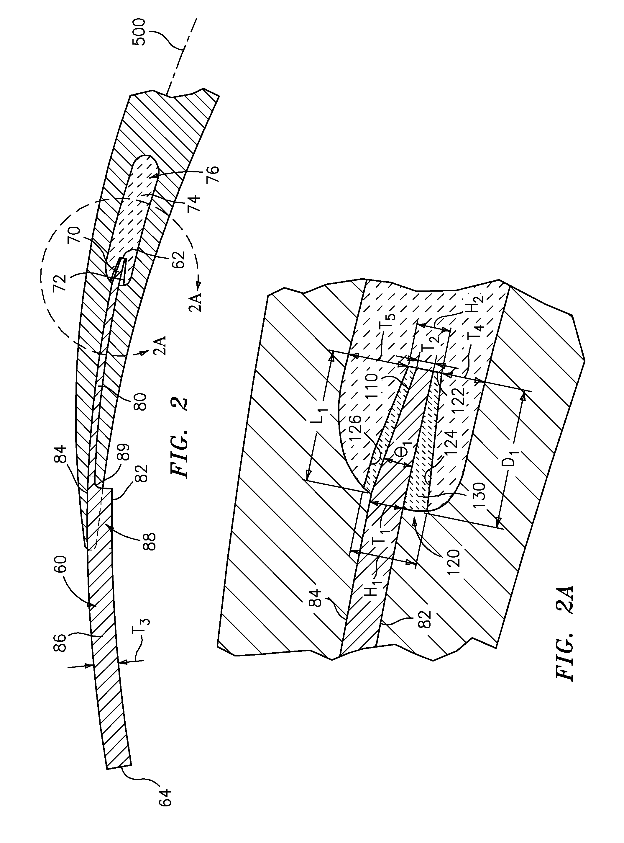
[0020] FIG. 2 shows an alternative refractory metal core 60 which has a leading/upstream edge/end 62 and a trailing/downstream edge/end 64. The exploded view of FIG. 3 shows an inboard end 66 and an outboard end 68. As is discussed further below, an upstream-most portion 70 extending aft from the leading edge/end 62 is configured to be received within and mate with a trailing slot 72 of a trailing leg 74 of a ceramic feedcore 76. The RMC 60 has an intermediate portion 80 which casts the majority of the ultimate trailing edge discharge slot. In the exemplary RMC 60, along this region 80, the RMC pressure side/surface 82 and suction side/surface 84 are separated by an essentially constant RMC thickness T.sub.1 (FIG. 2A). Downstream of the portion 80, the exemplary RMC thickens. A relatively thick portion 86 having an essentially constant thickness shown as T.sub.3 extends to the trailing end/edge 64. Of this portion 86, a smaller upstream portion 88 casts pressure side discharge openings in the airfoil.
[0021] FIG. 3 (a partially schematic/simplified view of a pattern) shows the portion 80 having holes 100 for casting posts within the slot. FIG. 3 further shows the portion 88 as having streamwise elongate tapering holes 102 which are interspersed with intact portions 104. The intact portions 104 cast pressure side openings from the trailing edge discharge slot; whereas the holes 102 cast walls therebetween.
[0022] In the exemplary core assembly, the feedcore slot 72 and RMC portion 70 both have an upstream-ward taper. The exemplary thickness T.sub.2 of the RMC at the leading edge is less than T.sub.1 (e.g., 30-60%). The exemplary RMC taper is essentially constant at an angle of .theta..sub.1 over a streamwise length L.sub.1. The exemplary taper is provided by relieving/beveling only one of the two faces 82 and 84 (the face 84 in the exemplary embodiment with a bevel facet/surface 110). The exemplary relief provides the taper angle .theta..sub.1. Exemplary .theta..sub.1 are 0.1-3.0.degree., more narrowly 1.0-2.5.degree.. Exemplary taper length L.sub.1 is coincident with or slightly less than a depth D.sub.1 of the slot. The exemplary slot has an opening 120 having a height H.sub.1 which may be greater than T.sub.1 and has a base 122 with a height H.sub.2 which is greater than T.sub.2. A portion of the slot between respective slot walls 124 and 126 and the RMC may be filled with an adhesive or slurry 130. The exemplary streamwise cross-section of the RMC is shown as generally arcuate with concavity along the pressure side and convexity along the suction side so as to correspond to a median of the airfoil cross-section.
[0023] Exemplary L.sub.1 is 0.040-0.100 inch (1-2.5 mm), more narrowly 0.050-0.075 inch (1.3 mm-9 mm). Exemplary T.sub.1 is 0.012 inch (0.3 mm), more broadly 0.005-0.020 inch (0.13-0.5 mm) or 0.010-0.015 inch (0.25-0.38 mm). Exemplary T.sub.2 is 0.005 inch (0.13 mm), more broadly 0.002-0.015 inch (0.05-0.38 mm) or 0.003-0.007 inch (0.08-0.18 mm) or 25-75% of T.sub.1, more narrowly, 40-60%. Exemplary T.sub.3 is 0.035 inch (0.9 mm), more broadly 0.020-0.050 inch (0.5-1.3 mm) or 200-500% of T.sub.1, more narrowly 250-400%. Exemplary feedcore thickness at either side of the slot base 122 (shown as T.sub.4 to the pressure side and T.sub.5 to the suction side) may be at least 0.018 inch (0.46 mm), more narrowly 0.018-0.040 inch (0.46-1.0 mm) or 0.08-0.025 inch (0.46-0.64 mm).
[0024] In an exemplary sequence 200 of manufacture (FIG. 6), the RMC 84 may be machined from a strip having a thickness equal to T.sub.3, a greater width, and a yet greater length. In an initial stage of manufacture, gross thickness features may be machined 202 to provide the thickness T.sub.1 of the intermediate portion and provide the bevel/taper. Specifically, the exemplary machining is from the pressure side face 82 to define the intermediate portion and from the suction side face 84 to provide the taper of the leading portion. However, the step 202 may easily be further divided. Exemplary machining may be mechanical machining or may be an abrasive grinding, electrodischarge machining (EDM), electrochemical machining (ECM), or a molecular decomposition process (MDP).
[0025] Additionally, a series of through-cuts are cut 206 to define the holes/apertures 100 for forming posts 150 (FIG. 4) within the outlet slot and holes/apertures 102 for forming trailing dividing walls 152 along the slot outlet 154 at the trailing edge 156. FIG. 4 further shows: the airfoil 160 having a leading edge 162 and a tip 164; the platform 170 at the inboard end of the aitrfoil; and the firtree attachment root 172 depending from the underside of the platform. The root has the inlet ports 174 to the trunks of the cooling passageway network (cast over the ceramic feedcore trunks). FIG. 5 shows the outlet 154 as including a spanwise array of segments/portions/openings 180 along the airfoil pressure side between associated pairs of the dividing walls 152. As is discussed above, the openings 180 are cast by the intact portions 104 of the RMC portion 88 of FIG. 2. A curving transition 89 (FIG. 2) between the RMC portions 80 and 86/88 casts a curving transition 182 (FIG. 5) between a main portion 184 of the slot and the openings 180.
[0026] Exemplary cutting may be via a punching/stamping operation or, alternatively, mechanical drilling, laser cutting, liquid jet cutting, and/or EDM. To provide the RMC in the desired arcuate shape corresponding to the airfoil median 500, the RMC is bent 208 (e.g., via stamping). This bending may also form a spanwise variation (e.g., to accommodate a varying relationship in the position of the feedcore relative to the discharge slot) such as creating a net spanwise twist. An exemplary stamping is performed via one or more pressing stages in custom presses having opposing die faces contoured to mate with the RMC. The RMC may be coated 210 with a protective coating. Alternatively a coating could be applied pre-assembly. Suitable coating materials include silica, alumina, zirconia, chromia, mullite and hafnia. Preferably, the coefficient of thermal expansion (CTE) of the refractory metal and the coating are similar. Coatings may be applied by any appropriate line-of-sight or non-line-of sight technique (e.g., chemical or physical vapor deposition (CVD, PVD) methods, plasma spray methods, electrophoresis, and sol gel methods). Individual layers may typically be 0.1 to 1 mil thick. Layers of Pt, other noble metals, Cr, Si, W, and/or Al, or other non-metallic materials may be applied to the metallic core elements for oxidation protection in combination with a ceramic coating for protection from molten metal erosion and dissolution.
[0027] The ceramic core may be (e.g., silica-, zircon-, or alumina-based) molded 212. The as-molded ceramic material may include a binder. The binder may function to maintain integrity of the molded ceramic material in an unfired green state. Exemplary binders are wax-based. After the molding 212, the preliminary core assembly may be debindered/fired 214 to harden the ceramic (e.g., by heating in an inert atmosphere or vacuum). The slot 72 may have been formed as part of the molding 212 or may be cut in the ceramic (e.g., in the green state or in the fired state). The RMC may be inserted 216 into the ceramic core to assemble and an adhesive or slurry introduced 218.
[0028] FIG. 6 shows an exemplary method 220 for investment casting using the core assembly. Other methods are possible, including a variety of prior art methods and yet-developed methods. The fired core assembly is then overmolded 230 with an easily sacrificed material such as a natural or synthetic wax (e.g., via placing the assembly in a mold and molding the wax around it). There may be multiple such assemblies involved in a given mold.
[0029] The overmolded core assembly (or group of assemblies) forms a casting pattern with an exterior shape largely corresponding to the exterior shape of the part to be cast. The pattern may then be assembled 232 to a shelling fixture (e.g., via wax welding between end plates of the fixture). The pattern may then be shelled 234 (e.g., via one or more stages of slurry dipping, slurry spraying, or the like). After the shell is built up, it may be dried 236. The drying provides the shell with at least sufficient strength or other physical integrity properties to permit subsequent processing. For example, the shell containing the invested core assembly may be disassembled 238 fully or partially from the shelling fixture and then transferred 240 to a dewaxer (e.g., a steam autoclave). In the dewaxer, a steam dewax process 242 removes a major portion of the wax leaving the core assembly secured within the shell. The shell and core assembly will largely form the ultimate mold. However, the dewax process typically leaves a wax or byproduct hydrocarbon residue on the shell interior and core assembly.
[0030] After the dewax, the shell is transferred 244 to a furnace (e.g., containing air or other oxidizing atmosphere) in which it is heated 246 to strengthen the shell and remove any remaining wax residue (e.g., by vaporization) and/or converting hydrocarbon residue to carbon. Oxygen in the atmosphere reacts with the carbon to form carbon dioxide. Removal of the carbon is advantageous to reduce or eliminate the formation of detrimental carbides in the metal casting. Removing carbon offers the additional advantage of reducing the potential for clogging the vacuum pumps used in subsequent stages of operation.
[0031] The mold may be removed from the atmospheric furnace, allowed to cool, and inspected 248. The mold may be seeded 250 by placing a metallic seed in the mold to establish the ultimate crystal structure of a directionally solidified (DS) casting or a single-crystal (SX) casting. Nevertheless the present teachings may be applied to other DS and SX casting techniques (e.g., wherein the shell geometry defines a grain selector) or to casting of other microstructures. The mold may be transferred 252 to a casting furnace (e.g., placed atop a chill plate in the furnace). The casting furnace may be pumped down to vacuum 254 or charged with a non-oxidizing atmosphere (e.g., inert gas) to prevent oxidation of the casting alloy. The casting furnace is heated 256 to preheat the mold. This preheating serves two purposes: to further harden and strengthen the shell; and to preheat the shell for the introduction of molten alloy to prevent thermal shock and premature solidification of the alloy.
[0032] After preheating and while still under vacuum conditions, the molten alloy is poured 258 into the mold and the mold is allowed to cool to solidify 260 the alloy (e.g., after withdrawal from the furnace hot zone). After solidification, the vacuum may be broken 262 and the chilled mold removed 264 from the casting furnace. The shell may be removed in a deshelling process 266 (e.g., mechanical breaking of the shell).
[0033] The core assembly is removed in a decoring process 268 to leave a cast article (e.g., a metallic precursor of the ultimate part). The cast article may be machined 270, chemically and/or thermally treated 272 and coated 274 to form the ultimate part. Some or all of any machining or chemical or thermal treatment may be performed before the decoring.
[0034] One or more embodiments have been described. Nevertheless, it will be understood that various modifications may be made. For example, the principles may be implemented using modifications of various existing or yet-developed processes, apparatus, or resulting cast article structures (e.g., in a reengineering of a baseline cast article to modify cooling passageway configuration). In any such implementation, details of the baseline process, apparatus, or article may influence details of the particular implementation. Accordingly, other embodiments are within the scope of the following claims.
* * * * *
D00000
D00001
D00002
D00003
D00004
D00005
D00006
XML
uspto.report is an independent third-party trademark research tool that is not affiliated, endorsed, or sponsored by the United States Patent and Trademark Office (USPTO) or any other governmental organization. The information provided by uspto.report is based on publicly available data at the time of writing and is intended for informational purposes only.
While we strive to provide accurate and up-to-date information, we do not guarantee the accuracy, completeness, reliability, or suitability of the information displayed on this site. The use of this site is at your own risk. Any reliance you place on such information is therefore strictly at your own risk.
All official trademark data, including owner information, should be verified by visiting the official USPTO website at www.uspto.gov. This site is not intended to replace professional legal advice and should not be used as a substitute for consulting with a legal professional who is knowledgeable about trademark law.