Embroidery Fabric Clamping Unit For Use With Embroidery Machine And Embroidery Machine Comprising Same
Lee; Tae-Hoon ; et al.
U.S. patent application number 13/141051 was filed with the patent office on 2011-12-29 for embroidery fabric clamping unit for use with embroidery machine and embroidery machine comprising same. Invention is credited to Kyung-Min Kim, Tae-Hoon Lee.
| Application Number | 20110315059 13/141051 |
| Document ID | / |
| Family ID | 42281758 |
| Filed Date | 2011-12-29 |


| United States Patent Application | 20110315059 |
| Kind Code | A1 |
| Lee; Tae-Hoon ; et al. | December 29, 2011 |
EMBROIDERY FABRIC CLAMPING UNIT FOR USE WITH EMBROIDERY MACHINE AND EMBROIDERY MACHINE COMPRISING SAME
Abstract
Disclosed are an embroidery fabric clamping unit for use with an embroidery machine, and an embroidery machine comprising the same, which allow the embroidering of even embroidery fabrics of arbitrary shape. The embroidery fabric clamping unit comprises: a unit body having a joining part provided for attachment to and detachment from a work table of the embroidery machine; an embroidery fabric support table which is linked to the unit body and supports the embroidery fabric to be embroidered by the embroidery machine; a lever which is supported on the unit body, with the embroidery fabric placed in between, and is able to apply pressure to and release pressure from the embroidery fabric support table; and a lever driving part for driving the lever.
| Inventors: | Lee; Tae-Hoon; (Seoul, KR) ; Kim; Kyung-Min; (Seoul, KR) |
| Family ID: | 42281758 |
| Appl. No.: | 13/141051 |
| Filed: | March 5, 2010 |
| PCT Filed: | March 5, 2010 |
| PCT NO: | PCT/KR2010/001383 |
| 371 Date: | June 20, 2011 |
| Current U.S. Class: | 112/103 |
| Current CPC Class: | D05C 9/04 20130101; D05B 35/02 20130101; D05B 39/00 20130101; D05B 31/00 20130101 |
| Class at Publication: | 112/103 |
| International Class: | D05C 9/04 20060101 D05C009/04; D05B 35/00 20060101 D05B035/00 |
Foreign Application Data
| Date | Code | Application Number |
|---|---|---|
| Mar 6, 2009 | KR | 10-2009-0019199 |
Claims
1. An embroidery fabric clamping unit for an embroidery machine, comprising: a unit body comprising a joining part detachably disposed on a work table of the embroidery machine; one or more embroidery fabric support tables each coupled to the unit body and supporting an embroidery fabric to be embroidered by the embroidery machine; one or more levers each supported by the unit body and applying a pressure to a corresponding embroidery fabric support table or releasing the pressure from the corresponding embroider fabric support table across the embroidery fabric; and a lever driving part driving the one or more levers.
2. The embroidery fabric clamping unit of claim 1, wherein at least one of the one or more embroidery fabric support tables and the one or more levers are provided in plurality.
3. The embroidery fabric clamping unit of claim 2, wherein at least one of the one or more embroidery fabric support tables and the one or more levers are provided so that the gaps therebetween are adjustable.
4. The embroidery fabric clamping unit of claims 1, wherein the unit body includes a lever support part supporting the one or more levers and detachably coupled to the unit body.
5. The embroidery fabric clamping unit of claim 4, wherein the one or more levers are detachably coupled to the lever support part.
6. The embroidery fabric clamping unit of claims 1, wherein the one or more levers comprise an elastic material.
7. The embroidery fabric clamping unit of claims 1, wherein each of the one or more levers pivotaly move between a clamping position where the embroidery fabric is clamped by pressing the corresponding embroidery fabric on the corresponding embroidery fabric support tables and a release position where the embroidery fabric is unclamped by being spaced from the clamping position.
8. The embroidery fabric clamping unit of claim 7, wherein the lever driving part includes: a pneumatic cylinder; a piston supported by the pneumatic cylinder and selectively applying a pressure to the one or more levers; and a foot switch selectively supplying air to the pneumatic cylinder.
9. The embroidery fabric clamping unit of claim 7, wherein the lever driving part may further comprise an elastic member allowing the one or more levers to be elastically biased to the release position.
10. An embroidery machine, comprising: a work table on which a raw fabric to be embroidered or an embroidery fabric is disposed; an embroidery fabric clamping unit according to claim 1 detachably mounted on the work table; a raw fabric setting frame for setting the raw fabric; and a needle embroidering the embroidery fabric clamped by the embroidery fabric clamping unit.
11. The embroidery fabric clamping unit of claim 2, wherein the unit body includes a lever support part supporting the one or more levers and detachably coupled to the unit body.
12. The embroidery fabric clamping unit of claim 11, wherein the one or more levers are detachably coupled to the lever support part.
13. The embroidery fabric clamping unit of claim 3, wherein the unit body includes a lever support part supporting the one or more levers and detachably coupled to the unit body.
14. The embroidery fabric clamping unit of claim 13, wherein the one or more levers are detachably coupled to the lever support part.
15. The embroidery fabric clamping unit of claim 2, wherein the one or more levers comprise an elastic material.
16. The embroidery fabric clamping unit of claim 3, wherein the one or more levers comprise an elastic material.
17. The embroidery fabric clamping unit of claim 2, wherein each of the one or more levers pivotaly move between a clamping position where the embroidery fabric is clamped by pressing the corresponding embroidery fabric on the corresponding embroidery fabric support tables and a release position where the embroidery fabric is unclamped by being spaced from the clamping position.
18. The embroidery fabric clamping unit of claim 3, wherein each of the one or more levers pivotaly move between a clamping position where the embroidery fabric is clamped by pressing the corresponding embroidery fabric on the corresponding embroidery fabric support tables and a release position where the embroidery fabric is unclamped by being spaced from the clamping position.
19. An embroidery machine, comprising: a work table on which a raw fabric to be embroidered or an embroidery fabric is disposed; an embroidery fabric clamping unit according to claim 2 detachably mounted on the work table; a raw fabric setting frame for setting the raw fabric; and a needle embroidering the embroidery fabric clamped by the embroidery fabric clamping unit.
20. An embroidery machine, comprising: a work table on which a raw fabric to be embroidered or an embroidery fabric is disposed; an embroidery fabric clamping unit according to claim 3 detachably mounted on the work table; a raw fabric setting frame for setting the raw fabric; and a needle embroidering the embroidery fabric clamped by the embroidery fabric clamping unit.
Description
TECHNICAL FIELD
[0001] The present invention relates to an embroidery fabric clamping unit for an embroidery machine and an embroidery machine including the same, and more particularly, to an embroidery fabric clamping unit for an embroidery machine and an embroidery machine including the same which enable embroidering of embroidery fabrics having an arbitrary shape.
BACKGROUND ART
[0002] An embroidery machine is an apparatus that automatically embroiders various patterns such as characters, figures, and images on raw fabrics using various colors of yarns. Embroidery machines are classified into single needle machines and multi needle machines according to the number of needles mounted thereon.
[0003] Embroidery machines include an embroidery frame for setting embroidery fabrics such as raw fabrics. Korea Patent Publication No. 10-2004-91598 discloses an embroidery frame for setting a raw fabric which can prevent deformation of the embroidery frame.
[0004] However, since the disclosed embroidery frame is one for setting a fabric itself, it is difficult to set ready-made-products such as shoes, bags, pants, and T-shirts whose sewing has been already completed. The reason is because a typical embroidery frame has a structure in which ready-made-products such as shoes could not be properly fixed because it is configured to clamp four edges of a raw fabric.
DETAILED DESCRIPTION
Technical Problems
[0005] It is thus an object of the present invention to provide an embroidery fabric clamping unit for an embroidery machine and an embroidery machine including the same which enables embroidering of embroidery fabrics of arbitrary shape.
Technical Solutions
[0006] The above object can be achieved by embroidery fabric clamping units for an embroidery machine which includes: a unit body including a joining part detachably disposed on a work table of the embroidery machine; one or more embroidery fabric support tables each coupled to the unit body and supporting an embroidery fabric to be embroidered by the embroidery machine; one or more levers each supported by the unit body and applying a pressure to a corresponding embroidery fabric support table or releasing the pressure from the corresponding embroider fabric support table across the embroidery fabric; and a lever driving part driving the one or more levers. Here, at least one of the one or more embroidery fabric support tables and the one or more levers are provided in plurality. Also, at least one of the one or more embroidery fabric support tables and the one or more levers are provided so that the gaps therebetween are adjustable.
[0007] Furthermore, the unit body may include a lever support part supporting the one or more levers and detachably coupled to the unit body.
[0008] Here, the one or more levers may be detachably coupled to the lever support part.
[0009] Furthermore, the one or more levers may comprise an elastic material.
[0010] Also, each of the one or more levers may pivotaly move between a clamping position where the embroidery fabric is clamped by pressing the embroidery fabric on the corresponding embroidery fabric support tables and a release position where the embroidery fabric is unclamped by being spaced from the clamping position.
[0011] Also, the lever driving part may include: a pneumatic cylinder; a piston supported by the pneumatic cylinder and selectively applying a pressure to the one or more levers; and a foot switch selectively supplying air to the pneumatic cylinder.
[0012] Here, the lever driving part may further comprise an elastic member allowing the one or more levers to be elastically biased to the release position.
[0013] The above-mentioned object can be achieved by an embroidery machine which comprises: a work table on which a raw fabric to be embroidered or an embroidery fabric is disposed; an embroidery fabric clamping unit according to any one of claims 1 through 3 detachably mounted on the work table; a raw fabric setting frame for setting the raw fabric; and a needle embroidering the embroidery fabric clamped by the embroidery fabric clamping unit.
Advantageous Effects
[0014] The embroidery fabric clamping unit for an embroidery machine and the embroidery machine including the same provide the following advantages.
[0015] First, since ready-made-products such as shoes and bags can be embroidered through clamping, the usability of an embroidery machine can be enhanced.
[0016] Second, since a gap between levers for clamping embroidery fabrics or embroidery fabric support tables can be adjusted, various shapes of embroidery fabrics can be clamped.
BRIEF DESCRIPTION OF DRAWINGS
[0017] FIG. 1 is a front view illustrating an embroidery machine according to an embodiment of the present invention;
[0018] FIG. 2 is a perspective side view illustrating an embroidery fabric clamping unit of the embroidery machine of FIG. 1;
[0019] FIG. 3 is a perspective plan view illustrating an embroidery fabric clamping unit of the embroidery machine of FIG. 1;
[0020] FIG. 4 is a perspective front view illustrating an embroidery fabric clamping unit of the embroidery machine of FIG. 1;
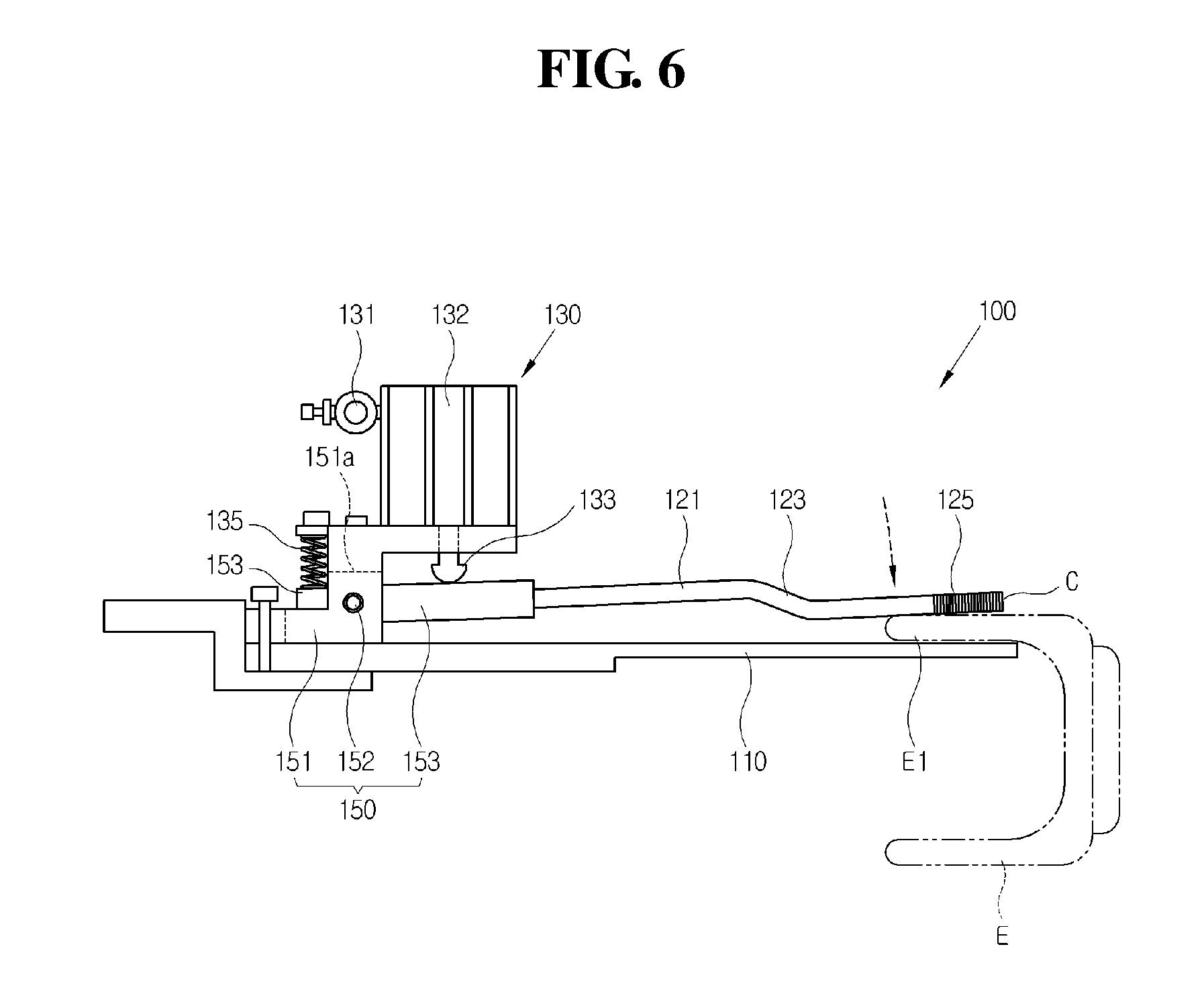
[0021] FIGS. 5 and 6 are views illustrating a clamping process of an embroidery fabric clamping unit of the embroidery machine of FIG. 1;
[0022] FIG. 7 is a plan view illustrating an embroidery fabric clamping unit of a second embodiment of the present invention; and
[0023] FIGS. 8 through 10 are magnified views illustrating an embroidery fabric clamping unit of the embroidery machine of FIG. 1, which is attached with an elastic member.
BEST MODES FOR PRACTICING INVENTION
[0024] Hereinafter, exemplary embodiments of an embroidery fabric clamping unit for an embroidery machine and an embroidery machine including the same will be described in detail with reference to the accompanying drawings.
[0025] Referring to FIG. 1, an embroidery machine 1 includes a work table 10 that enables an embroidering work by moving embroidery fabrics E in the X or Y direction; a needle 20 stitching the embroidery fabrics E; a needle driving part 30 feeding a yarn for stitching and driving the needle 20; a main body 40 supporting the work table 10; and a user input part 50 inputting an embroidery pattern to be embroidered on the embroidery fabric and inputting a control command.
[0026] Sports shoes are exemplified as embroidery fabrics in FIG. 1, and a bobbin wound with a bobbin thread is received in the sports shoes.
[0027] Depending on an embodiment, the user input part 50 may be omitted.
[0028] An embroidery fabric clamping unit 100 for clamping embroidery fabrics such as raw fabrics, shoes, bags, pants, and T-shirts may be detachably coupled to the work table 10.
[0029] If needed, a typical raw fabric setting frame (not shown) may be installed on the work table 10 to clamp a raw fabric at an edge thereof with a rectangular or circular shape. The raw fabric setting frame (not shown) may also be detachably installed on the work table 10.
[0030] As shown in FIGS. 2 through 5, the embroidery fabric clamping unit 100 for the embroidery machine according to the first embodiment of the present invention includes a unit body 140 detachably coupled to the work table 10; an embroidery fabric support table 110 supporting the embroidery fabrics E to be embroidered by the embroidery machine 1; a lever 120 applying a pressure to the embroidery fabric support table 110 or releasing a pressure from the embroidery fabric support table 110 when the embroidery fabrics are disposed therebetween; and a lever driving part 130 driving the lever 120.
[0031] The unit body 140 includes a joining part 143 coupled to the work table 10 and a connection part 145 connected to the embroidery fabric support table 110.
[0032] One or more joining holes 143a are formed in the joining part 143 to allow the joining part 143 to be coupled to the work table 10 by a coupling member (not shown), but embodiments are not limited thereto. For example, the joining part 143 may be coupled to the work table 10 by various coupling methods.
[0033] One or more joining holes 146 are formed in the connection part 145 to allow the connection part 145 to be coupled to the embroidery fabric support table 110.
[0034] Each of the embroidery fabric support table 110 includes a connection end 111 connected to the connection part 145 of the unit body 140 and a contact end 113 contacting the embroidery fabrics E.
[0035] The surface of the contact end 113 is processed to have a surface roughness for a larger contact frictional force against the embroidery fabrics E.
[0036] Each lever 120 is supported by the unit body 140.
[0037] Each lever 120 includes an extension part 121 extending along the longitudinal direction; a bent part 123 bent toward the contact end 113; and a contact part 125 extending from the bent part 123 and facing the contact end 113. The shape of the lever 120 may be modified as long as the lever 120 can clamp the embroidery fabrics E together with the embroidery fabric support table 110.
[0038] As shown in the drawing, the surface of the contact part 125 may be processed to have a surface roughness to generate a larger contact frictional force against the embroidery fabrics E.
[0039] Here, the lever 120 may be formed of a metallic material such as aluminum and stainless steel. The lever 120 may also be formed of an elastic material. The elastic material may include plastic.
[0040] When the lever 120 is formed of a metallic material, the lever 120 may be coated with an elastic material such as rubber, sponge, and plastic.
[0041] The lever driving part 130 may drive the levers 120 using one of driving sources such as pneumatic, hydraulic, and electric motors.
[0042] The unit body 140 may include a lever support part 150 for supporting the levers 120.
[0043] The lever support part 150 may be detachably provided to the unit body 140. The lever support part 150 may be slidably provided to the unit body 140.
[0044] As shown in FIGS. 2 and 4, the lever support part 150 includes a lever insertion part which the lever 120 is inserted into, a lever clamping part 155 for clamping the lever 120 in the lever insertion part 153, and a support body 151 for supporting the lever insertion part 153.
[0045] The lever insertion part 153 may have an insertion hole 153a for receiving the lever 120. The lever 120 inserted into the insertion hole 153a is clamped by the lever clamping part 155 provided on one side of the lever insertion part 153. The lever insertion part 153 may be omitted in certain embodiments. More specifically, as shown throughout the attached drawings, the lever 120 is not coupled to the support body 151 indirectly while it is inserted in the lever insertion part 153, but may be directly coupled to the support body 151 without intervention of the lever insertion part 153.
[0046] The lever 120 may be replaced by unfastening the lever clamping part 155. In other words, the lever 120 is detachably coupled to the lever support part 150.
[0047] The support body 151 may have an opening 151 a for receiving one end of the lever insertion part 153 such that the lever insertion part 153 receiving the lever 120 pivotaly moves between a clamping position C and a release position B that are described later.
[0048] The lever insertion part 153 received in the opening 151 a is pivoted on a hinge 152 in the support body 151.
[0049] Accordingly, as shown in FIGS. 5 and 6, the lever 120 inserted into the lever insertion part 153 may apply a pressure to an embroidery fabric E, and may pivot between the clamping position C where the embroidery fabric is clamped and the release position B where the embroidery fabric is unclamped. The lever 120 may also vertically move instead of pivotaly moving. Also, the lever 120 may vertically slide along a guide rail (not shown). In other words, the lever 120 may slide between the clamping position C where the embroidery fabric is clamped and the release position B where the embroidery fabric is unclamped.
[0050] As shown in FIG. 2, the support body 151 is disposed on the connection end 111 of the embroidery fabric support table 110.
[0051] A coupling hole (not shown) communicating with the joining hole 146 of the unit body 140 is formed in the connection end 111 of the embroidery fabric support table 110. A slot 154 communicating with the joining hole 146 and the coupling hole (not shown) is formed in the support body 151. The unit body 140, the support 110, and the support body 151 are coupled to each other by the coupling member penetrating the joining hole 146, the coupling hole (not shown), and the slot 154.
[0052] Hereinafter, an example of the lever driving part 130 that drives the lever using a pneumatic pressure will be described in detail. As shown in FIGS. 2 through 5, the lever driving part 130 includes a pneumatic cylinder 132 including an air nipple 131, and a piston 133 supported by the pneumatic cylinder 132 and selectively applying a pressure to the lever 120.
[0053] When air is injected through the air nipple 131, the piston 133 downwardly moves to apply a pressure to the lever 120 toward the embroidery fabric support table 110.
[0054] When air injection through the air nipple 131 is interrupted, the piston 133 may enter into an idle state in which a pneumatic pressure is not applied to the lever 120.
[0055] As shown in FIG. 5, the lever driving part 130 may further include an elastic member 135 that restores the lever 120 to the release position B. When air injection is interrupted, the lever 120 may be restored to the release position B.
[0056] As shown in FIG. 2, the elastic member 135 is disposed between an elastic member support piece 134 connected to the support body 151 and the end of the lever insertion part 153 penetrating the opening 151a of the support body 151. The elastic member 135 may apply an elastic force to the lever insertion part 153 to allow the lever 120 to be elastically biased. In certain embodiments, the elastic force may be directly applied to the lever 120.
[0057] Here, the elastic member 135 may be disposed on the opposite side to the piston 133 across the hinge 152. More specifically, the elastic member 135 may apply an elastic force to the end of the lever insertion part 153 such that the contact part 125 of the lever 120 pivots toward the release position B. That is, the elastic force F of the elastic member 135 is applied in the direction of the arrow as shown in FIG. 5.
[0058] In certain embodiments, the elastic member 135 may also be disposed on the side of the piston based on the hinge 152. In this case, the elastic force of the elastic member 135 should be applied in the opposite direction of the elastic force F shown in FIG. 5.
[0059] Also, the lever driving part 130 may further include a switch (not shown) that can selectively supply air through the air nipple 131. The switch (not shown) may be manually or automatically manipulated.
[0060] When a manual manipulation method is adopted, the switch (not shown) may include a mechanical switch.
[0061] The switch (not shown) may be provided as a foot switch (not shown) that is manipulated by a foot such that a user grips the embroidery fabric E by his/her hands and puts the embroidery fabric E between the lever 120 and the embroidery fabric E.
[0062] The foot switch (not shown) may adopt a toggle switching method. That is, when a user steps on the foot switch (not shown) once, air is supplied, whereas, when a user steps on the foot switch once more, air supply is interrupted.
[0063] When an automatic manipulation method is adopted, the lever driving part 130 includes a sensor (not shown) for sensing whether the embroidery fabric E exists between the embroidery fabric support table 100 and the lever 120, and a controller (not shown) for control the switch (not shown) based on a sensed result of the sensor (not shown).
[0064] Here, the switch (not shown) may be disposed between an air tank (not shown) storing air and the pneumatic cylinder 132. The switch may include an electronic switch (not shown) supplying/interrupting air by receiving an electrical control signal from the controller (not shown).
[0065] When the embroidery fabric E exists, the controller (not shown) may control the electronic switch (not shown) to be opened, thereby supplying air to the air nipple 131 (more precisely, to the pneumatic cylinder 132).
[0066] On the other hand, when the embroidery fabric E does not exist, the controller may control the electronic switch to interrupt air supply.
[0067] Here, the controller may be disposed in the embroidery machine 1, and the controller installed in the embroidery machine 1 may automatically sense whether the embroidery fabric clamping unit 100 for the embroidery machine 1 is disposed on the work table 10. The presence or absence of the clamping unit 100 is automatically sensed by disposing a contact sensor and a photo sensor on a joining part of the work table 10 and the clamping unit 100.
[0068] In FIGS. 1 through 6, the embroidery fabric support tables 110 and the levers 120 have been exemplified as disposed in pair, respectively, but embodiments are not limited thereto.
[0069] For example, three or more embroidery fabric support tables 110 and levers 120 may be disposed, respectively.
[0070] Also, in certain embodiments, one embroidery fabric support table 110 and two levers 120 may be disposed.
[0071] Accordingly, the numbers and shapes of embroidery fabric support tables 110 and levers 120 may be modified as long as they can be engaged with each other across the embroidery fabric E to clamp the embroidery fabric E.
[0072] As shown in FIG. 3, when the embroidery fabric support tables 110 and the levers 120 are disposed in pair to correspond to each other, respectively, a distance D between each pair of the embroidery fabric support tables 110 and the levers 120 can be adjusted.
[0073] More specifically, as shown in FIG. 3, a plurality of the joining holes 146 by which the embroidery fabric support tables 110 and the levers 120 (the lever support part 150 to be exact) may be disposed in the unit body 140 in the direction of the distance D, and then the embroidery fabric support tables 110 and the levers 120 may be appropriately located according to the length of an embroidery fabric. Accordingly, the distance D may be adjusted using the coupling member S.
[0074] The joining holes 146 may be disposed at a certain interval in the direction of the distance D. The interval between the joining holes 146 may also increase as becoming distant from a central line A in the direction of the distance D. This is for fine adjustment of the distance D near the central line A.
[0075] The method of adjusting the distance D is merely an example. The method of adjusting the distance D between a pair of embroidery fabric support tables 110 may be modified in various manners.
[0076] Hereinafter, an operation process of the embroidery fabric clamping unit 100 of the embroidery machine 1 will be described in detail with reference to FIGS. 5 and 6,
[0077] First, a user may locate a portion of an embroidery fabric E (e.g., shoes) to be embroidered between the embroidery fabric support table 110 and the lever 120.
[0078] In the case of the above-described manual manipulation method, a user may step on the foot switch (not shown) to supply air to the pneumatic cylinder 132. The piston 133 is projected by a pneumatic pressure to apply a pressure to the lever 120 (precisely, the lever insertion part 153).
[0079] Thus, the lever 120 may pivot from the release position B of FIG. 5 to the clamping position C where the embroidery fabric E is clamped.
[0080] After the clamping, an embroidery command is inputted into the user input part 50 of the embroidery machine 1 to start embroidering.
[0081] When the embroidering is completed, the user may step on the foot switch once again to interrupt the pneumatic pressure, and thus the lever 120 is restored to the release position B by an elastic force F of the elastic member 153.
[0082] Thereafter, the user takes out the embroidery fabric E between embroidery fabric support table 110 and the lever 120.
[0083] Accordingly, since even an embroidery fabric having an arbitrary shape can be automatically embroidered using the embroidery machine 1, the usability of the embroidered machine 1 can significantly increase.
[0084] In the case of the automatic manipulation method, the embroidery fabric clamping unit 100 of the embroidery machine 1 will be operated as follows.
[0085] First, a user interposes a portion of an embroidery fabric E (e.g., shoes) to be embroidered between the embroidery fabric support table 110 and the lever 120. The sensor (not shown) senses whether the embroidery fabric E is interposed between the lever 120 and the embroidery fabric support table 110, and transmits a sensed result to the controller (not shown).
[0086] The controller controls the electronic switch (not shown) to supply air and allow the piston 133 to apply a pressure to the lever 120.
[0087] When embroidering is completed, the controller controls the electronic switch to interrupt air supply. Thus, the lever 120 is spaced from the embroidery fabric support table 110 by the elastic member 135 to be restored to the release position B.
[0088] Thereafter, the user takes out the embroidery fabric E that has been embroidered.
[0089] As shown in FIG. 7, an embroidery fabric clamping unit for an embroidery machine according to a second embodiment of the present invention includes: a Y-shaped embroidery fabric support table 110a; and a lever 120a having a shape corresponding thereto. Other configuration of the embroidery fabric clamping unit according to the second embodiment of the present invention is similar to that of the clamping unit 100 of the first embodiment.
[0090] When the embroidery fabric support table 110a and the lever 120a have a Y-shape, one pair of embroidery fabric support tables 110 and one pair of levers 120 shown in FIGS. 1 through 5 may be replaced by the Y-shape of the embroidery fabric support table 110a and the lever 120a.
[0091] Here, a distance between a first branch 115 and a second branch 117 of the Y-shape embroidery fabric support table 110a may be adjusted. In this case, the distance may be adjusted according to the length of an embroidery fabric to more easily clamp the embroidery fabric.
[0092] A distance between a first branch 126 and a second branch 127 of the lever 120a may also be adjusted like the embroidery fabric support table 110a. Adjustment of the distance between the first branch 126 and the second branch 127 of the lever 120a may be performed by installing a rack on at least one of the first branch 126 and the second branch 127, disposing a pinion engaged with the rack, and then turning the pinion.
[0093] The method for adjusting the distance may be similar to a method for adjusting the size of the jaw of an adjustable-end wrench that is a tool for fastening or unfastening bolts or nuts, but embodiments are not limited thereto. Accordingly, various methods may be applied to adjust the distance.
[0094] FIGS. 8 through 10 illustrate the lever 120 attached with an elastic member 160.
[0095] When the lever 120 applies a pressure to the embroidery fabric support table (110 of FIG. 5), the elastic member 160 itself may be compressed to apply a larger pressure to the embroidery fabric (E of FIG. 5).
[0096] The elastic member 160 includes at least one of sponge, rubber, and plastic.
[0097] As shown in FIG. 9, an elastic member 160a may have an increasing thickness as it becomes closer to the end of the contact part 125. Since a gripping force between the lever 120 and the embroidery fabric support table (110 of FIG. 5) may be reduced at the end of the contact part 125 due to the weight of an embroidery fabric, it may be necessary to complement the elastic force of the elastic member 160a at the end thereof.
[0098] As shown in FIG. 10, elastic members 160b and 160c formed of different materials may be attached to the contact part 125 of the lever 120.
[0099] The modulus of elasticity of the elastic member 160c closer to the end of the contact part 125 of the lever 120 is preferably greater than that of the elastic member 160b distant from the end of the contact part 125. The reason is the same as what is described with reference to FIG. 9.
[0100] The embodiments described above are provided for illustration purposes only, and the person skilled in the art would appreciate that various modifications and equivalent embodiments are possible therefrom.
[0101] While the present invention has been described with reference to the particular illustrative embodiment, it is not to be restricted by the above embodiment but only by the appended claims.
* * * * *
D00000
D00001
D00002
D00003
D00004
D00005
D00006
D00007
D00008
D00009
D00010
XML
uspto.report is an independent third-party trademark research tool that is not affiliated, endorsed, or sponsored by the United States Patent and Trademark Office (USPTO) or any other governmental organization. The information provided by uspto.report is based on publicly available data at the time of writing and is intended for informational purposes only.
While we strive to provide accurate and up-to-date information, we do not guarantee the accuracy, completeness, reliability, or suitability of the information displayed on this site. The use of this site is at your own risk. Any reliance you place on such information is therefore strictly at your own risk.
All official trademark data, including owner information, should be verified by visiting the official USPTO website at www.uspto.gov. This site is not intended to replace professional legal advice and should not be used as a substitute for consulting with a legal professional who is knowledgeable about trademark law.