Integrated Membrane And Adsorption System For Carbon Dioxide Removal From Natural Gas
Doong; Shain-Jer ; et al.
U.S. patent application number 13/105462 was filed with the patent office on 2011-12-29 for integrated membrane and adsorption system for carbon dioxide removal from natural gas. This patent application is currently assigned to UOP LLC. Invention is credited to Dennis J. Bellville, Leonid Bresler, Shain-Jer Doong, John M. Foresman, Mark E. Schott, Lubo Zhou.
| Application Number | 20110315010 13/105462 |
| Document ID | / |
| Family ID | 45351279 |
| Filed Date | 2011-12-29 |


| United States Patent Application | 20110315010 |
| Kind Code | A1 |
| Doong; Shain-Jer ; et al. | December 29, 2011 |
INTEGRATED MEMBRANE AND ADSORPTION SYSTEM FOR CARBON DIOXIDE REMOVAL FROM NATURAL GAS
Abstract
The present invention relates to an integrated membrane/adsorbent process and system for removal of carbon dioxide from natural gas on a ship that houses natural gas purification equipment. Additional membrane units or adsorbent beds are used to reduce the amount of product gas that is lost in gas streams that are used to regenerate the adsorbent beds. These systems produce a product stream that meets the specifications of less than 50 parts per million carbon dioxide in natural gas for liquefaction.
| Inventors: | Doong; Shain-Jer; (Kildeer, IL) ; Zhou; Lubo; (Inverness, IL) ; Bellville; Dennis J.; (Deer Park, IL) ; Schott; Mark E.; (Palatine, IL) ; Bresler; Leonid; (Northbrook, IL) ; Foresman; John M.; (Homer Glen, IL) |
| Assignee: | UOP LLC Des Plaines IL |
| Family ID: | 45351279 |
| Appl. No.: | 13/105462 |
| Filed: | May 11, 2011 |
Related U.S. Patent Documents
| Application Number | Filing Date | Patent Number | ||
|---|---|---|---|---|
| 61358433 | Jun 25, 2010 | |||
| Current U.S. Class: | 95/46 |
| Current CPC Class: | B01D 2256/245 20130101; C10L 3/104 20130101; Y02C 10/08 20130101; B01D 53/0462 20130101; Y02C 10/04 20130101; B01D 53/229 20130101; Y02C 20/40 20200801; Y02C 10/10 20130101; B01D 2257/504 20130101 |
| Class at Publication: | 95/46 |
| International Class: | B01D 19/00 20060101 B01D019/00; B01D 53/22 20060101 B01D053/22 |
Claims
1. A process of treating a natural gas stream comprising: a) sending said natural gas stream to a ship, barge or platform; b) then sending said natural gas stream to a membrane unit on said ship, barge or platform to remove carbon dioxide and other impurities from said natural gas stream to produce a partially purified natural gas stream; c) then sending said partially purified natural gas stream to a temperature swing adsorption unit to remove carbon dioxide and produce a purified natural gas stream; and d) sending a regeneration gas stream to said temperature swing adsorption unit to desorb carbon dioxide from adsorbents within said temperature swing adsorption unit.
2. The process of claim 1 wherein after said regeneration gas stream passes through said temperature swing adsorption unit said regeneration gas stream is combined with said natural gas stream.
3. The process of claim 1 wherein said regeneration gas stream is a portion of said purified natural gas stream.
4. The process of claim 1 wherein said regeneration gas stream is sent to a second membrane unit to remove carbon dioxide from said regeneration gas stream.
5. The process of claim 4 wherein after passing through said second membrane unit, said regeneration gas stream is sent to a second temperature swing adsorption unit to remove a further amount of carbon dioxide.
6. The process of claim 4 wherein after said regeneration gas stream passes through said second membrane unit, said regeneration gas stream is sent back through said temperature swing adsorption unit.
7. The process of claim 1 wherein after said natural gas stream passes through said membrane unit the partially purified natural gas stream contains less than about 3% carbon dioxide.
8. The process of claim 1 wherein said purified natural gas stream contains less than about 50 ppm carbon dioxide.
9. The process of claim 1 wherein said partially purified natural gas stream is cooled to a temperature below about 45.degree. C. before being sent to said temperature swing adsorption unit.
10. The process of claim 1 wherein said partially purified natural gas stream is cooled to a temperature below about 35.degree. C. before being sent to said temperature swing adsorption unit.
11. The process of claim 1 wherein said partially purified natural gas stream is cooled to a temperature below about 24.degree. C. before being sent to said temperature swing adsorption unit.
12. The process of claim 1 wherein said partially purified natural gas stream is cooled to a temperature below about 5.degree. C. before being sent to said temperature swing adsorption unit.
Description
CROSS-REFERENCE TO RELATED APPLICATION
[0001] This application claims priority from Provisional Application No. 61/358,433 filed Jun. 25, 2010, the contents of which are hereby incorporated by reference.
BACKGROUND OF THE INVENTION
[0002] This invention relates to a process and system for removing carbon dioxide from natural gas in a floating environment, such as on a ship. More specifically, the invention relates to an integrated membrane/adsorbent system for removal of carbon dioxide from natural gas on a ship that houses natural gas purification equipment.
[0003] In an LNG (Liquefied Natural Gas) plant, carbon dioxide content in the feed gas stream must be reduced to less than 50 ppmv before liquefaction to avoid formation of dry ice within the system. Commercially this can be achieved by using a solvent absorption process such as contacting the natural gas with an amine solvent to remove the carbon dioxide, which is then followed with the natural gas being sent through a molecular sieve dehydration unit to remove water down to below 1 ppmv.
[0004] Depending on the amount of carbon dioxide and the volume in the inlet gas stream, membrane processes have also been used to remove the bulk of the carbon dioxide in front of a downstream amine unit. One of the benefits of this membrane-amine hybrid system is the reduction of the size of amine column that is needed and as well as a reduction in its energy consumption. Adsorption systems have also been used for front-end feed purification for LNG plants. TSA (Temperature Swing Adsorption) processes employing molecular sieves such as 4A or 13X zeolites can remove both carbon dioxide and water from natural gas streams. A growing application for a TSA process is for peak shaving of pipeline gas, where a portion of the pipeline gas is converted and stored as an LNG when demand is low. In the TSA process, the adsorbed carbon dioxide and water in the molecular sieve column are regenerated using a hot purge gas, typically from the feed or the product gas stream. The hot regeneration gas is cooled to knock out most of the water and is then returned to the pipeline. The carbon dioxide removed from the adsorbent, which is not condensable at the cooler temperature, is also returned to the pipeline.
[0005] There has been a renewed interest in floating liquefied natural gas (FLNG) systems as a way to develop stranded gas fields, isolated and remote from land. These fields generally are too small for permanent platform installation. An FLNG system will use a ship or barge to house necessary recovery, gas treatment, liquefaction and offloading equipment. Compared to a land based LNG plant, an FLNG system will have a greater need for a modular design to minimize the equipment footprint and weight. An additional challenge for FLNG systems is the effect of sea motion on the performance of processing equipment, especially for systems containing liquid. The removal of carbon dioxide by use of an amine system can be impacted by a loss of efficiency from rocking and tilting of the column internal components. While both membrane and TSA systems have been used commercially in offshore platform installation, nearly no operating experiences for amine systems have been reported for offshore platform applications.
[0006] In general, membrane processes that use carbon dioxide-selective polymers such as cellulose acetate can not generate a residue or product stream that meets the specification levels of less than 50 ppmv CO.sub.2, as the process is limited by the driving force or the CO.sub.2 partial pressure across the membrane. Molecular sieve TSA processes typically can not handle a feed stream with more than 3% CO.sub.2, since the size of the adsorbent beds that is required become too large and the necessary regeneration gas flow then becomes prohibitively large. Furthermore, for an FLNG application, there is no existing solution to treat or recycle the effluent regeneration gas, which contains the CO.sub.2 removed from the feed stream.
[0007] There exists a need to develop an improved process or integrated processes that can remove carbon dioxide and moisture to meet FLNG requirements. The desired processes should be compact and robust, and not susceptible to producing natural gas that is below specification due to winds and waves.
SUMMARY OF THE INVENTION
[0008] The present invention provides a process of treating a natural gas stream comprising sending a natural gas stream to a ship, barge or platform that is carrying equipment for purification of natural gas. The natural gas stream is sent to a membrane unit on the ship, barge or platform to remove carbon dioxide and other impurities from the natural gas stream and to produce a partially purified natural gas stream. Then, the partially purified natural gas stream to a temperature swing adsorption unit to remove carbon dioxide and produce a purified natural gas stream, and sending a regeneration gas stream to the temperature swing adsorption unit to desorb carbon dioxide from adsorbents within the temperature swing adsorption unit. The regeneration gas is then preferably subjected to additional treatment by an additional membrane unit or an additional adsorbent bed to remove the carbon dioxide and to recover natural gas from the regeneration stream to be included in the product stream. The regeneration gas may be returned to the same temperature swing adsorption unit or to a second temperature adsorption unit for additional treatment.
BRIEF DESCRIPTION OF THE DRAWINGS
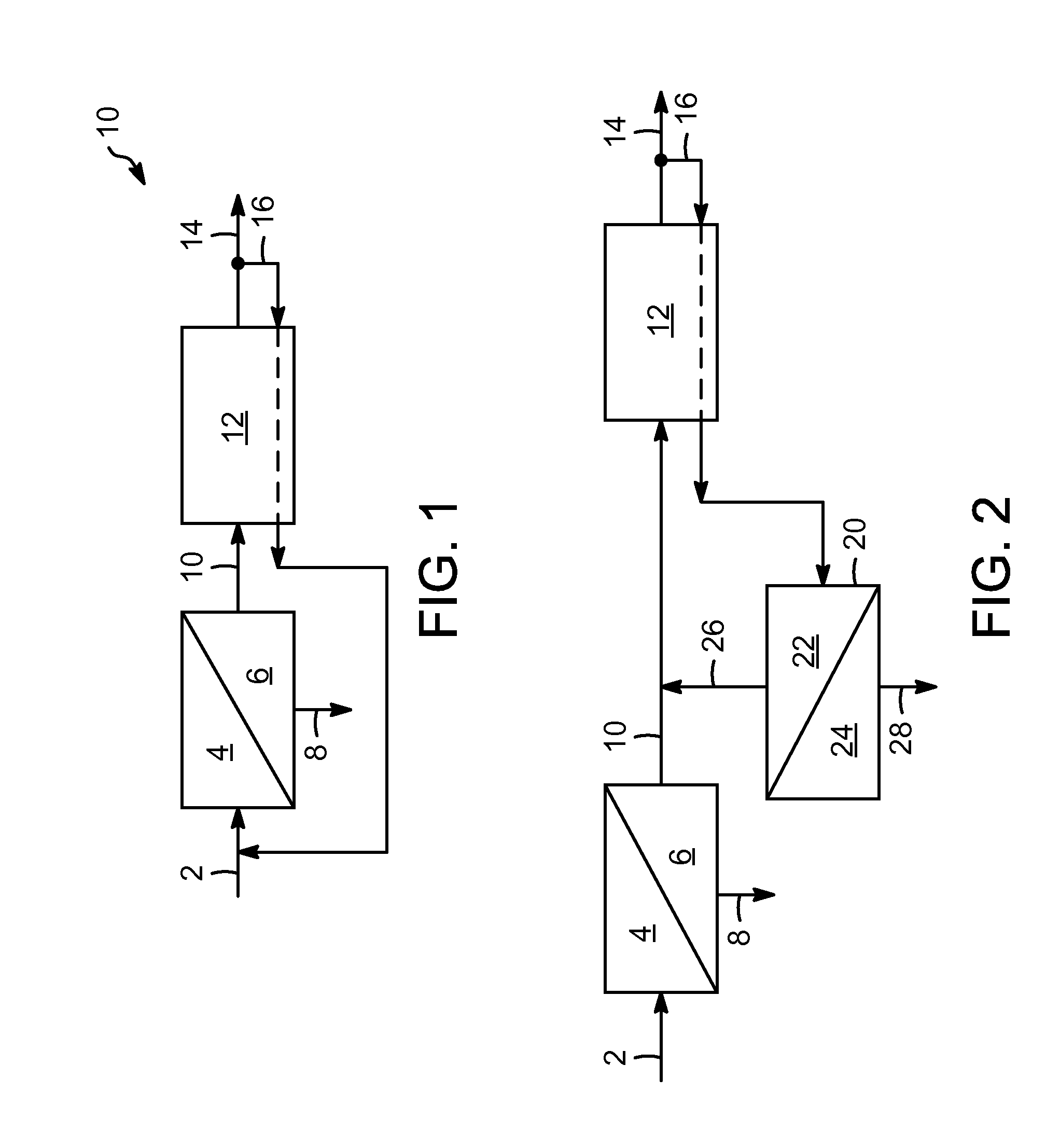
[0009] FIG. 1 shows an integrated membrane/adsorbent bed system for purifying natural gas.
[0010] FIG. 2 shows an integrated membrane/adsorbent bed system for purifying natural gas with a membrane unit to purify the regeneration stream.
[0011] FIG. 3 shows an integrated membrane/adsorbent bed system for purifying natural gas with a membrane unit and an adsorbent bed to purify the regeneration stream.
DETAILED DESCRIPTION OF THE INVENTION
[0012] In this invention, membrane and adsorption processes are combined to remove CO.sub.2 from a natural gas stream to below 50 ppm. The inlet gas stream is first processed by a membrane unit to lower the CO.sub.2 level to below about 3%. The product gas or the residue gas from the membrane is sent to a molecular sieve TSA unit to further reduce the CO.sub.2 to below 50 ppmv. In most embodiments of the invention, regeneration gas from the TSA unit, which contains the non-condensable CO.sub.2 is recycled back to the inlet of the membrane or further processed by a combination of membrane and TSA units. The invention is particularly useful for offshore application such as FLNG and operates without the use of a solvent absorption system such as an amine solvent.
[0013] The prior art practice for the front-end purification of an LNG or FLNG plant to remove CO.sub.2 and water. The membrane section may not be needed, especially if the CO.sub.2 content in the feed is low. The TSA regeneration gas generally can be recycled to the feed of the TSA because water is removed from a knock out after cooling the regeneration gas.
[0014] FIG. 1 shows one embodiment of the present invention, where a membrane unit first treats the feed gas to lower the CO.sub.2 level to below about 3%, and preferably below about 2%. The resulting partially purified natural gas feed stream is then cooled to about 45.degree. C., preferably to about 35.degree. C., more preferably to about 24.degree. C. and even more preferably cooled to below about 5.degree. C. This is followed by sending the gas to a molecular sieve TSA unit to further reduce the CO.sub.2 level to below 50 ppmv. The regeneration gas from the TSA unit, which contains the non-condensable CO.sub.2 is recycled back to the inlet of the membrane. The membrane can be of a single stage or multi-stage for increasing hydrocarbon recovery. More specifically, in FIG. 1, a feed 2 is shown entering a membrane unit 4, with carbon dioxide being removed in a permeate stream 8 and the treated natural gas going to a TSA unit 12 in line 10. The natural gas is further treated with carbon dioxide levels being reduced below 50 ppm by TSA and the fully treated natural gas is now sent to a liquefier in line 14. A small portion of the fully treated natural gas is shown sent back to the TSA unit as a regeneration stream 16 to remove the adsorbed carbon dioxide from the adsorbent and returned to feed 2 so that the majority of this carbon dioxide may be removed by the membrane unit.
[0015] FIG. 2 is another embodiment of the present invention. Referring back to the first embodiment in FIG. 1, the regeneration effluent stream 16 from the TSA unit may contain, on average, 2 to 5% of CO.sub.2, which is mixed with the inlet feed stream before the membrane unit. The feed stream can contain higher than 5% CO.sub.2, more typically higher than 10% CO.sub.2 and sometimes much higher amounts of carbon dioxide. Mixing of these two streams with disparate CO.sub.2 concentrations may result in an inefficiency of separation. Therefore, in the second embodiment of this invention, a separate membrane unit is used to treat the TSA regeneration gas. This second membrane unit removes a certain amount of CO.sub.2 from the regeneration gas and generates a residue gas that has the same CO.sub.2 composition as the residue gas from the first membrane unit. The residue gases from both membrane units are sent to the TSA. More specifically, in FIG. 2 is seen a feed 2 is shown entering a membrane unit 4, with carbon dioxide being removed in a permeate stream 8 and the treated natural gas going to a TSA unit 12 in line 10. The resulting partially purified natural gas feed stream is then preferably cooled to about 24.degree. C. and more preferably cooled to below about 5.degree. C. The natural gas is further treated with carbon dioxide levels being reduced below 50 ppm by TSA and the fully treated natural gas is now sent to a liquefier in line 14. A small portion of the fully treated natural gas is shown sent back to the TSA unit as a regeneration stream 16 to remove the adsorbed carbon dioxide from the adsorbent and then sent to a second membrane unit 24 to remove carbon dioxide in line 28 and then return the treated regeneration stream in line 26 to line 10.
[0016] Without mixing of the two gas streams with disparate CO.sub.2 concentrations, the combined size of the two membrane units is expected to be smaller than one single membrane unit as in FIG. 1 of the first embodiment. However, the TSA size can still remain quite large if the feed stream to the TSA contains high concentration of CO.sub.2, e.g. greater than 1%. This can be improved by the third embodiment of this invention as shown in FIG. 3, where the residue gas from the second membrane unit is kept at a low CO.sub.2 composition, e.g. about 0.5%, before it is sent to a second TSA unit. As the feed to this second TSA unit contains only about 0.5% of CO.sub.2, the TSA size and its associated regeneration gas can be reduced significantly. This regeneration gas is recycled back to the inlet of the second membrane unit. The size of the first TSA unit can also be reduced as its regeneration gas is no longer recycled to its feed as in the embodiment of FIG. 2. More specifically in FIG. 3 is shown a feed 2 entering a membrane unit 4, with carbon dioxide being removed in a permeate stream 8 and the treated natural gas going to a TSA unit 12 in line 10. The resulting partially purified natural gas feed stream is then preferably cooled to about 24.degree. C. and more preferably cooled to below about 5.degree. C. The natural gas is further treated with carbon dioxide levels being reduced below 50 ppm by TSA and the fully treated natural gas is now sent to a liquefier in line 14. A small portion of the fully treated natural gas is shown sent back to the TSA unit as a regeneration stream 16 to remove the adsorbed carbon dioxide from the adsorbent and then sent to a second membrane unit 24 to remove carbon dioxide in line 28, go to a second TSA unit 32 to remove carbon dioxide through line 30 and then return the treated regeneration stream in line 34 to line 14. A regeneration stream 36, which is a portion of the treated regeneration stream 34, is shown passing through second TSA unit 32 to remove carbon dioxide from the adsorbent with the TSA unit 32 and then to return to line 16 before it enters second membrane unit 24.
[0017] In summary, the features of the current invention are that the system is not susceptible to vibration or rocking from sea motion due to absence of liquid solvent amine unit. In addition to CO.sub.2, water can be removed by the membrane unit and the molecular sieve TSA unit. Both the membrane and the TSA units are integrated by further processing the regeneration gas from the TSA unit using a second membrane unit or a combination of a second membrane and a second TSA unit.
[0018] Membrane materials that can be used for CO.sub.2/CH.sub.4 separation include cellulose acetate, polyimide, perfluoro polymer, etc. Adsorbents that can be used for the CO.sub.2 removal in the TSA process include zeolite A, X or Y with different levels of Si/Al ratios and with various cationic forms such as Na, Ca, Li, K, Ba, Sr, etc. The current invention is not limited to the materials used for the membrane or the adsorption process.
[0019] The following examples demonstrate various applications of the current invention.
Example 1
[0020] A natural gas stream with a CO.sub.2 composition of 20%, a flow rate of 5,663,000 m.sup.3/day (200 MMSCFD) at 5171 kPa (750 psia) and 24.degree. C. (75.degree. F.) is to be converted to LNG. Based on the first embodiment of the current invention in FIG. 2, the gas first enters into a membrane unit to remove the bulk of CO.sub.2 and the membrane residue gas is then sent to a molecular sieve TSA unit to remove CO.sub.2 down to 50 ppm level. The regeneration off-gas from the TSA unit is recycled back to the feed of the membrane unit. The permeate gas from the membrane is burned as a fuel. The required membrane and TSA sizes and the flow rates are summarized in Table 1 for four different cases of 0.5, 1, 2 and 3% of CO.sub.2 compositions in the membrane residue stream or the feed to the TSA unit. The results are all referenced to the case with 0.5% CO.sub.2, where the calculated flow rates and equipment sizes are scaled to 100 for this case. Also included in the table are the recoveries of CH.sub.4 from the integrated process and the relative total equipment weight and footprint. As can be seen, increasing the CO.sub.2 concentration for the feed to the TSA increases the size or the sorbent volume and the regeneration gas flow of the TSA unit. However, the size of the membrane unit decreases. Overall, decreasing the CO.sub.2 concentration of the TSA feed reduces the total equipment weight, but the minimum footprint appears at about 1% CO.sub.2. The methane recovery increases with the increasing CO.sub.2 concentration for the membrane residue gas or the feed to the TSA unit.
TABLE-US-00001 TABLE 1 Simulation Results from Example 1 Feed to TSA, CO.sub.2 % 0.5% 1% 2% 3% relative flow to TSA 100 141 222 374 relative reg flow of TSA 100 214 556 1305 number of TSA beds 3 4 12 20 relative sorbent volume 100 243 631 1433 relative membrane size 100 75 62 63 relative flow to membrane 100 110 141 207 C.sub.1 recovery 100 123 137 137 relative total equipment wt. 100 123 246 588 relative total footprint 100 94 147 244
Example 2
[0021] The example is based on the first embodiment of the current invention and the same conditions as in Example 1 except that the feed temperature of the gas entering the TSA unit is cooled down to 1.7.degree. C. (35.degree. F.). As the treated gas from the TSA unit will be sent to a downstream liquefaction plant, cooling the gas to 1.7.degree. C. (35.degree. F.) is not expected to incur energy penalty. The results are summarized in Table 2, expressed in terms of relative values to the case of 0.5% CO.sub.2 in Table 1 of Example 1. Lowering feed temperature to the TSA unit not only reduces the TSA size, but also reduces its regeneration flow. Consequently, the membrane sizes are also reduced. Total equipment weight and footprint are all lower than those of Table 1.
TABLE-US-00002 TABLE 2 Simulation Results from Example 2 Feed to TSA, CO.sub.2 % 0.5% 1% 2% 3% relative flow to TSA 98 135 199 294 relative reg flow of TSA 83 175 427 876 number of TSA beds 3 3 8 16 relative sorbent volume 77 161 485 999 relative membrane size 99 73 58 55 relative flow to membrane 98 107 129 169 C.sub.1 recovery 101 126 141 145 relative total equipment wt. 94 99 191 351 relative total footprint 98 85 116 185
Example 3
[0022] The example is also based on the first embodiment of the current invention and the same conditions as in Example 1 except that a two-stage membrane is used instead of a single stage membrane. The results are listed in Table 3, again expressed in terms of relative values to the case of 0.5% CO.sub.2 in Table 1 of Example 1. In addition to the increasing sizes of the membrane units, the sizes of the TSA units are also increased due to the higher CH.sub.4 recoveries and higher membrane residue gas flows into the TSA unit. As expected, the overall equipment weight or footprint is more than that of Example 1.
TABLE-US-00003 TABLE 3 Simulation Results from Example 3 Feed to TSA, CO.sub.2 % 0.5% 1% 2% 3% relative flow to TSA 197 228 321 533 relative reg flow of TSA 197 342 804 1854 number of TSA beds 4 8 12 20 relative sorbent volume 218 372 900 1997 relative membrane size 201 128 97 98 relative flow to membrane 195 177 203 296 C.sub.1 recovery 197 199 198 195 relative total equipment wt. 214 227 346 639 relative total footprint 222 185 213 337
Example 4
[0023] The feed gas conditions are the same as Example 1, but one additional membrane unit is added to process the TSA regeneration effluent gas, following the second embodiment of the current invention in FIG. 2. This second membrane generates a residue gas with the same CO.sub.2 concentration as the residue gas from the first membrane unit. The two membrane residue gases are combined, cooled to 1.7.degree. C. (35.degree. F.) and sent to the TSA unit. The results in terms of relative numbers are shown in Table 4. Compared with Table 2 of Example 2, the overall membrane sizes are deceased because the regeneration off-gas from the TSA unit, with average CO.sub.2 compositions ranging from 2.7 to 4.9%, is sent to the second membrane unit, which avoids the inefficiency of mixing with a high CO.sub.2 composition of 20% in the feed. The improved separation efficiency of the membrane unit also increases the C.sub.1 recovery, in comparison with Example 2. However, the increased membrane residue gas flow also increases the feed to the TSA unit, and increases its size. Consequently, only a small reduction in overall equipment weight or footprint is achieved in this example.
TABLE-US-00004 TABLE 4 Simulation Results from Example 4 Feed to TSA, CO.sub.2 % 0.5% 1% 2% 3% relative flow to TSA 101 139 208 314 relative reg flow of TSA 92 180 447 939 number of TSA beds 3 3 8 16 relative sorbent volume 80 166 508 1067 relative total membrane size 94 69 51 46 relative membrane size (M2) 5 7 9 11 feed to Mem. (M2), CO.sub.2 % 2.7 3.8 4.6 4.9 C.sub.1 recovery 105 129 148 156 relative total equipment wt. 92 98 192 359 relative total footprint 95 83 113 183
Example 5
[0024] The example is also based on the second embodiment of the current invention, but with a two-stage membrane for the first membrane as in the Example 3 and a single stage membrane for the second membrane. The relative results are summarized in Table 5. In comparison with the results in Table 3, the sizes of both the membrane and the TSA units are reduced and the overall equipment weight or footprint is also decreased. Because the permeate from the second membrane is not recovered by a second stage membrane, the C.sub.1 recovery is lower than in Example 3. Consequently, the TSA sizes are reduced due to the decreased feed flows to the TSA units.
[0025] A variation of this example is to use a two-stage membrane for the second membrane and a single-stage membrane for the first membrane. The choice depends on the quality and quantity of the permeate gas, which typically can be used as a fuel source.
TABLE-US-00005 TABLE 5 Simulation Results from Example 5 Feed to TSA, CO.sub.2 % 0.5% 1% 2% 3% relative flow to TSA 188 216 303 503 relative reg flow of TSA 188 326 759 1753 number of TSA beds 4 8 12 20 relative sorbent volume 209 372 851 1921 relative total membrane size 180 109 74 68 relative membrane size (M2) 9 10 13 16 feed to Mem. (M2), CO.sub.2 % 2.4 3.2 3.9 4.2 C.sub.1 recovery 188 189 187 184 relative total equipment wt. 185 201 309 595 relative total footprint 180 152 178 290
Example 6
[0026] This example is based on the third embodiment of the current invention in FIG. 3. The example is the same as Example 4, but one additional TSA unit is used to process the residue gas from the second membrane unit, which is kept at a CO.sub.2 composition of 0.5%. The relative results are presented in Table 6, where the case for the 0.5% CO.sub.2 to the first TSA unit is omitted because the results are the same as in Table 4 of Example 4. As can be seen in Table 6, the sizes of the membrane units are increased because more CO.sub.2 is removed to reach a residue gas composition of 0.5% for the second membrane. On the other hand, the overall TSA sizes are reduced, mainly due to the reduced CO.sub.2 feed composition to the second TSA unit. This effect is more pronounced for the two cases with 2 and 3% CO.sub.2 to the first TSA unit, which results in a significant reduction of overall equipment weight or footprint. The increased size of the second membrane unit also contributes to the reduction of C.sub.1 recovery, compared to Table 4.
TABLE-US-00006 TABLE 6 Simulation Results from Example 6 Feed to TSA, CO.sub.2 % 1% 2% 3% relative flow to TSA1 109 128 137 relative reg flow of TSA1 136 261 390 relative flow to TSA2 24 44 61 relative reg flow of TSA2 26 47 51 number of beds, TSA1 3 4 6 number of beds, TSA2 2 2 3 relative total sorbent volume 152 350 414 relative total membrane size 73 66 70 relative membrane size (M2) 11 24 37 feed to Mem. (M2), CO.sub.2 % 3.5 4.2 4.7 C.sub.1 recovery 125 134 131 relative total equipment wt. 105 152 187 relative total footprint 93 104 131
* * * * *
D00000
D00001
D00002
XML
uspto.report is an independent third-party trademark research tool that is not affiliated, endorsed, or sponsored by the United States Patent and Trademark Office (USPTO) or any other governmental organization. The information provided by uspto.report is based on publicly available data at the time of writing and is intended for informational purposes only.
While we strive to provide accurate and up-to-date information, we do not guarantee the accuracy, completeness, reliability, or suitability of the information displayed on this site. The use of this site is at your own risk. Any reliance you place on such information is therefore strictly at your own risk.
All official trademark data, including owner information, should be verified by visiting the official USPTO website at www.uspto.gov. This site is not intended to replace professional legal advice and should not be used as a substitute for consulting with a legal professional who is knowledgeable about trademark law.