Device for generating an air wall in an upright refrigerated cabinet
Berben; Ernest Jozef Elias ; et al.
U.S. patent application number 12/736087 was filed with the patent office on 2011-12-29 for device for generating an air wall in an upright refrigerated cabinet. Invention is credited to Ernest Jozef Elias Berben, Peter Julien Joseph Deweerdt.
| Application Number | 20110314857 12/736087 |
| Document ID | / |
| Family ID | 40934077 |
| Filed Date | 2011-12-29 |


View All Diagrams
| United States Patent Application | 20110314857 |
| Kind Code | A1 |
| Berben; Ernest Jozef Elias ; et al. | December 29, 2011 |
Device for generating an air wall in an upright refrigerated cabinet
Abstract
A device for generating an air wall in an upright refrigerated cabinet (22) comprises a primary blower slit for generating a primary air stream (30) in the frontal opening (34) of the upright refrigerated cabinet which forms a thermal separation between the low inside temperature and the ambient air of a higher temperature. No mixing occurs between the primary air stream (30) and the secondary, optionally forced air streams (1, 9) added thereto. The thereby realized great effective heat resistance achieves that the supply of heat from the ambient air to the interior space of the refrigerated cabinet is considerably limited.
| Inventors: | Berben; Ernest Jozef Elias; (Poortvliet, NL) ; Deweerdt; Peter Julien Joseph; (Erembodegem, BE) |
| Family ID: | 40934077 |
| Appl. No.: | 12/736087 |
| Filed: | March 9, 2009 |
| PCT Filed: | March 9, 2009 |
| PCT NO: | PCT/NL2009/050109 |
| 371 Date: | September 12, 2011 |
| Current U.S. Class: | 62/256 |
| Current CPC Class: | A47F 3/0447 20130101 |
| Class at Publication: | 62/256 |
| International Class: | A47F 3/04 20060101 A47F003/04 |
Foreign Application Data
| Date | Code | Application Number |
|---|---|---|
| Mar 9, 2008 | NL | 2001356 |
Claims
1. A refrigerated cabinet comprising a device for generating an air wall for thermal separation of the air in a relatively cold first space, i.e. the interior of a refrigerated cabinet, cold room or the like for the purpose of cooled self-service presentation of prepackaged cooled food products, from the air in the relatively warm second space, i.e. the space surrounding the refrigerated cabinet or the cold room, which two spaces are mutually connected via a frontal opening extending in a substantially vertical main plane and having a height of a maximum of 2 m, the device comprising: a primary blower slit connecting to a primary blower unit positioned close to a side of the frontal opening and disposed substantially parallel to the main plane of the frontal opening, which slit extends substantially over the whole relevant dimension of the frontal opening for the purpose of generating an at least more or less flat primary air stream directed at least roughly toward the opposite side of the frontal opening, the speed of the air in the primary air stream amounts to 2-30 m/s; the width of the primary blower slit lies in the range of 5-20 mm, preferably 8-15 mm; and the length of the blower slit in the direction of the air stream lies in the range of about 50-150 mm.
2. A device as claimed in claim 1, wherein the blower slit is divided into blower channels by partitions extending in the air stream direction.
3. A device as claimed in claim 1, compromising a suction unit positioned on the opposite side of the frontal opening and having a substantially prismatic suction slit extending substantially parallel to the blower slit and having substantially the same length as the primary blower slit, to which suction slit connect suction fan means.
4. A device as claimed in claim 3, wherein the primary blower slit is connected via a duct to the suction slit, in which duct fan means are disposed which are both the primary blower fan means and the suction fan means such that the air wall forms part of a substantially closed circuit.
5. A device as claimed in claim 1, wherein the primary and the entrained secondary air streams move in vertical direction.
6. A device as claimed in claim 1, wherein at least one of the secondary air streams is an entrained air stream.
7. A device as claimed in claim 3, wherein the suction slit has a width and is disposed such that it suctions substantially only the primary air stream Sp.
8. A device as claimed in claim 3, wherein a number of regularly distributed, passive control valves are added to the suction slit for the purpose of equal, constant passing airflows, such that the same airflow passes at each longitudinal position, such that the air in the relevant air stream flows substantially in a straight path at any longitudinal position.
9. A device as claimed in claim 1, wherein the position and direction of the blower slit is adjustable.
10. A device as claimed in claim 1, comprising at least two mutually parallel blower slits.
11. A device as claimed in claim 4, wherein the duct is thermally insulated.
12. A device as claimed in claim 1 for operation in cooperation with a refrigerated cabinet and adapted to be added to a refrigerated cabinet.
13. A device as claimed in claim 12, the device being integrated with a refrigerated cabinet.
14. A device as claimed in claim 1, wherein a curved air curtain of said refrigerated cabinet runs, among other ways, according to the Coanda effect relative to the primary air stream.
15. A device as claimed in claim 5, wherein the refrigerated cabinet is provided with a static evaporator serving as cooling element, wherein the interior secondary air stream supplies air to the evaporator.
16. A device as claimed in claim 12, wherein the refrigerated cabinet is provided with an evaporator with a fan, said evaporator with fan placed at a bottom or at top of the refrigerated cabinet.
17. A device as claimed in claim 9, wherein at least two horizontal air blower slits are placed on the underside and the air coming from the air slit placed furthest outward is blown out on the top side in more or less horizontal direction.
18. A device as claimed in claim 16, wherein the air coming from the outermost air blower slit is supplied to the condenser of a cooling installation for cooling thereof such that an increased COP is obtained, for instance an increase from 3 to 8.
19. A device as claimed in claim 1 for operation in cooperation with a cold room having an air intake and wherein the created external entrained air stream is drawn in via said cold room air intake and fed back via fan means to a supply distributing box with blower slit such that the relevant air stream forms part of a substantially closed circuit.
20. A device as claimed in claim 1, wherein the air streams are supplied and discharged via at least one air distributing box, which is connected to an associated duct of substantially rectangular cross-sectional form, such that it is possible to place fan means in one box on the one side on the refrigerated cabinet and a cooling unit with a cooling group and an evaporator on the other side.
Description
[0001] The invention relates to a device for generating an air wall for thermal separation of the air in a relatively cold first space, i.e. the interior of a refrigerated cabinet, cold room or the like for the purpose of cooled self-service presentation of prepackaged cooled food products, from the air in the relatively warm second space, i.e. the space surrounding the refrigerated cabinet or the cold room, which two spaces are mutually connected via a frontal opening extending in a substantially vertical main plane and having a height of a maximum of 2 m, the device comprising: a primary blower slit connecting to a primary blower unit positioned close to a side of the frontal opening and disposed substantially parallel to the main plane of the frontal opening, which slit extends substantially over the whole relevant dimension of the frontal opening for the purpose of generating an at least more or less flat primary air stream directed at least roughly toward the opposite side of the frontal opening.
[0002] Such a device is known from WO-A-2006/115824.
[0003] Refrigerated cabinets, for instance upright refrigerated wall cabinets, and cold rooms are often equipped with an air curtain which is cooled to a slight extent, wherein the air is supplied at the top and is extracted at the bottom in order to thus keep the temperature in the area of the shelves and the bottom at a determined temperature, for instance in the range of 0.degree. C.-10.degree. C.
[0004] At the position where the above mentioned refrigerated wall cabinets and variants thereof are placed the passerby feels the cold air. As the length and concentration of these refrigerated wall cabinets increases in a supermarket or other retail space, the cold can often be felt in every limb in disagreeable manner.
[0005] In the summer this cold is unpleasant for those coming from an outside summer temperature, and has a negative effect on the buying behaviour of customers.
[0006] Another drawback is the associated energy loss. One of the causes of the energy loss is the cold usually flowing or leaking away on the underside of the air curtain. This is because the air curtain is not able to form a barrier against the cold layers accumulating at the bottom.
[0007] Another cause of energy loss is formed by the air vortices caused by passers-by. Cold likewise leaks away as a result.
[0008] A further adverse side-effect is formed by the occurrence of an external induction layer along the air curtain, with slow air stream downward from the top, and where warmer air is likewise entrained into the air curtain.
[0009] What is often also seen is that air curtains are locally closed or interrupted by merchandise which has come to lie on the suction grid of the air curtain. Cold air is hereby also lost and is generally supplemented by warmer air which must once again be cooled.
[0010] There are manufacturers of refrigerated wall cabinets who have already observed this induction layer, such as in WO-A-2006/115824.
[0011] Other manufacturers apply on the top side a controlled secondary air stream by drawing in the air for this purpose by means of fans.
[0012] Other manufacturers in turn wish to combat cold loss by feeding through the above mentioned secondary air stream on the underside and at the rear of the refrigerated wall cabinet, and then drawing in this air again at the top and feeding it back to the secondary air stream. Whatever the case, a new secondary air stream of even lower airflow rate will also be created against the secondary air stream, wherein the described construction can then be repeated.
[0013] All these solutions have the drawback that the cold losses are and remain appreciable, with associated energy loss.
[0014] In the light of the foregoing, the invention provides a device of the type stated in the preamble which has the feature that
[0015] two secondary entrained air streams Ss1 and Ss2 are added to the primary air stream Sp on either side thereof, which secondary entrained air streams have substantially the same direction as the primary air stream;
[0016] Ts1<Tp<Ts2, wherein: [0017] Ts1=the temperature of the secondary entrained air stream on the inside, [0018] Tp=the temperature of the primary air stream, [0019] Ts2=the temperature of the secondary entrained air stream on the outside;
[0020] the speed of the air in the primary air stream amounts to 2-30 m/s;
[0021] the width of the primary blower slit lies in the range of 5-20 mm, preferably 8-15 mm; and
[0022] the length of the blower slit in the direction of the air stream lies in the range of about 50-150 mm;
[0023] this such that no mixing occurs between the primary air stream Sp and the two entrained secondary air streams Ss1 and Ss2.
[0024] As conditions require, the frontal opening of the refrigerated cabinet must have single or multiple closure by one or more adapted air walls with an air stream formed by an air distributing box at the top along the length of the cabinet, with a narrow blower slit with a width in the range of about 5 to 30 mm, and wherein the air is forced to the air distributing box by two air guiding plates with a length in the flow direction of at least 10 cm. Between these two air guiding plates the air has a speed of 2-35 m/s. When the air stream from this air wall moves for instance downward from the top, it can then be guided to an evaporator and subsequently cooled and, via the air distributing box, re-enters the air wall at the top within the insulated walls of the refrigerated cabinet. This feedback of air can also be guided below and behind the cabinet in order to eventually move to the air wall via the air distributing box.
[0025] The air walls can thus be added to an existing cooled air cabinet, or the air wall can be built into the cooling circuit in the refrigerated cabinet.
[0026] In view of the air speed in the air wall, the losses will be greatly reduced compared to an air curtain.
[0027] This cooled air wall can also operate from the bottom to the top. A better cold distribution in an upright refrigerated wall cabinet is hereby obtained. The cool air in the induction flow will be forced upward unless it is not collected for other purposes.
[0028] The invention has a number of important applications, for instance:
[0029] 1) an air distributing box for an air wall, which can be added to an existing refrigerated cabinet. The built-in original air curtain will herein remain in service (see FIGS. 1-7);
[0030] 2) the construction of an upright refrigerated cabinet. The air wall is here integrated with the refrigerated cabinet. As the construction and the necessity require, it is here also possible to provide another air curtain (see FIGS. 8-11);
[0031] 3) the incorporation of an air distributing box for an air wall with cold room with open wall adjoining the retail space (see FIGS. 12, 13 and 14).
[0032] According to a specific aspect of the invention, the device can have the special feature that the blower slit is divided into blower channels by partitions extending in the air stream direction. In the case where use is made of relatively low air speeds this aspect can be technically particularly significant.
[0033] It is noted in general that the invention is intended for application in combination with refrigerated cabinets or cold rooms. It must therefore be understood that everywhere the word `refrigerated cabinet` is used, this also includes `cold room`.
[0034] The invention will now be elucidated with reference to the accompanying drawings.
[0035] In the drawings:
[0036] FIG. 1 shows a vertical section through a known refrigerated cabinet with an air curtain and an entrained secondary air stream;
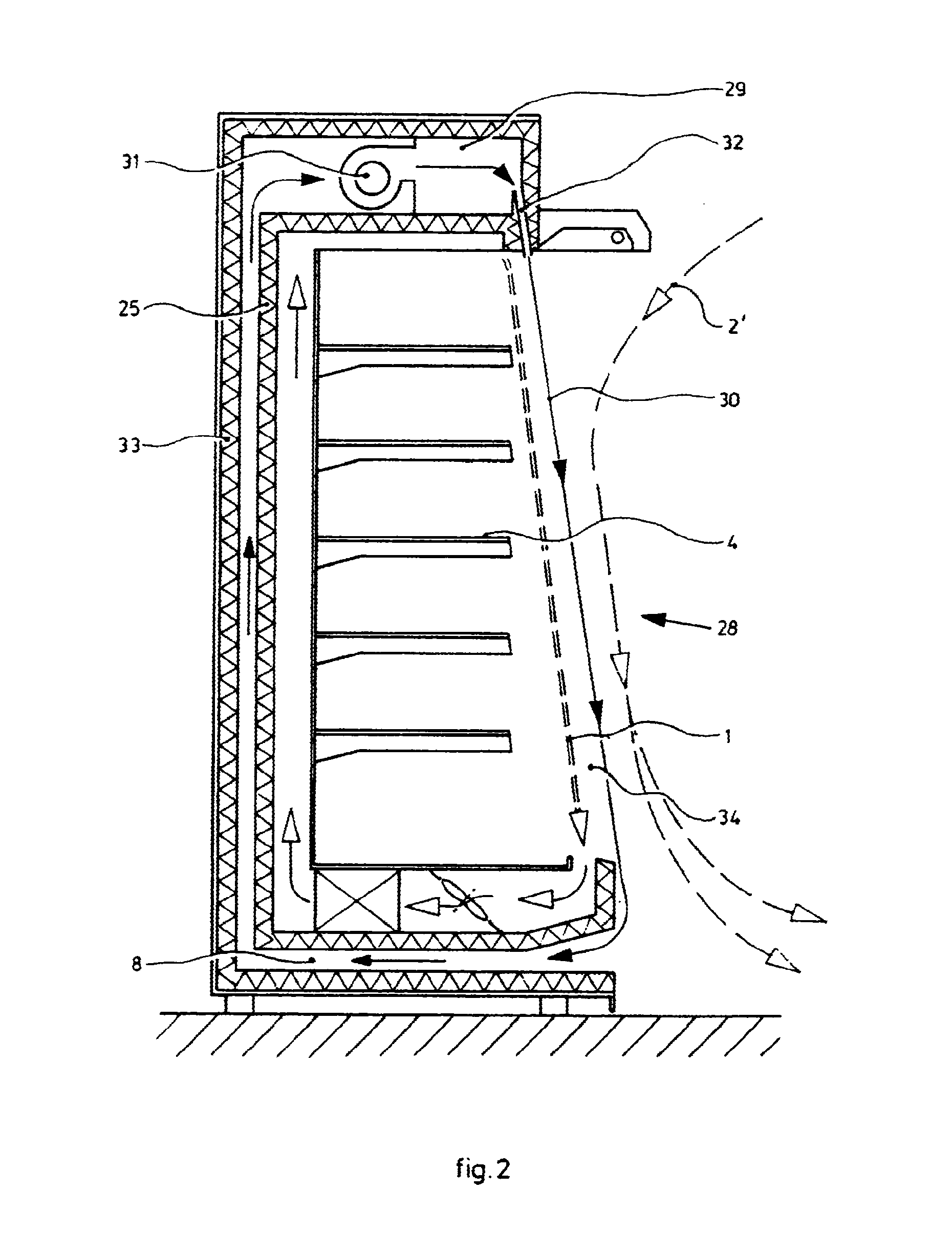
[0037] FIG. 2 shows a section corresponding to FIG. 1 to which an air distributing box is added as device according to the invention;
[0038] FIG. 3 shows an auxiliary device according to the invention, intended for addition to an existing refrigerated cabinet;
[0039] FIG. 4 shows a vertical section through a device according to the invention which generates two air walls;
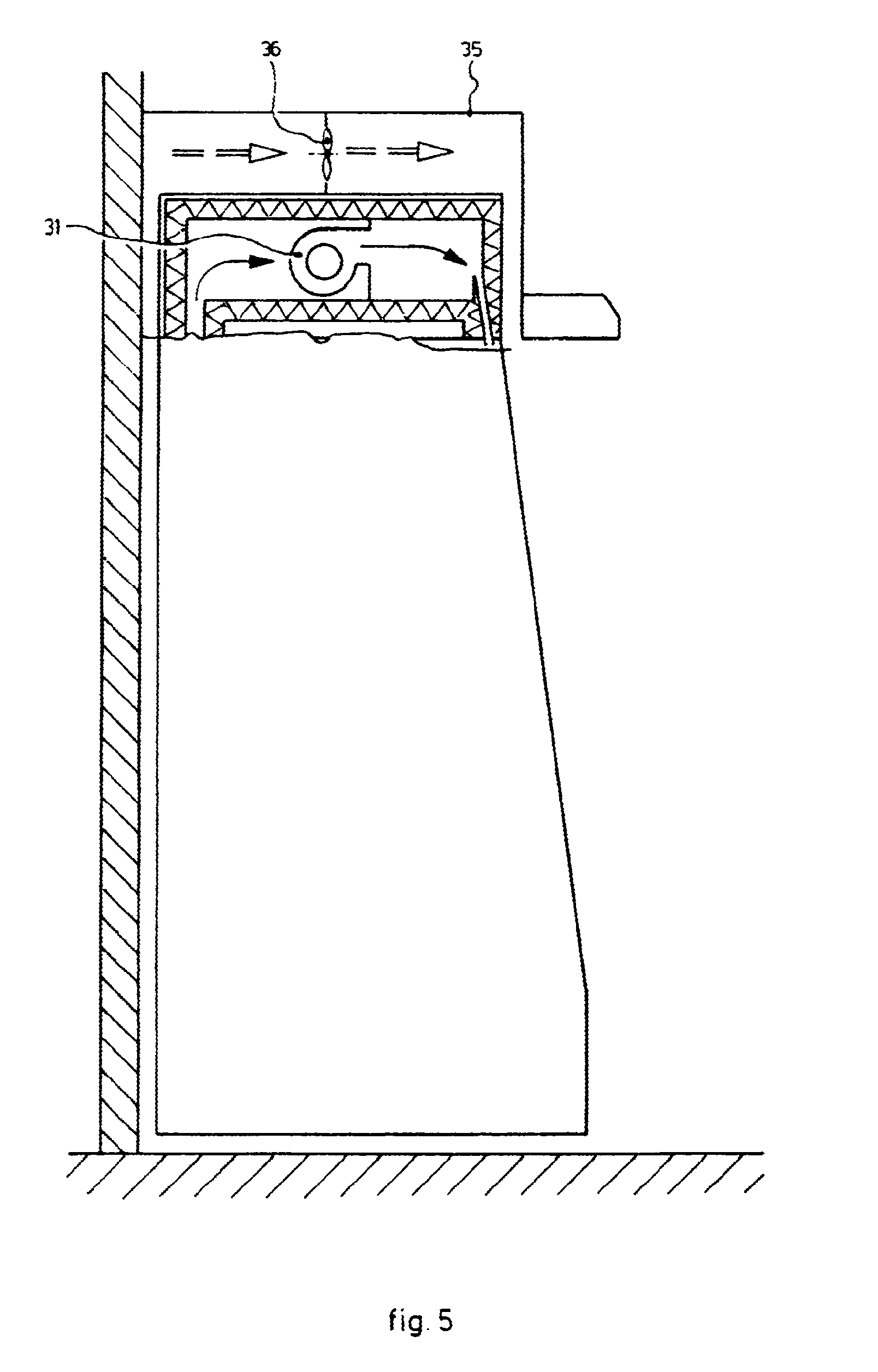
[0040] FIG. 5 shows a view corresponding to FIG. 3 of an auxiliary device as according to FIG. 4;
[0041] FIG. 6 shows a vertical section through a device similar to the device according to FIG. 2, but wherein the relevant air streams behave partly according to the Coanda effect;
[0042] FIG. 7 shows a vertical section of an arrangement similar to that according to FIG. 4, but wherein the entrained secondary air stream is drawn in and circulated;
[0043] FIG. 8 shows a vertical section through a refrigerated cabinet with a device according to the invention in yet another embodiment;
[0044] FIG. 9 shows a vertical section through an arrangement according to FIG. 8, but with a cooled inner circuit and an evaporator and a fan at the top;
[0045] FIG. 10 shows a vertical section through an arrangement wherein the air blower slit is situated on the underside instead of on the top side, and both entrained secondary air streams individually are utilized effectively;
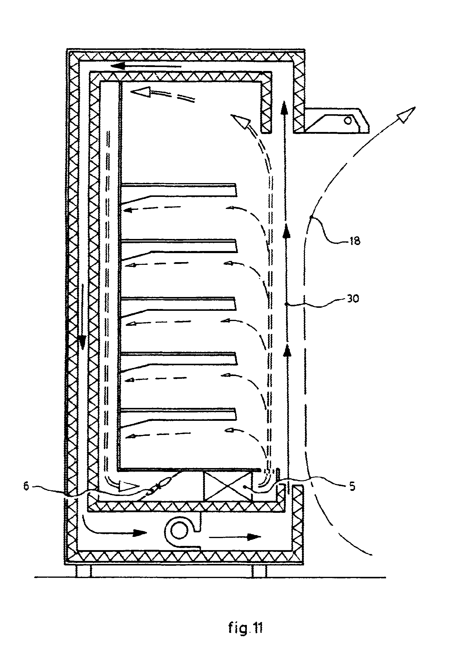
[0046] FIG. 11 shows a vertical section through a variant of the embodiment according to FIG. 10;
[0047] FIG. 12 shows a partial vertical section, wherein an air distributing box is added to an installed auxiliary device as according to FIG. 3;
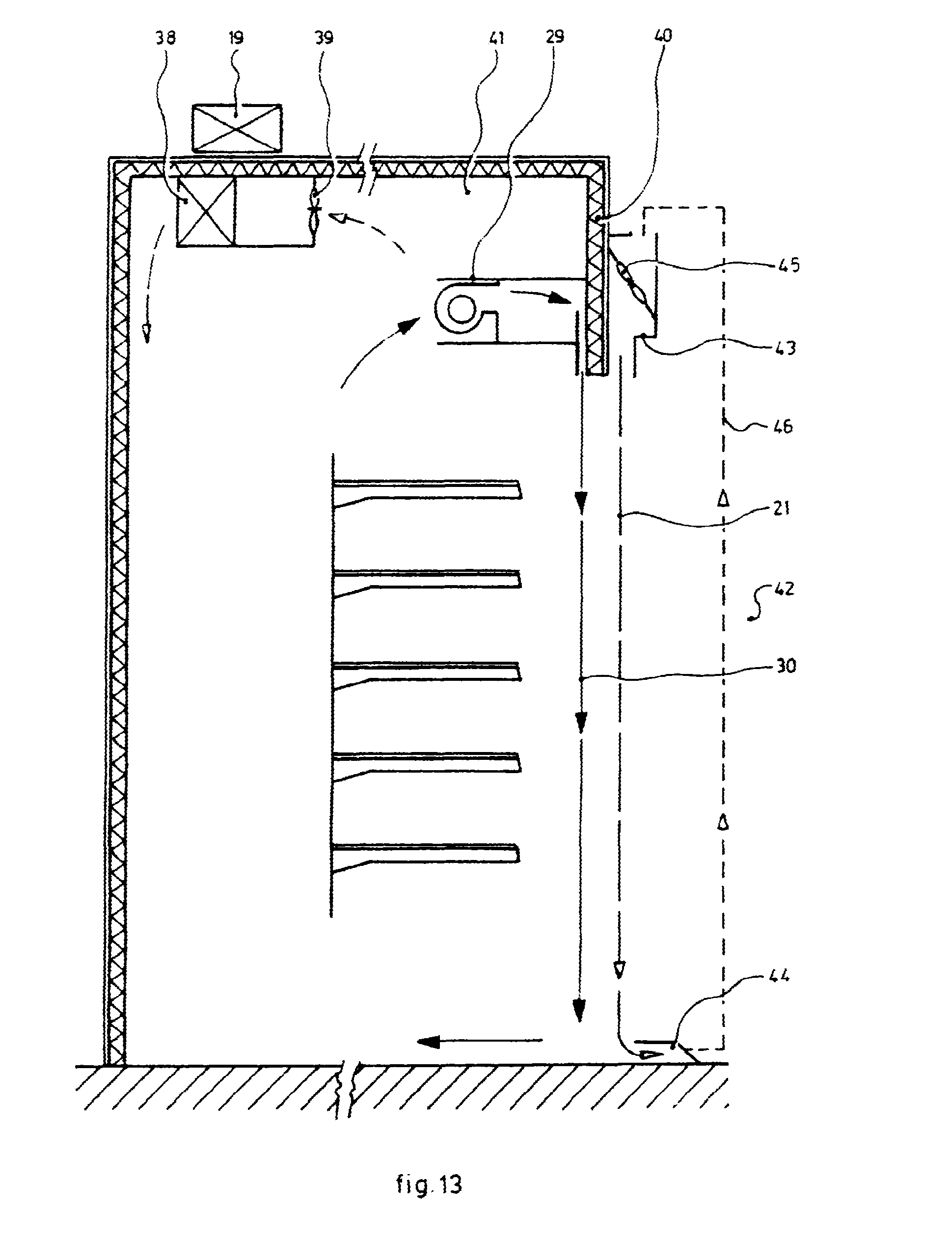
[0048] FIG. 13 shows a vertical section corresponding to FIG. 12 of an embodiment wherein a secondary air stream active in a closed circuit is applied;
[0049] FIG. 14 shows a vertical section, with partly schematically designated air streams, of a variant with an air wall in a cold room adjoining a retail space, wherein the air blower slit is situated on the underside;
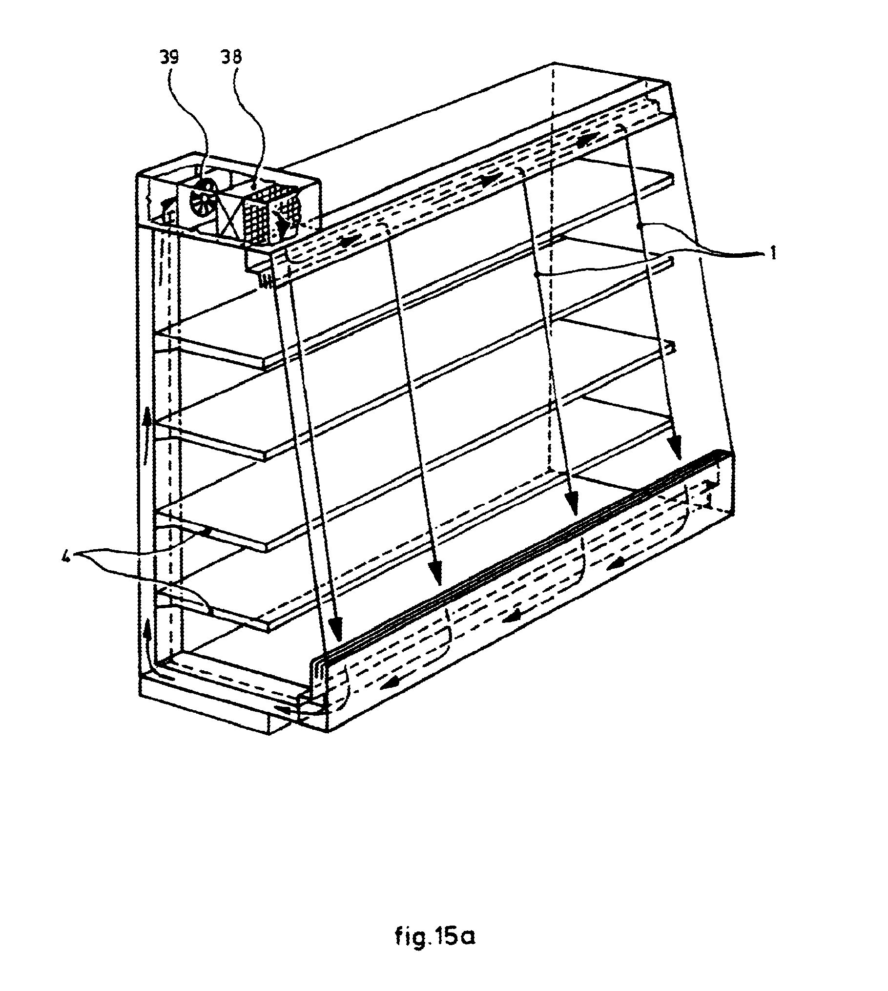
[0050] FIG. 15a shows a partially transparent perspective view of a further embodiment;
[0051] FIG. 15b shows a partially transparent perspective view of yet another embodiment; and
[0052] FIG. 16 shows a schematic front view of a refrigerated cabinet with a device according to the invention as according to the teaching of FIG. 15.
[0053] Where possible and relevant, use is made throughout the following description of the drawings of the same reference numerals for the same or at least functionally corresponding components.
[0054] FIG. 1 shows an upright refrigerated wall cabinet 22 which is provided with means for generating an air curtain 1 consisting of a more or less flat primary air stream with a small thickness and a high flow rate of 2-30 m/s. Reference numeral 2 designates the entrained secondary air stream acting on the outside. The air in the entrained secondary air stream 2 is cooled considerably as a result of the low flow rate of both air curtain 1 and entrained stream 2. The cooled air tends to accumulate to some extent in the area designated with 3 on the front side of cabinet 22 close to floor 23. The interior space of refrigerated wall cabinet 22 comprises a number of shelves, designated with reference numeral 4, for holding the food products to be presented for sale. The cabinet further comprises an evaporator 5 and a fan 6 for cooling the air flowing by, which circulates in a more or less closed circuit in the manner shown in FIG. 1. Some of the air in the stream 24 between insulated rear wall 25 and inner wall 26 reaches the space in the area of the shelves via openings 27.
[0055] FIG. 2 shows an upright refrigerated wall cabinet 28, the basic configuration of which corresponds to the structure according to FIG. 1. According to the teaching of the invention however, an air distributing box 29 is added to said cabinet, this box being adapted to generate an air wall in the form of a rapid (2-30 m/s) air stream 30 of small thickness (initial thickness 5-20 mm), which is situated on the outside relative to slow air curtain 1.
[0056] Air distributing box 29 comprises a fan 31 which draws in air wall 30 on the underside via an air duct 8 and blows it out again via a primary blower slit 32 such that a more or less closed circuit is formed. The speed of the air in this primary air stream 30 amounts to about 15 to 20 m/s. The width of blower slit 32 in the plane of the drawing is in the order of magnitude of 10-12 mm. Its length in the flow direction lies in the range of about 50-150 mm.
[0057] The entrained secondary flow on the outside is designated with reference numeral 2' in order to distinguish it from the entrained air stream 2 according to FIG. 1, which does after all flow substantially more slowly.
[0058] Attention is drawn to the fact that air duct 8 is bounded by the thermally insulating rear wall 25 and an additional thermally insulating wall 33. Cold losses, and therefore energy losses, are hereby kept as low as possible.
[0059] FIG. 3 shows the upper part of air distributing box 29.
[0060] FIG. 4 shows the configuration according to FIG. 2, but with an extension formed by an additional forced secondary outer stream 9 which forms part of an additional more or less closed air circuit. As the figure shows, the flows of respectively air curtain 1, primary air stream 30, secondary air stream 9 and the outer entrained secondary air stream 2 move substantially parallel to each other in the area of opening 34 of cabinet 22.
[0061] Relative to the configuration according to FIG. 2 the effective thermal insulation in the area of shelves 4 in cabinet 22, which can be expressed as the heat resistance between the relatively warm exterior space and the relatively warm interior space, will thus be even greater in the configuration according to FIG. 4, which is already better than in the configuration according to FIG. 2.
[0062] FIG. 5 shows that the multiple air distributing box 35 not only comprises the fan 31 for primary air stream 30, but also an additional fan 36 for the outer secondary fan.
[0063] FIG. 6 shows a configuration in which a refrigerated cabinet 37 is also provided with a lighting fixture 11. As clearly shown in the drawing, air curtain 1 departs from its normal linear path as a result of the suction of an induction air stream by primary air stream 30 according to the teaching of the invention. There is therefore a dual effect, i.e. on the one hand the suction as entrained air stream and on the other hand the Coanda effect, wherein air curtain 1 begins to behave as such an air stream. Since the configuration otherwise corresponds to that according to FIG. 2, the description of the other components is omitted here.
[0064] FIG. 7 shows a configuration wherein the second entrained air stream 10 is drawn in and circulated together with the first entrained air stream 9. The quantity of air which is drawn in on the underside must be discharged via an air outlet 12 such that the balance is guaranteed.
[0065] FIG. 8 shows a configuration wherein the air is cooled by an evaporator 5 placed in the top part of the cabinet together with an associated pressure fan 13. Cold air is carried downward via an adjustable opening 14 for the purpose of cooling the food products held by shelves 4.
[0066] FIG. 9 shows a configuration which is related to that according to FIG. 8 but which has a cooled inner circuit, comprising an evaporator 38 and a fan 39, both of which are arranged on the top side.
[0067] FIG. 10 shows a configuration with an upright cooled refrigerated wall cabinet, according to which configuration the primary stream in the air wall according to the invention flows upward from the bottom. The entrained secondary air stream 16 flowing on the inside also flows upward, whereby the possible "falling" cold air likewise flows upward. This air stream then passes the static evaporator 17. The cooled air coming from evaporator 17 automatically moves downward and reaches the space with shelves 4 via openings 27. In this configuration the pressure fan 13 is drawn on the underside. There is no technical reason for this per se; it could be placed on the top side with the same effect.
[0068] The entrained secondary air stream 18 situated on the outside also moves upward. At the top this air can be used to cool the condenser of a cooling group 19 placed there. The COP of the installation is hereby increased even further.
[0069] FIG. 11 shows a configuration which can be deemed a variant of the configuration according to FIG. 10. A ventilated evaporator 5 with a low-pressure fan 6 is applied instead of static evaporator 17. In this embodiment the closed air circuit takes roughly the same form as in the configuration according to FIG. 10.
[0070] FIG. 12 shows an arrangement wherein an air distributing box 29 according to FIG. 3 connects substantially to wall 40 of a cold room 41 adjoining a retail space 42.
[0071] An entrained secondary outer air stream 20 also results in the manner shown in this embodiment.
[0072] FIG. 13 shows a variant of the arrangement according to FIG. 12, in which is shown schematically that an outer entrained air stream 21 forms part of a closed circuit, comprising a blower unit 43 on the top side, a suction unit 44 on the underside, this suction unit being connected to the blower unit via a schematically drawn bypass 46 with a fan 45.
[0073] FIG. 14 shows schematically a variant with an air wall, which is based on a rapid, thin primary air stream 30 according to the invention, in the entrance opening of a cold room 41 adjoining a retail space 42, which flow 30 moves upward. The arrangement is closely related to that according to FIGS. 10 and 11. This relation is also manifest in the shown pattern of secondary streams 16 and 18.
[0074] In the configurations according to the above discussed embodiment according to the invention the relevant air streams are transported via elongate air blower slits, the length of which largely corresponds to the associated dimension of the relevant refrigerated cabinet. In order to save energy use could also be made of smaller ducts to carry cold air to the relevant location and to discharge it. This is also the case for the air distribution. This could imply that it is possible to suffice with placing units to the left and right relative to the cabinet. Nor is necessary under all circumstances to arrange multiple insulating layers in the cabinet. Omission thereof makes the construction of a cabinet simpler and cheaper, albeit with the likely drawback of a slightly lower efficiency.
[0075] FIGS. 15a and 15b show variants of refrigerated cabinets to which air wall devices according to the invention are added.
[0076] FIG. 16 shows a front view of a refrigerated cabinet with a device according to the invention, which is provided with shelves 4 for holding products to be presented for sale.
[0077] According to the invention the air wall can be applied in single arrangement to thermally separate the relatively warm ambient air from the relatively cold air in the interior of a refrigerated cabinet or cold room. If the temperature difference over this single air wall is small, there will be little heat loss.
[0078] In the case where two parallel air walls according to the invention are placed, the heat losses per applied air wall will decrease still further.
[0079] If a further secondary air stream fed by indrawn air is applied in the same direction in the case of a single air wall or two or more parallel air walls, an exceptionally small heat loss is then realized. Such add-ons must be balanced against the power required for the pressure fan which must be applied for each forced air stream.
[0080] Should it be wished to place an air distributing box for air walls on the top side of the refrigerated wall cabinet, the elongate lighting fixture may then be in the way. In this case it is possible to remove the lighting unit, position the outlet of the air distributing box there, and subsequently place the lighting unit thereon. It is usually necessary in this case to ensure that the direction of the air blower slit is adjustable, namely such that the primary air stream exits at the bottom edge of the cabinet. The intention here is to separate the cooled internal air stream circuit from the air wall.
[0081] The advantages of the invention can be summarized briefly as follows:
[0082] 1) There is a high effective heat resistance at the position of the vertical opening, whereby energy losses are greatly limited.
[0083] 2) The temperature in the interior space of the refrigerated cabinet can be better maintained within narrow limits.
[0084] 3) The construction according to the invention is simple, inexpensive and effective.
[0085] 4) A refrigerated cabinet can suffice with a smaller cooling installation and therefore be cheaper.
[0086] 5) Existing refrigerated cabinets can be supplemented with a unit according to the invention, whereby replacement of existing and still very serviceable refrigerated cabinets is not necessary.
[0087] 6) It is possible to realize a higher COP by using air from an entrained secondary air stream for the purpose of cooling a condenser.
[0088] 7) The invention can also be applied when selling from cold rooms.
[0089] 8) The structure according to the invention can also be applied in the case where a lighting fixture is situated inside the cooled space.
CITED LITERATURE
[0090] WO-A-2006/115824
* * * * *
D00000
D00001
D00002
D00003
D00004
D00005
D00006
D00007
D00008
D00009
D00010
D00011
D00012

D00013
D00014

D00015
D00016

D00017

XML
uspto.report is an independent third-party trademark research tool that is not affiliated, endorsed, or sponsored by the United States Patent and Trademark Office (USPTO) or any other governmental organization. The information provided by uspto.report is based on publicly available data at the time of writing and is intended for informational purposes only.
While we strive to provide accurate and up-to-date information, we do not guarantee the accuracy, completeness, reliability, or suitability of the information displayed on this site. The use of this site is at your own risk. Any reliance you place on such information is therefore strictly at your own risk.
All official trademark data, including owner information, should be verified by visiting the official USPTO website at www.uspto.gov. This site is not intended to replace professional legal advice and should not be used as a substitute for consulting with a legal professional who is knowledgeable about trademark law.