Tadem Compressor Operation
Lifson; Alexander ; et al.
U.S. patent application number 12/672742 was filed with the patent office on 2011-12-29 for tadem compressor operation. This patent application is currently assigned to CARRIER CORPORATION. Invention is credited to Alexander Lifson, Michael F. Taras.
| Application Number | 20110314845 12/672742 |
| Document ID | / |
| Family ID | 40549443 |
| Filed Date | 2011-12-29 |
| United States Patent Application | 20110314845 |
| Kind Code | A1 |
| Lifson; Alexander ; et al. | December 29, 2011 |
TADEM COMPRESSOR OPERATION
Abstract
A refrigerant system operates with tandem compressors. As is known, one or more of the tandem compressors can be shut down at part-load operating conditions when lower refrigerant system capacity is required. A control periodically engages at least one shut down tandem compressor for a short period of time. This increases the refrigerant mass flow of refrigerant throughout the refrigerant system to ensure that oil travels through the system and is not retained in the system.
| Inventors: | Lifson; Alexander; (Manlius, NY) ; Taras; Michael F.; (Fayetteville, NY) |
| Assignee: | CARRIER CORPORATION Syracuse NY |
| Family ID: | 40549443 |
| Appl. No.: | 12/672742 |
| Filed: | October 10, 2007 |
| PCT Filed: | October 10, 2007 |
| PCT NO: | PCT/US2007/080873 |
| 371 Date: | February 9, 2010 |
| Current U.S. Class: | 62/115 ; 62/228.1; 62/468 |
| Current CPC Class: | F25B 2400/075 20130101; F25B 2600/0251 20130101; F25B 49/022 20130101; F25B 2400/13 20130101; F25B 2600/23 20130101 |
| Class at Publication: | 62/115 ; 62/468; 62/228.1 |
| International Class: | F25B 49/02 20060101 F25B049/02; F25B 1/00 20060101 F25B001/00; F25B 41/00 20060101 F25B041/00 |
Claims
1. A refrigerant system having a compressor unit comprising: a plurality of tandem compressors, said plurality of tandem compressors utilized for compressing a refrigerant, and delivering the refrigerant throughout the refrigerant system, and to at least one heat rejection heat exchanger, an expansion device and at least one evaporator; and a control for operating said refrigerant system having capability to shut down at least one of said plurality of tandem compressors to provide unloading of the refrigerant system, and said control periodically moving into an oil return mode by engaging at least one shutdown compressor for at least one short period of time to increase refrigerant mass flow rate and facilitate oil return.
2. The refrigerant system as set forth in claim 1, wherein said plurality of tandem compressors have both a common suction manifold and a common discharge manifold.
3. The refrigerant system as set forth in claim 1, wherein said plurality of tandem compressors have at least one of a common suction manifold and a common discharge manifold.
4. The refrigerant system as set forth in claim 1, wherein the compressor unit incorporates at least one economized tandem compressor.
5. The refrigerant system as set forth in claim 1, wherein the compressor unit incorporates at least two economized tandem compressors also having a common intermediate manifold.
6. The refrigerant system as set forth in claim 1, wherein the compressor engagement is controlled based on a safety device or sensor feedback.
7. The refrigerant system as set forth in claim 6, wherein the sensor is an oil level sensor.
8. The refrigerant system as set forth in claim 1, wherein compressor engagement is based on at least one environmental or operating control parameter.
9. The refrigerant system as set forth in claim 8, wherein the control parameter being a shutdown time for at least one of the shutdown compressors.
10. The refrigerant system as set forth in claim 9, wherein an additional control parameter is included, and is at least one of a saturation suction temperature, suction pressure, evaporator secondary fluid temperature, oil temperature, and suction temperature.
11. The refrigerant system as set forth in claim 1, wherein the short period of time is predetermined.
12. The refrigerant system as set forth in claim 1, wherein the short period of time is defined by at least one of the following control parameters: saturation suction temperature, suction pressure, evaporator secondary fluid temperature, oil temperature, suction temperature, temperature variations in the conditioned environment, humidity variation in the conditioned environment.
13. The refrigerant system as set forth in claim 1, wherein said control engages a shutdown compressor after a predetermined period of time has elapsed with said at least one compressor being shut down.
14. The refrigerant system as set forth in claim 13, wherein the elapsed shutdown period of time is between 30 minutes and 12 hours.
15. The refrigerant system as set forth in claim 1, wherein the short period of time is between 10 seconds and 10 minutes.
16. The refrigerant system as set forth in claim 13, wherein said at least one compressor being engaged for a plurality of short periods of time in sequence.
17. The refrigerant system as set forth in claim 1, wherein said engaged at least one compressor is again shut down after it has been engaged for a short period of time.
18. The refrigerant system as set forth in claim 1, wherein multiple compressors are brought online in sequence.
19. The refrigerant system as set forth in claim 1, wherein multiple compressors are brought online simultaneously.
20. The refrigerant system as set forth in claim 1, wherein multiple compressors are shutdown in sequence.
21. The refrigerant system as set forth in claim 1, wherein multiple compressors are shutdown simultaneously.
22. A method of operating a refrigerant system including the steps of: providing a compressor unit comprising a plurality of tandem compressors, said plurality of tandem compressors compressing a refrigerant, and delivering the refrigerant throughout the refrigerant system, and to at least one heat rejection heat exchanger, an expansion device and at least one evaporator; and controlling said refrigerant system to shut down at least one of said plurality of tandem compressors to provide unloading of the refrigerant system, and periodically moving into an oil return mode by engaging at least one shutdown compressor for at least one short period of time to increase refrigerant mass flow rate and facilitate oil return.
23. The method as set forth in claim 22, wherein the compressor engagement is controlled based on a safety device or sensor feedback.
24. The method as set forth in claim 22, wherein compressor engagement is based on at least one environmental or operating control parameter.
25. The method as set forth in claim 22, wherein the short period of time is defined by at least one of the following control parameters: saturation suction temperature, suction pressure, evaporator secondary fluid temperature, oil temperature, suction temperature, temperature variations in the conditioned environment, humidity variation in the conditioned environment.
Description
BACKGROUND OF THE INVENTION
[0001] This application relates to a refrigerant system having tandem compressors, wherein at least one compressor that has been shut down for a prolonged period of time, is periodically engaged for a short period of time to ensure proper oil return throughout the refrigerant system back to the tandem compressors.
[0002] Heating, ventilation, air conditioning and refrigeration (HVAC&R) systems are utilized to condition various environments. The HVAC&R systems typically use a refrigerant circulating throughout a closed-loop refrigerant circuit and are applied as air conditioners, heat pumps, refrigeration units, etc. Various enhancement techniques and system configurations are known and implemented to provide a required performance over a wide spectrum of environmental conditions to satisfy diverse thermal load demands.
[0003] In a very basic refrigerant system, a compressor compresses a refrigerant and delivers it downstream to a heat rejection heat exchanger, which is a condenser for subcritical applications and a gas cooler for transcritical applications. Refrigerant passes from the condenser to an expansion device, and from the expansion device to an evaporator. From the evaporator, refrigerant returns to the compressor. This basic refrigerant system is typically supplemented and enhanced by a number of different options and features to satisfy application requirements.
[0004] One such enhancement is the use of tandem compressors. Tandem compressors include a plurality of compressors operating in parallel each typically receiving refrigerant from a common suction manifold, each separately compressing the refrigerant and typically delivering the refrigerant to a common discharge manifold. Each of these compressors may be independently turned on or off to vary refrigerant system capacity at part-load operation. In this manner, the capacity provided by the tandem compressor subsystem to the overall refrigerant system can be tailored to the thermal load demands in the conditioned space as well as environmental conditions. Quite often, tandem compressor configurations include oil and/or vapor equalization lines connecting tandem compressors for functionality and reliability enhancement. Also, tandem compressors having only one suction or discharge common manifold are known in the art. Further, tandem compressor configurations may include at least some economized compressors that may have a common economizer manifold.
[0005] One concern with tandem compressors occurs when at least one of the tandem compressors is shut off under system part-load conditions. As one compressor is shut down, the refrigerant mass flow through the refrigerant system is substantially reduced, which can often lead to problems associated with lubrication oil not being returned back to the compressors. This occurs as reduced refrigerant mass flow causes oil to be retained throughout the refrigerant system, and in the evaporator in particular. This problem can become especially acute in refrigerant systems equipped with microchannel heat exchangers, since the size of the refrigerant channels in these heat exchangers is particularly small, and refrigerant flow may not have enough momentum to overcome viscous drag forces and to carry oil with it. The cause for the oil holdup and poor oil return back to the compressor unit is that the refrigerant mass flow throughout the refrigerant system and its components could be drastically reduced when some of the tandem compressors are shut off. Additionally, lubrication oil logged in the refrigerant system heat exchangers causes performance degradation for the heat exchanger and entire refrigerant system.
SUMMARY OF THE INVENTION
[0006] When a refrigerant system is operating with at least one tandem compressor turned off for a prolonged period of time, that one tandem compressor is periodically engaged for a short period of time. By engaging the shutdown compressor, the refrigerant mass flow through the system is increased instantaneously. In some applications, several or all of the tandem compressors can be engaged simultaneously or in sequence during this short period of time. When tandem compressors are activated in sequence, they can be deactivated in sequence as well or shut off simultaneously.
[0007] These and other features of the present invention can be best understood from the following specification and drawings, the following of which is a brief description.
BRIEF DESCRIPTION OF THE DRAWINGS
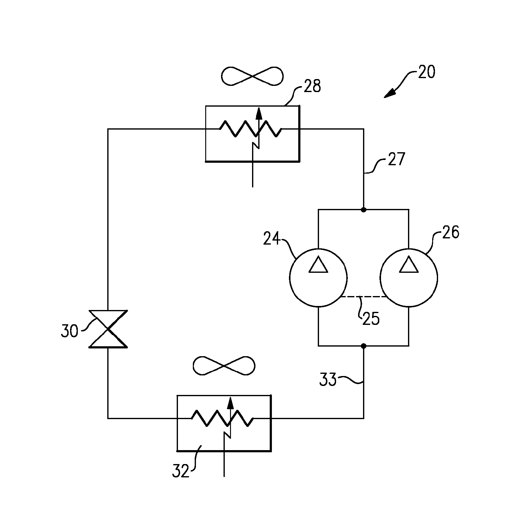
[0008] FIG. 1 shows a schematic view of a refrigerant system incorporating tandem compressors having common suction and common discharge manifolds.
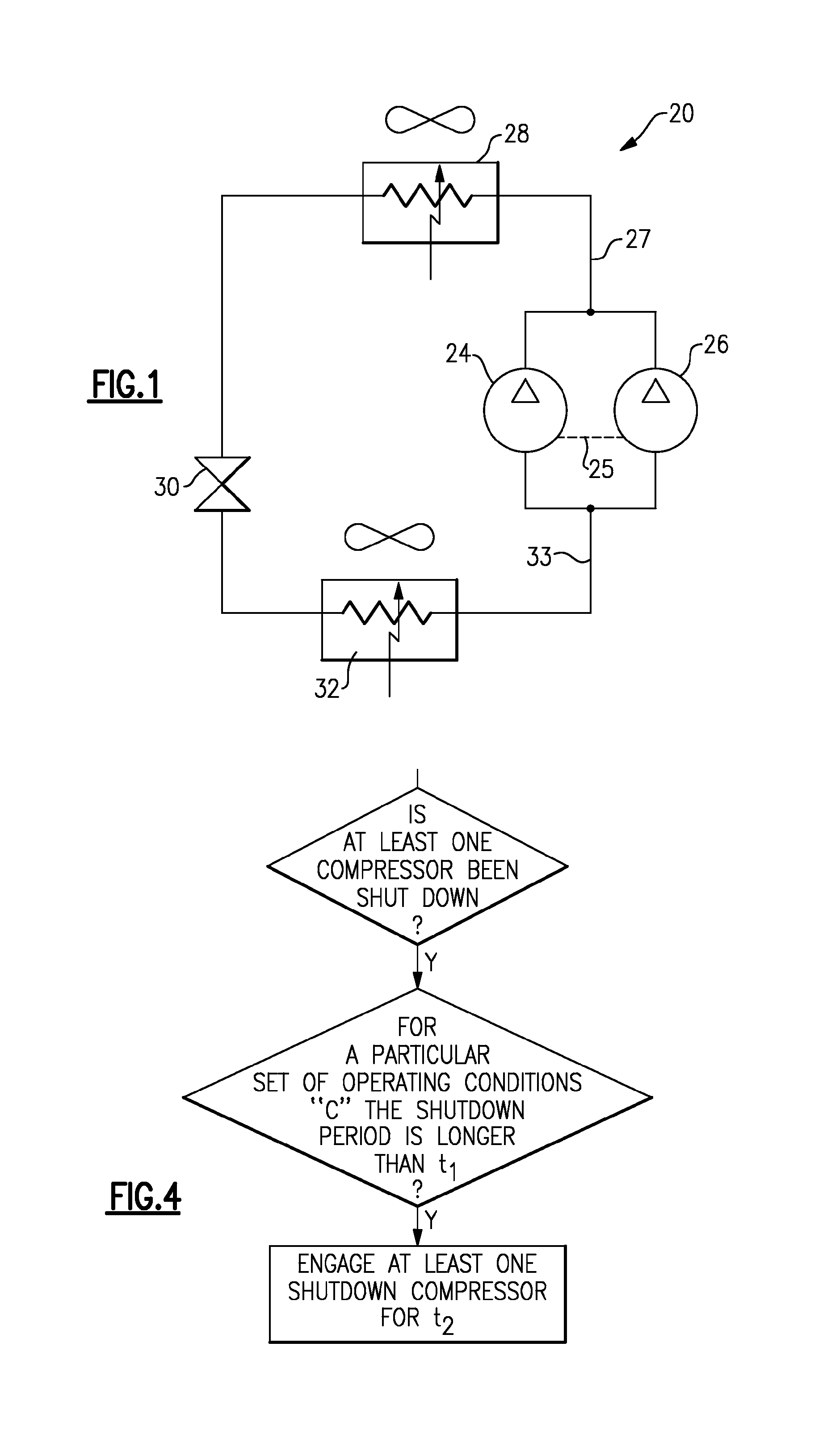
[0009] FIG. 2A shows a schematic view of a refrigerant system incorporating tandem compressors having a common suction manifold.
[0010] FIG. 2B shows a schematic view of a refrigerant system incorporating tandem compressors having a common discharge manifold.
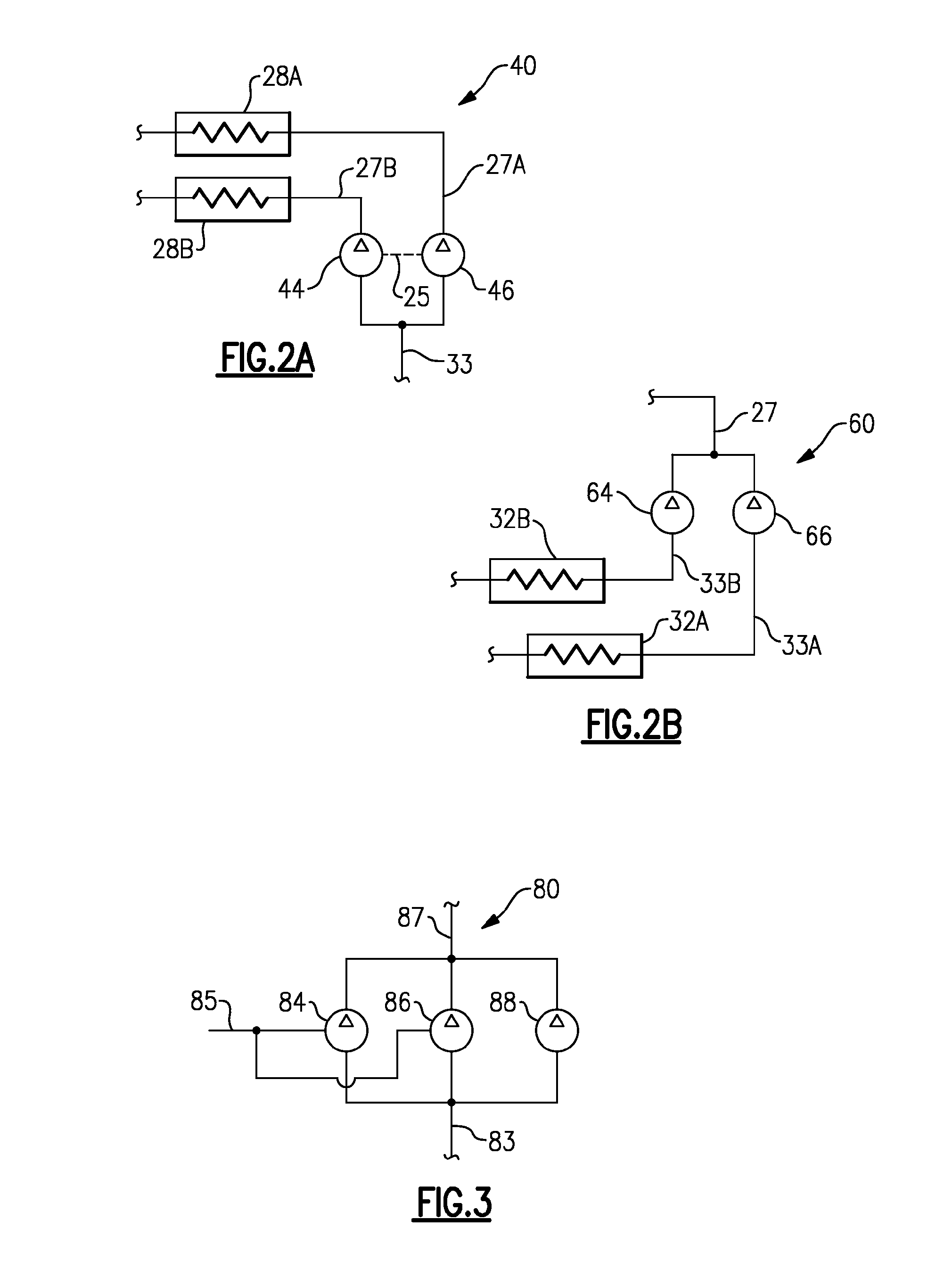
[0011] FIG. 3 shows a schematic view of an economized refrigerant system incorporating tandem economized and non-economized compressors.
[0012] FIG. 4 is a control logic flow chart.
DETAILED DESCRIPTION OF THE PREFERRED EMBODIMENTS
[0013] FIG. 1 shows a refrigerant system 20 incorporating tandem compressors 24 and 26. The tandem compressors 24 and 26 compress a refrigerant and deliver it to a common discharge manifold 27 then through a heat rejection heat exchanger 28, to an expansion device 30, to an evaporator 32, and to a common suction manifold 33 leading back to the tandem compressors 24 and 26. The tandem compressors 24 and 26 are often connected by an oil equalization line 25 and may be connected by an optional vapor equalization line (not shown). Also, all or some of the tandem compressors may have optional discharge shutoff valves (not shown) to prevent refrigerant backflow when these compressors are shut down, while the other compressors are still operating. As is known, at part-load operation, to satisfy reduced thermal load demands in the conditioned space and/or provide operation at a wide spectrum of environmental conditions, a control for the refrigerant system 20 (not shown) may shut down either of the compressors 24 or 26 for a prolonged period of time. When this occurs, the mass flow of refrigerant passing through the refrigerant system 20 is significantly reduced. Lubrication oil that is entrained in the refrigerant may be retained in the components of the refrigerant system 20, and in the evaporator 32 in particular, due to this low refrigerant mass flow circulating throughout the system. This is undesirable in that the retained oil degrades performance of the heat exchangers 28 and 32 of the refrigerant system 20, and in particular, performance of the evaporator 32. Moreover, if oil is pumped out from the tandem compressors 24 and 26 and is not returned back to the compressors, this may result in less oil than would be desired for a reliable operation of the tandem compressors 24 and 26. Low lubrication oil amounts returned to the tandem compressors 24 and 26 may cause severe damage of compressor components, prolonged maintenance intervals and expensive repairs. Of course, the tandem compressors 24 and 26 may be of different sizes (capacities), and there may be more than two compressors connected in tandem within the refrigerant system 20.
[0014] FIGS. 2A exhibits a refrigerant system 40 with tandem compressors 44 and 46 having a common suction manifold 33 and separate discharge lines 27A and 27B leading to separate heat rejection heat exchangers 28A and 28B, typically operating at different temperature levels. In all other aspects of design and operation the FIG. 2A embodiment 40 is similar to the refrigerant system 20.
[0015] FIGS. 2B exhibits a refrigerant system 60 with tandem compressors 64 and 66 having a common discharge manifold 27 and separate suction lines 33A and 33B leading from separate evaporators 32A and 32B, typically operating at different temperature levels. In all other aspects of design and operation the FIG. 2B embodiment 60 is similar to the refrigerant system 20.
[0016] FIG. 3 shows a refrigerant system 80 with economized tandem compressors 84 and 86 and non-economized tandem compressor 88 having common suction manifold 83 and common discharge manifold 87. Tandem economized compressors 84 and 86 also have a common intermediate pressure manifold 85. As known, economized compressors may be represented either by sequential compression stages or separate compressors connected in sequence.
[0017] The oil return problem can become especially acute when the economized compressor is shutdown for a prolonged period of time, as substantial amount of oil can be retained in the non-operating economizer heat exchanger and the economizer lines leading to the compressors.
[0018] FIG. 4 shows exemplary control logic for an improved operation of the tandem compressors. For instance, a control for the refrigerant system 20, 40, 60 or 80 determines whether at least one of the tandem compressors has been shut down. If that compressor has been shut down longer than a particular period of time t.sub.1 for a particular set of operating conditions "c", then at least one shutdown tandem compressor is engaged for a short period of time t.sub.2. Normally, the decision to engage the shutdown compressor may be made if the shutdown period of time is between 30 minutes and 12 hours. As an example, the operating conditions "c" can be represented by a saturation suction temperature or suction pressure. In this manner, the mass flow of refrigerant through the refrigerant system is instantaneously increased, and the lubrication oil retained within the refrigerant system components will be driven out and returned to the tandem compressors assuring their reliable operation and improved performance of the refrigerant system.
[0019] The engagement of the shutdown compressors need not be for any undue length of time, simply, it should be long enough to ensure the proper oil return and short enough not to disrupt the controlled parameters in the conditioned space. The duration of compressor engagement can normally vary from 10 seconds to 10 minutes. As explained above, the time intervals t.sub.2 and t.sub.1 can be adjusted based upon environmental conditions and/or system operational characteristics, and depend on a particular configuration of the refrigerant system and tandem compressor unit. For instance, if one of two equally sized tandem compressors of the basic refrigerant system was shutdown for more than 2 hours at a saturated suction temperature of 45.degree. F., this compressor can be activated for 2 minutes and then shut down again. To enhance oil return even further, a shutdown tandem compressor can be activated several times in sequence within a short period of time. This will create intermittent refrigerant flow that will facilitate the oil return process. For instance, for the example cited above, the shutdown tandem compressor can be activated 3 times for 1 minute intervals with 30 second 2 shutdown periods in between these intervals.
[0020] Furthermore, the shutdown tandem compressor engagement may be based upon a compressor safety device or a sensor. For instance, an oil level sensor may be installed in the compressor sump. If the oil level falls below a predetermined level, then at least one of the shutdown tandem compressors is turned on by the refrigerant system controller that had received a feedback from the oil level sensor.
[0021] If a refrigerant system has multiple (more than two) tandem compressors, such as shown in FIG. 3 embodiment, the shutdown tandem compressors can be engaged and disengaged individually, simultaneously or in sequence. Also, the tandem compression systems may have a nested structure, where each of the subsystem configured for tandem operation may have an internal structure itself consisting of tandem compressors. Further, each of the tandem compressors may comprise a number of sequential compression stages or several compressors connected in sequence.
[0022] The present invention augments time-averaged refrigerant system performance (capacity and efficiency) by removing the unwanted excessive oil from the internal surfaces of the heat rejection heat exchanger and evaporator, improving heat transfer and pressure drop characteristics for these heat exchangers. Also, system reliability is improved by ensuring the compressor has adequate lubrication oil amount. This application is especially beneficial for microchannel heat exchangers, where the oil return problem becomes especially prevalent. No new hardware is required for achieving this invention, and only the control logic for operation of the refrigerant systems having tandem compressors need to be enhanced. Further, this invention can be applied to newly built refrigerant systems and even to those systems that are now installed in the field. Also, it has to be recognized that the refrigerant system may be operated in the oil return mode during normal occupancy hours of the conditioned space or may be preferably controlled in this mode during unoccupied hours.
[0023] It should be pointed out that many different compressor types could be used in this invention. For example, scroll, screw, rotary, or reciprocating compressors can be employed.
[0024] The refrigerant systems that utilize this invention can be used in many different applications, including, but not limited to, air conditioning systems, heat pump systems, marine container units, refrigeration truck-trailer units, and supermarket refrigeration systems.
[0025] Although the embodiments of this invention have been disclosed, a worker of ordinary skill in this art would recognize that certain modifications would come within the scope of this invention. For that reason, the following claims should be studied to determine the true scope and content of this invention.
* * * * *
D00000
D00001
D00002
XML
uspto.report is an independent third-party trademark research tool that is not affiliated, endorsed, or sponsored by the United States Patent and Trademark Office (USPTO) or any other governmental organization. The information provided by uspto.report is based on publicly available data at the time of writing and is intended for informational purposes only.
While we strive to provide accurate and up-to-date information, we do not guarantee the accuracy, completeness, reliability, or suitability of the information displayed on this site. The use of this site is at your own risk. Any reliance you place on such information is therefore strictly at your own risk.
All official trademark data, including owner information, should be verified by visiting the official USPTO website at www.uspto.gov. This site is not intended to replace professional legal advice and should not be used as a substitute for consulting with a legal professional who is knowledgeable about trademark law.