Hydraulically Activated Exhaust Flap
Richter; Bjorn ; et al.
U.S. patent application number 12/968877 was filed with the patent office on 2011-12-29 for hydraulically activated exhaust flap. This patent application is currently assigned to Benteler Automobiltechnik GmbH. Invention is credited to Sven Przybylski, Bjorn Richter.
| Application Number | 20110314799 12/968877 |
| Document ID | / |
| Family ID | 43243795 |
| Filed Date | 2011-12-29 |

| United States Patent Application | 20110314799 |
| Kind Code | A1 |
| Richter; Bjorn ; et al. | December 29, 2011 |
HYDRAULICALLY ACTIVATED EXHAUST FLAP
Abstract
A flap arrangement in an exhaust track of a motor vehicle includes an exhaust flap and a slave cylinder for controlling an operative position of the exhaust flap. The slave cylinder is fluidly connected to a master cylinder by a hydraulic line containing a hydraulic fluid in the form of liquid metal. The movement of the master cylinder is thus transmitted via the liquid metal to the slave cylinder. A mechanical coupling of the slave cylinder with the exhaust flap moves the exhaust flap to a respective operative position.
| Inventors: | Richter; Bjorn; (Paderborn, DE) ; Przybylski; Sven; (Paderborn, DE) |
| Assignee: | Benteler Automobiltechnik
GmbH Paderborn DE |
| Family ID: | 43243795 |
| Appl. No.: | 12/968877 |
| Filed: | December 15, 2010 |
| Current U.S. Class: | 60/324 |
| Current CPC Class: | F01N 13/087 20130101 |
| Class at Publication: | 60/324 |
| International Class: | F01N 13/00 20100101 F01N013/00 |
Foreign Application Data
| Date | Code | Application Number |
|---|---|---|
| Dec 15, 2009 | DE | 102009058171.5-13 |
Claims
1. A flap arrangement in an exhaust track of a motor vehicle, comprising: an exhaust flap; a slave cylinder for controlling an operative position of the exhaust flap; and a master cylinder fluidly connected to the slave cylinder by a hydraulic line containing a hydraulic fluid in the form of liquid metal.
2. The flap arrangement of claim 1, wherein the exhaust flap is mechanically coupled with the slave cylinder.
3. The flap arrangement of claim 1, further comprising an adjusting actuator coupled with the master cylinder to control operation of the master cylinder.
4. The flap arrangement of claim 3, wherein the adjusting actuator is a linear actuator.
5. The flap arrangement of claim 3, wherein the adjusting actuator is an electromagnetic stroke actuator.
6. The flap arrangement of claim 3, wherein the adjusting actuator is a piezoelectric plug actuator.
7. The flap arrangement of claim 1, wherein the exhaust flap is constructed in the form of a faceplate having a contour conforming to an inner contour of the exhaust track.
Description
CROSS-REFERENCES TO RELATED APPLICATIONS
[0001] This application claims the priority of German Patent Application, Ser. No. 10 2009 058 171.5-13, filed Dec. 15, 2009, pursuant to 35 U.S.C. 119(a)-(d), the content of which is incorporated herein by reference in its entirety as if fully set forth herein.
BACKGROUND OF THE INVENTION
[0002] The present invention relates to a flap arrangement in an exhaust TRACK of a motor vehicle.
[0003] The following discussion of related art is provided to assist the reader in understanding the advantages of the invention, and is not to be construed as an admission that this related art is prior art to this invention.
[0004] Exhaust systems having exhaust flaps can be used to clear a bypass or to route air mass flows and/or exhaust-gas flows in a desired manner. Exhaust flaps find application in heat management for Diesel particle filters and exhaust gas recirculation systems or to change sound and pollutant emissions or to improve performance of internal combustion engines through control of the exhaust back pressure.
[0005] Conventional exhaust flaps are almost always controlled by vacuum cells. Vacuum cells have the drawback however that they enable only an uncontrolled operation between the states "OPEN" and "CLOSED. A continuous fine tuning of the angle in the opening position of the exhaust flap cannot be realized.
[0006] Also known in the prior art are exhaust flaps which are operated by electric adjusting actuators. While being able to individually grade the opening position, adjusting actuators cannot be used in areas of the exhaust bypass that are subject to high exhaust temperature. For example, their use directly on an exhaust manifold of an internal combustion engine is not possible.
[0007] Furthermore, the periphery of conventional exhaust flaps requires a large installation space in immediate environment of the bypass. However, the space is tight especially in the area of the manifold of an internal combustion engine.
[0008] It would therefore be desirable and advantageous to provide an improved flap arrangement which obviates prior art shortcomings and which can be controlled in a precise and continuous manner while still being compact and reliable in operation for application over a broad thermal spectrum.
SUMMARY OF THE INVENTION
[0009] According to one aspect of the present invention, a flap arrangement in an exhaust track of a motor vehicle includes an exhaust flap, a slave cylinder for controlling an operative position of the exhaust flap, and a master cylinder fluidly connected to the slave cylinder by a hydraulic line containing a hydraulic fluid in the form of liquid metal.
[0010] The present invention resolves prior art problems by providing a hydraulically actuatable slave cylinder. The hydraulic actuation of the exhaust flap via the slave cylinder allows disposition of an infinitely variable exhaust flap at almost any portion of the exhaust track in the vehicle. The exhaust flap can be adjusted in the operative position via the slave cylinder in such a manner to enable an infinitely variable control between fully open and fully closed states. The flap arrangement is compact and can be controlled substantially temperature-independent. The temperature dependency is primarily impacted by the thermal properties of the used hydraulic fluid. The operativeness of the flap mechanism is ensured even when the exhaust temperatures at the manifold reach up to 1000.degree. C. The provision of a hydraulic line to connect the slave cylinder with the master cylinder provides flexibility so that the slave and master cylinders can be installed at almost any site in the motor vehicle. The presence of a limited installation space for attachment of an exhaust flap is of no concern.
[0011] Liquid metal as hydraulic fluid is able to transmit the respective movement of the master cylinder onto the slave cylinder so as to move the slave cylinder accordingly. When the master and slave cylinders are constructed in the form of a classic cylinder and piston arrangement of a standard hydraulic cylinder, the slave cylinder is moved linearly when the hydraulic line is set under pressure by the master cylinder.
[0012] Liquid metals have a particularly low melting point of below -20.degree. C. As a result the spectrum for use of a flap arrangement according to the invention is broad, even in circumstances when the outside temperatures are low during cold start performance. The contact zone between the slave cylinder and the flap mechanism is oftentimes exposed to high temperatures of up to 600.degree. C. as a result of heat conduction of heat contained in the exhaust flow. Liquid metals have a boiling point which exceeds 1000.degree. C. The thermal impact of the hydraulic fluid by the exhaust heat is therefore of no concern. Thus, all temperature ranges can be covered by the thermal properties of the liquid metal, when used in liquid form in an internal combustion engine. An example of an appropriate liquid metal is Galinstan.RTM. having gallium, indium and stannum (tin) as main alloying components. Currently preferred is a liquid metal of a composition in weight-% of 65 to 70% gallium, 20 to 25% indium, 5 to 15% stannum, and 0 to 2% bismuth and 0 to 5% antimony. The hydraulic coupling has also the benefit that little or no maintenance is required.
[0013] According to another advantageous feature of the present invention, the exhaust flap can be mechanically coupled with the slave cylinder. As a result, any movement by the slave cylinder can be transmitted to the exhaust flap directly or via a connection rod. The mechanical coupling of the exhaust flap with the slave cylinder is temperature-independent and robust.
[0014] According to another advantageous feature of the present invention, an adjusting actuator may be coupled with the master cylinder to control operation of the master cylinder. Examples of adjusting actuators include a linear actuator, an electromagnetic stroke actuator, or a piezoelectric plug actuator. Further examples include linear motors, gear motors, or other electric or electronic adjusting actuators. The actuator may be controlled mechanically or electrically controllable, wherein the control may be mechanical or automatic. In order to be able to work also with smaller movement paths, the provision of a hydraulic force-path transmission may be suitable by narrowing a through opening. The adjusting actuator may also be realized by a piezoelectric stack actuator, when suitably configuring the mechanical or hydraulic transmission. The adjusting actuator is exposed to little temperature stress as a result of its installation at a distance to the exhaust track.
[0015] According to another advantageous feature of the present invention, the exhaust flap may be constructed in the form of a faceplate having a contour conforming to an inner contour of the exhaust track. In this way, the faceplate covers the entire inner transverse cross-sectional area of the exhaust track in the closed position. Suitably, the faceplate may be arranged for rotation about a rotation axis in the exhaust track. As a result, the faceplate can be turned from a closed position in which the entire inner transverse cross-sectional area of the exhaust track is covered, to an open position so as to establish maximum passage of the exhaust gas.
[0016] According to another advantageous feature of the present invention, the exhaust flap may be constructed as a butterfly exhaust flap. The butterfly exhaust flap may hereby rotate central-symmetrical about a rotation axis in the middle of the exhaust track. Another example of an exhaust flap within the scope of the present invention is an eccentric rotatably arranged exhaust flap. The rotation axis can be supported by ceramic bushings and sealed to maintain a reliable operation under conditions of high exhaust temperatures. The exhaust flap may also be implemented by a gate. Control of valves in the exhaust track may also be contemplated. For example, an exhaust gas recirculation (EGR) valve may be controlled via a hydraulic line with a liquid metal.
[0017] According to another advantageous feature of the present invention, a sensor may be provided to detect an angular position of the slave cylinder in the operative position. Depending on the desired flow rate, the exhaust flap assumes an operative position through adjustment about its rotation axis about an angle. This operative position is set by the slave cylinder on one hand, and influenced by flow resistances on the other hand. In order to precisely detect the operative position at all times, the operative position is measured in a rotation angle. The measured angle is then used to calculate the opened area in the exhaust track and to determine the exhaust flow rate.
[0018] According to another advantageous feature of the present invention, the sensor may include two differential potentiometers working in opposite directions. As a result of this configuration, the change of the specific value of resistance is not impacted by the temperature in the exhaust track. A rise in the specific resistance of one differential potentiometer is compensated by the increasing specific resistance of the contrarotating differential potentiometer. The sensor may also be implemented by a differential capacitance meter. This is beneficial because the applied measuring method is not subject to wear.
[0019] An exhaust flap arrangement according to the present invention for use in a motor vehicle exhibits a long service life because the actuator is exposed to little thermal stress, an angle determination is easy to realize in view of the differential potentiometers working in opposite directions, and the construction is cost-effective and simple in view of the absence of separate cooling systems.
BRIEF DESCRIPTION OF THE DRAWING
[0020] Other features and advantages of the present invention will be more readily apparent upon reading the following description of currently preferred exemplified embodiments of the invention with reference to the accompanying drawing, in which:
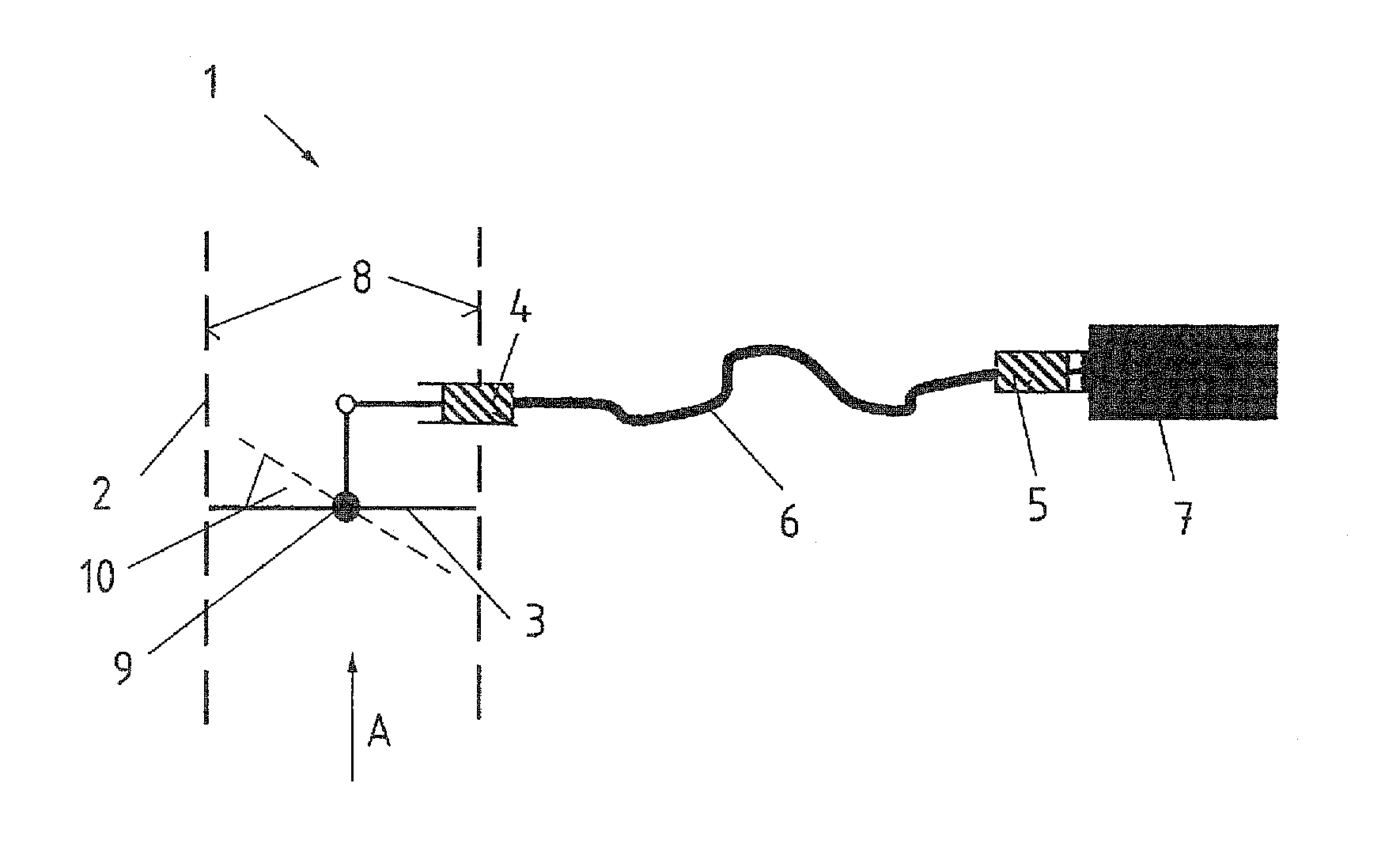
[0021] FIG. 1 is a schematic illustration of a flap arrangement according to the present invention; and
[0022] FIG. 2 is a schematic illustration of an exhaust flap of the flap arrangement in an exhaust track.
DETAILED DESCRIPTION OF PREFERRED EMBODIMENTS
[0023] Throughout all the figures, same or corresponding elements may generally be indicated by same reference numerals. These depicted embodiments are to be understood as illustrative of the invention and not as limiting in any way. It should also be understood that the figures are not necessarily to scale and that the embodiments are sometimes illustrated by graphic symbols, phantom lines, diagrammatic representations and fragmentary views. In certain instances, details which are not necessary for an understanding of the present invention or which render other details difficult to perceive may have been omitted.
[0024] Turning now to the drawing, and in particular to FIG. 1, there is shown a schematic illustration of a flap arrangement according to the present invention, generally designated by reference numeral 1 and arranged at an exhaust track 2 of a motor vehicle. The flap arrangement 1 has an exhaust flap 3 in the exhaust track 2 and is controlled via a slave cylinder 4. The slave cylinder 4 is connected with a master cylinder 5 via a hydraulic line 6. The master cylinder 5 is coupled with an adjusting actuator 7. A movement of the adjusting actuator 7 is thus transmitted onto the master cylinder 5 which in turn transmits its movement via the hydraulic line 6 onto the slave cylinder 4. The exhaust flap 3 completely closes in its "closed" position the exhaust track 2 by fully flatly bearing upon an inner contour 8 of the exhaust track 2. The exhaust flap 3 is mechanically coupled with the slave cylinder 4 so that the movement of the slave cylinder 4 is converted in a rotation of the exhaust flap 3 about a rotation axis 9 in the illustrated non-limiting embodiment. Rotating the exhaust flap 3 results in an open position at an angle 10 so that exhaust A can flow through the exhaust track 2.
[0025] FIG. 2 shows a simplified sectional view of the exhaust track 2. In the illustrated viewing direction, the exhaust flap 3 is shown in a "closed" position to seal off the exhaust track 2 because the outer shape of the exhaust flap 3 conforms to the inner contour 8 of the exhaust track 2. A movement of the slave cylinder 4 (not shown in FIG. 2), causes a rotation of the exhaust flap 3 about the rotation axis 9. The operative position is hereby at an angle which can be detected by a sensor 11.
[0026] While the invention has been illustrated and described in connection with currently preferred embodiments shown and described in detail, it is not intended to be limited to the details shown since various modifications and structural changes may be made without departing in any way from the spirit and scope of the present invention. The embodiments were chosen and described in order to explain the principles of the invention and practical application to thereby enable a person skilled in the art to best utilize the invention and various embodiments with various modifications as are suited to the particular use contemplated.
[0027] What is claimed as new and desired to be protected by Letters Patent is set forth in the appended claims and includes equivalents of the elements recited therein:
* * * * *
D00000
D00001
XML
uspto.report is an independent third-party trademark research tool that is not affiliated, endorsed, or sponsored by the United States Patent and Trademark Office (USPTO) or any other governmental organization. The information provided by uspto.report is based on publicly available data at the time of writing and is intended for informational purposes only.
While we strive to provide accurate and up-to-date information, we do not guarantee the accuracy, completeness, reliability, or suitability of the information displayed on this site. The use of this site is at your own risk. Any reliance you place on such information is therefore strictly at your own risk.
All official trademark data, including owner information, should be verified by visiting the official USPTO website at www.uspto.gov. This site is not intended to replace professional legal advice and should not be used as a substitute for consulting with a legal professional who is knowledgeable about trademark law.