Solar Roofing System And Method Of Installing The Same
Farmer; Franklin D. ; et al.
U.S. patent application number 13/167908 was filed with the patent office on 2011-12-29 for solar roofing system and method of installing the same. This patent application is currently assigned to AMERICAN ECOENERGY, INC.. Invention is credited to John Carter, Franklin D. Farmer, Daniel C. Lane.
| Application Number | 20110314753 13/167908 |
| Document ID | / |
| Family ID | 45351185 |
| Filed Date | 2011-12-29 |

| United States Patent Application | 20110314753 |
| Kind Code | A1 |
| Farmer; Franklin D. ; et al. | December 29, 2011 |
SOLAR ROOFING SYSTEM AND METHOD OF INSTALLING THE SAME
Abstract
A solar roofing system wherein the solar panels are integrated into the existing roof of a building in a watertight fashion, through the use of a starter trim piece, side step flashing pieces which are installed under each course of shingles such that they overlap to form a barrier along the side; a step flashing cover which seals the step flashing with the left and right sides of the solar panels, a Z-cleat that is fastened and sealed to the top of each solar panel, and a hood flashing which attaches to the Z-cleat and provides a sealed, watertight transition to the regular roofing material. The solar roofing system is watertight, and integrated with the actual roof, such that it does not need to be replaced when the roofing is replaced.
| Inventors: | Farmer; Franklin D.; (Flushing, MI) ; Carter; John; (Montrose, MI) ; Lane; Daniel C.; (Holt, MI) |
| Assignee: | AMERICAN ECOENERGY, INC. Flint MI |
| Family ID: | 45351185 |
| Appl. No.: | 13/167908 |
| Filed: | June 24, 2011 |
Related U.S. Patent Documents
| Application Number | Filing Date | Patent Number | ||
|---|---|---|---|---|
| 61358241 | Jun 24, 2010 | |||
| Current U.S. Class: | 52/173.3 ; 52/745.21 |
| Current CPC Class: | Y02B 10/20 20130101; F24S 25/40 20180501; F24S 2025/014 20180501; F24S 20/67 20180501; Y02E 10/44 20130101; Y02E 10/50 20130101; H02S 20/23 20141201; Y02B 10/10 20130101; Y02A 30/60 20180101; Y02E 10/47 20130101 |
| Class at Publication: | 52/173.3 ; 52/745.21 |
| International Class: | E04D 13/18 20060101 E04D013/18; E04B 1/38 20060101 E04B001/38 |
Claims
1. A solar roof assembly, comprising: a panel comprising at least one solar energy collector unit; and a plurality of trim elements to attach the panel to a support surface, wherein the plurality of trim elements permit water-tight integration of the panel with an asphalt-shingled roof, such that the solar roof assembly does not require removal or replacement when the asphalt-shingled roof is replaced.
2. A solar roof assembly for installation on a support surface, comprising: at least one panel, said panel having a main body with a solar energy collector unit thereon, two upwardly directed flanges on opposing lateral sides of the main body, and a top edge; a cleat having a bottom surface, a top surface and a wall therebetween, said bottom surface affixed to the main body between the two upwardly directed flanges, near the top edge of the panel; and a hood, which has a bend along its length which is generally aligned with the top edge of the at least one panel, said hood having an upper portion above the bend which is fastened to the support surface, and a lower portion below the bend extending from the support surface past the top edge of the at least one panel and affixed to the top surface of the cleat.
3. The solar roof assembly of claim 2, further comprising: electrical wiring components electrically connected to the solar energy collecting unit; wherein the electrical wiring components are enclosed between the main body of the panel, the cleat and the hood.
4. The solar roof assembly of claim 3, wherein a row of shingles is installed over the upper portion of the hood, to provide a watertight transition from the support surface to the solar roof assembly.
5. The solar roof assembly of claim 4, further comprising a first panel and a second panel, wherein the first and second panels are placed adjacent to one another along their lateral sides.
6. The solar roof assembly of claim 5, wherein the panels have interlocking features on adjacent upwardly directed flanges.
7. The solar roof assembly of claim 6, wherein the interlocking features comprise an upwardly directed flange having a protrusion on the first panel and the adjacent upwardly directed flange on the second panel being a generally U-shaped flange with an interiorly wrapped lip, wherein the U-shaped flange fits over the upwardly directed flange with the protrusion, and the interiorly wrapped lip engages the protrusion.
8. The solar roof assembly of claim 7, further comprising: clips to secure each panel to the support structure, said clips comprising a base which is attached to the support structure and a hook which fits over the upwardly directed flange.
9. The solar roof assembly of claim 8, wherein the first panel is secured to the support structure using clips along each lateral side, and the U-shaped flange of the second panel fits over the upwardly directed flange of the first panel and the clips, and the second panel is secured to the support surface using clips along the lateral side which is not adjacent to the first panel.
10. The solar roof assembly of claim 2, wherein a foam backing and an underlayment are attached to the support surface beneath the panels.
11. The solar roof assembly of claim 2, for application to a support surface with a covering of flexible shingles, further comprising: A panel assembly, comprising the at least one panel, said panel assembly having a first side with a first upwardly directed flange thereon, a second side with a second upwardly directed flange thereon, and a bottom; A first slit in the covering of flexible shingles adjacent to the first side of the panel assembly and a second slit in the covering of flexible shingles adjacent to the second side of the panel assembly; a starter trim piece, having a cleat for the attachment of the bottom of the panel assembly; a first plurality of side step flashing pieces, wherein each side step flashing piece comprises an L-shaped piece with a first leg which fits under the shingles adjacent to the first side of the panel assembly and a second leg which extends through the first slit and is adjacent to the first upwardly directed flange, and wherein the side step flashing pieces are overlapping along the first side of the panel assembly; a second plurality of side step flashing pieces, wherein each side step flashing piece comprises an L-shaped piece with a first leg which fits under the shingles adjacent to the second side of the panel assembly and a second leg which extends through the second slit and is adjacent to the second upwardly directed flange, and wherein the side step flashing pieces are overlapping along the second side of the panel assembly; a first side step flashing cap, having an inverted "u" shape which fits over the first plurality of overlapping side step flashing pieces and the adjacent first upwardly directed flange; and a second side step flashing cap, having an inverted "u" shape which fits over the second plurality of overlapping side step flashing pieces and the adjacent second upwardly directed flange.
12. The solar roof assembly of claim 2, for application to a support surface, further comprising: a panel assembly, comprising the at least one panel, said panel assembly having a first side with a first upwardly directed flange thereon, a second side with a second upwardly directed flange thereon, and a bottom; a starter trim piece, having a cleat for the attachment of the panel assembly and a cleat for attachment to a row of shingles; a first lineal side channel, comprising a two-layered back section with an opening along the bottom thereof which fits over the first upwardly directed flange of the panel assembly, a bottom leg which lies generally flush with the support surface, and a top leg which extends generally parallel with the bottom leg and is at a level sufficient to allow adjacent shingles to be installed under the top leg; and A second lineal side channel, comprising a two-layered back section with an opening along the bottom thereof which fits over the second upwardly directed flange of the panel assembly, a bottom leg which lies generally flush with the support surface, and a top leg which extends generally parallel with the bottom leg and is at a level sufficient to allow adjacent shingles to be installed under the top leg.
13. A kit for installing a solar roof assembly, comprising: a plurality of panels, each having a main body with a solar energy collecting unit thereon and two upwardly directed flanges extending therefrom, wherein each of the plurality of panels has features to interlock with adjacent panels; a starter trim piece, having a cleat for the attachment of panels; a cleat for the top of each panel; a hood; and electrical wiring components to link the solar collecting unit to an electrical grid.
14. The kit for installing a solar roof assembly of claim 13, further comprising: a plurality of side step flashing pieces; and two side step flashing caps which fit over the side step flashing pieces and the upwardly directed flange of the panels on the lateral edges of the solar roof assembly.
15. The kit for installing a solar roof assembly of claim 13, further comprising: two lineal side channels; a foam backing layer; and an underlayment for layering between the foam backing and the panels.
16. A method of installing a solar roof assembly on a support surface, comprising the steps of: positioning at least one panel on the support surface, the at least one panel having a main body with a solar energy collecting unit thereon and two upwardly-directed flanges extending therefrom on opposing lateral sides of the main body, and a top edge; fastening a cleat having a bottom surface, top surface and a wall therebetween, to the main body near the top edge thereof, so that the bottom surface is securely attached to the main body between the upwardly directed flanges, above the solar energy collecting unit; electrically connecting electrical connectors for the solar energy collecting units and feeding the electrical connectors through the support surface above the cleats; attaching an upper portion of a hood to the support surface above the top edge of the at least one panel; and affixing a lower portion of the hood to the top surface of the cleat and the upwardly directed flanges.
17. The method of installing a solar roof assembly of claim 16, wherein there are at least three panels, further comprising the steps of: Fastening a starter trim piece to the support surface, the starter trim piece having a cleat for connection of the panels installing a starter panel on the starter trim piece; installing at least one intermediate panel adjacent to the starter panel; installing an end panel adjacent to the at least one intermediate panel, wherein the starter panel, intermediate panel and end panel have interlocking features as between the panels.
18. The method of installing a solar roof assembly of claim 16 on a support surface having a covering of flexible shingles, further comprising the steps of: slitting the shingles along each side of an installation site for the panels; and inserting a plurality of side step flashing pieces having an L-shaped cross section with a first leg and a second leg along the slit, with the first leg of each of the plurality of side step flashing pieces under a row of shingles and the second leg of each of the plurality of side step flashing pieces positioned adjacent to the upwardly directed flanges on the outer sides of the at least one panel; and installing a side step flashing cap over the second legs and the upwardly directed flange.
19. The method of installing a solar roof assembly of claim 16, further comprising the steps of: laying one row of metal shingles; installing a starter trim piece above the row of metal shingles; and installing a first and second lineal side channel along the upwardly directed flanges of the at least one panel that are adjacent to the support surface.
20. A solar roof assembly, comprising: a plurality of panels laid side-by-side on a support surface, each panel comprising a main body with a solar energy collecting unit and two upwardly directed flanges wherein the flanges that are adjacent to another flange when the panels are laid side-by-side are adapted to interconnect with the flange of the adjacent panel in a water-tight fashion; a plurality of trim, flashing and cap elements to seal the bottom and the sides of the plurality of panels in a water-tight fashion; a cleat, installed between the upwardly directed flanges of each panel, having a bottom surface affixed to the main body, a top surface, and a wall therebetween; and a hood, having a top portion which is attached to the support surface above the panels, and a its bottom side which is attached to the top surfaces of the cleats and upwardly directed flanges, said hood having a row of shingles installed over the top portion to provide a water-tight seal.
Description
CROSS-REFERENCE TO RELATED APPLICATIONS
[0001] This is a continuing non-provisional application of co-pending United States provisional Patent Application Ser. No. 61/358,241, entitled SOLAR ROOFING SYSTEM AND METHOD OF INSTALLING THE SAME, and filed on 24 Jun. 2010, the disclosure of which is incorporated herein by reference.
STATEMENT REGARDING FEDERALLY SPONSORED RESEARCH OR DEVELOPMENT
[0002] Not applicable.
PARTIES TO A JOINT RESEARCH AGREEMENT
[0003] Not applicable.
REFERENCE TO A SEQUENCE LISTING
[0004] Not applicable.
BACKGROUND OF THE INVENTION
[0005] 1. Field of the Invention
[0006] The present invention relates to the field of solar panel systems and their installation on roofs or other support surfaces.
[0007] 2. Description of Related Art
[0008] Solar panels for installation on a roofing system to capture solar energy are known in the art. Traditional solar panel systems often included glass panels that were heavy, fragile and/or rigid, and traditional systems are often are difficult to install on an existing roof or must be moved when replacing shingles or other roofing materials. The solar roofing system described in this application, and the method of installing the same provides a light-weight, durable, flexible alternative to traditional glass-based solar panel systems, can be installed on existing shingled roofs in a water-tight manner, and does not have to be removed or replaced when re-roofing.
SUMMARY OF THE INVENTION
[0009] The invention includes a solar roofing system and a method for installing the same such that the solar roofing system as described herein can be installed on many types of roofs, including a roof that is cedar shake, slate, tile, asphalt shingle or metal, and therefore provides certain users, such as residential users, more options for the installation of a solar roofing system. The solar roofing system described herein can be applied on top of an existing traditional asphalt roof and the solar panels are an integrated part of the roofing so that the solar roofing system does not have to be replaced when the rest of the roofing is replaced.
BRIEF DESCRIPTION OF THE SEVERAL VIEW OF THE DRAWINGS
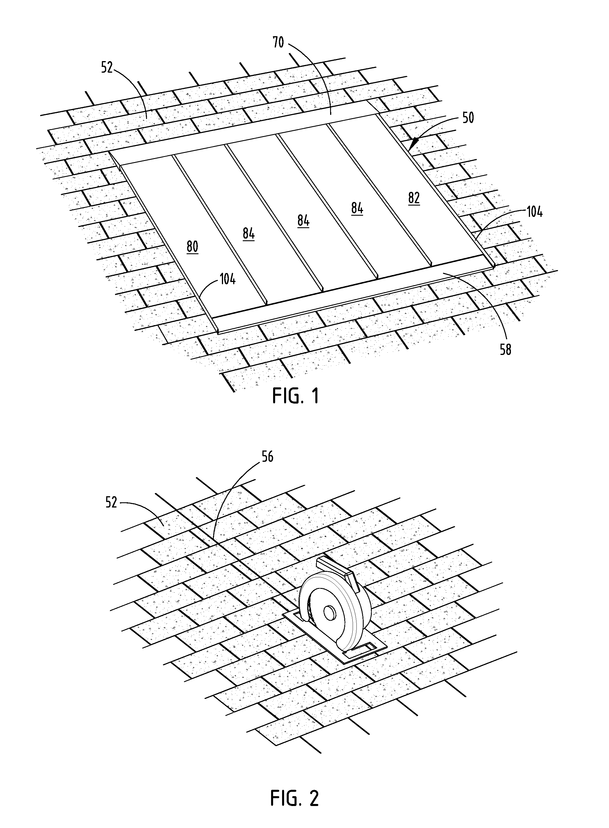
[0010] FIG. 1 is a perspective view of a solar roofing system;
[0011] FIG. 2 is a perspective view of a roof with a saw line, prepared for installation of the solar roofing system;
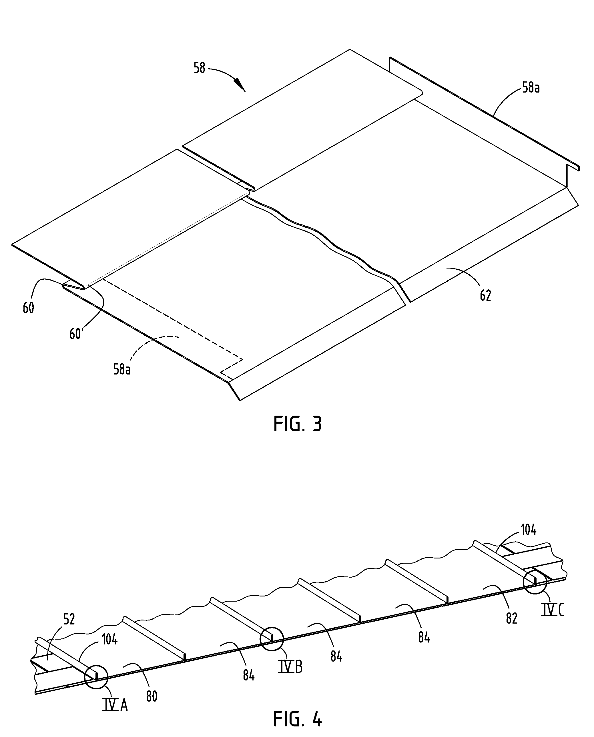
[0012] FIG. 3 is a perspective view of the starter trim;
[0013] FIG. 4 is a perspective cutaway view of the solar roof assembly;
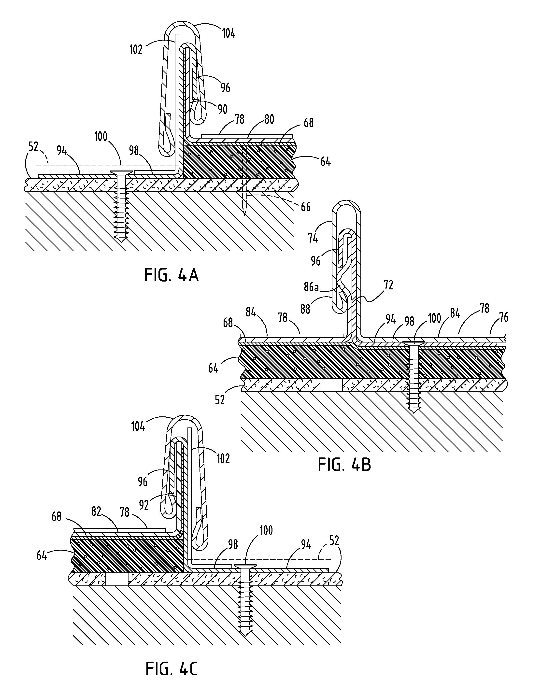
[0014] FIG. 4A is an enlarged end view of the section shown as IVA in FIG. 4;
[0015] FIG. 4B is an enlarged end view of the section shown as IVB in FIG. 4;
[0016] FIG. 4C is an enlarged end view of the section shown as IVC in FIG. 4;
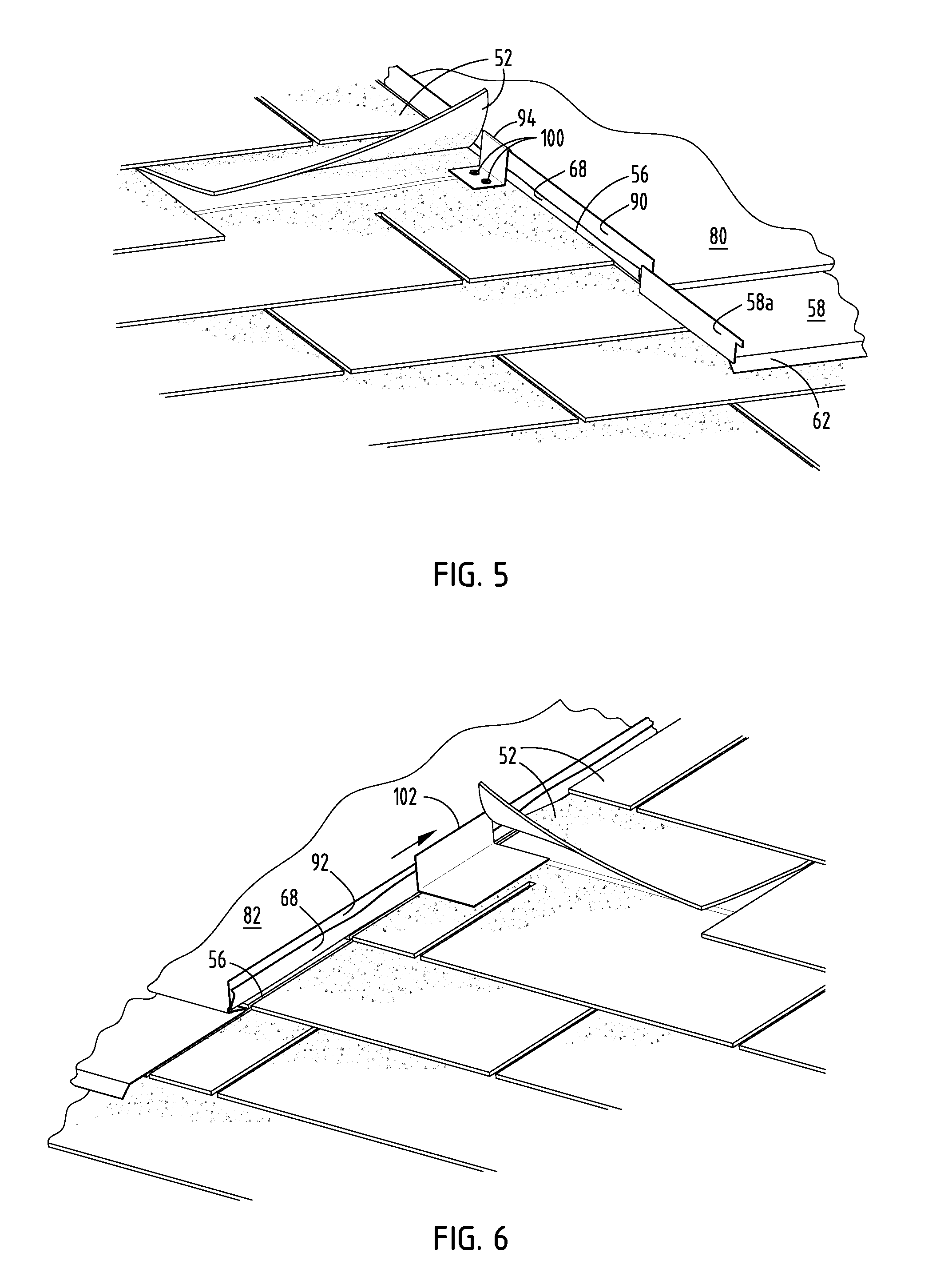
[0017] FIG. 5 is a perspective view of the starter panel as installed with clips;
[0018] FIG. 6 is a perspective view of the solar panel with the step flashing installed;
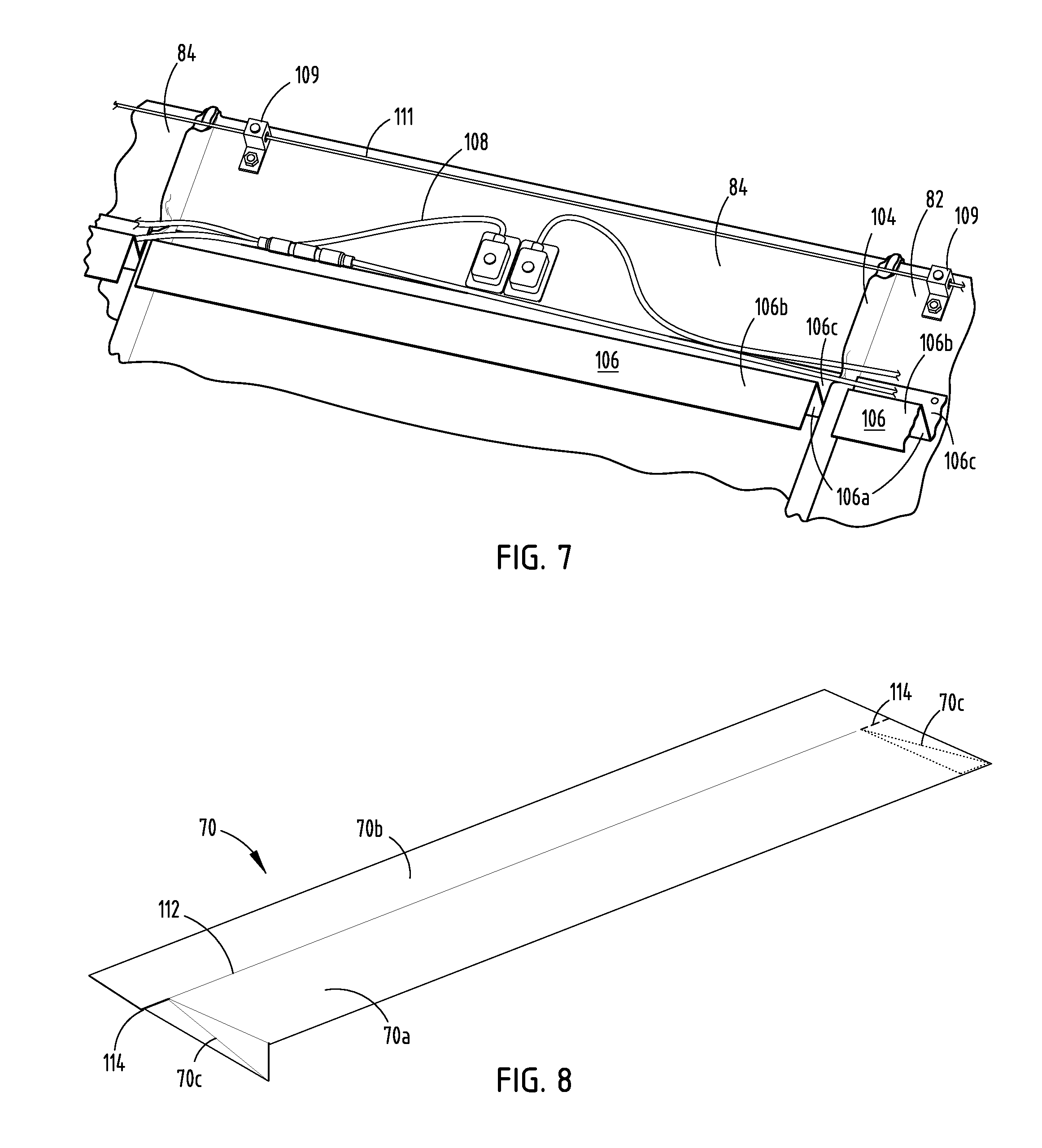
[0019] FIG. 7 is a perspective view of the solar panel with the step flashing, step flashing cap, and installed Z-cleat;
[0020] FIG. 8 is a perspective view of the hood flashing;
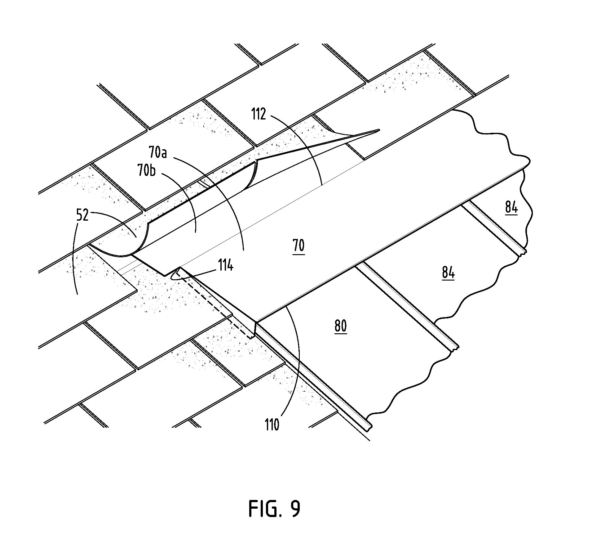
[0021] FIG. 9 is a perspective view of the hood flashing, as installed, with a partial row of shingles installed over the top portion;
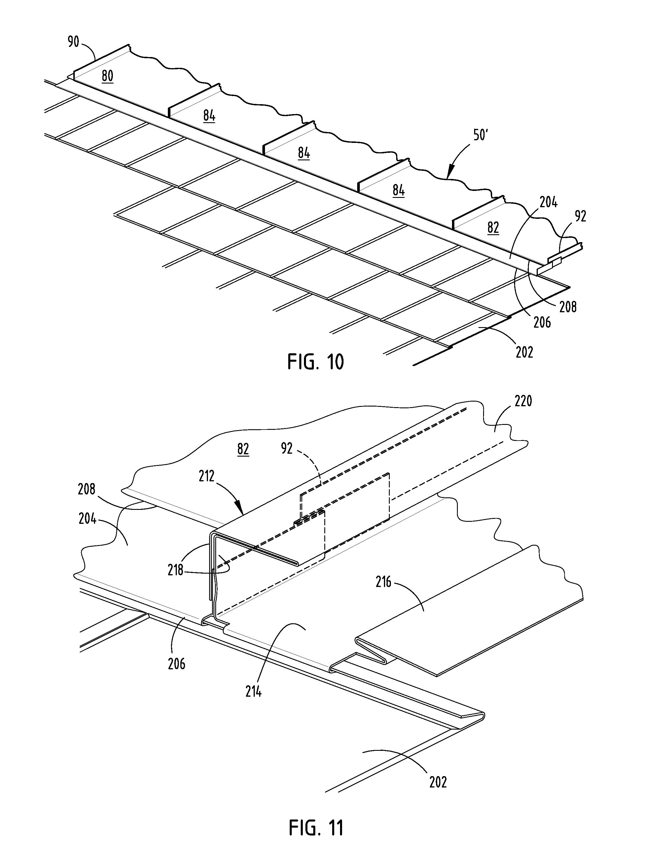
[0022] FIG. 10 is a perspective view of the metal starter trim used to install an embodiment of the solar roofing panel on a metal roof, as installed on a roof with one row of metal shingles;
[0023] FIG. 11 is an end view of the lineal side channel installed on the end panel; and
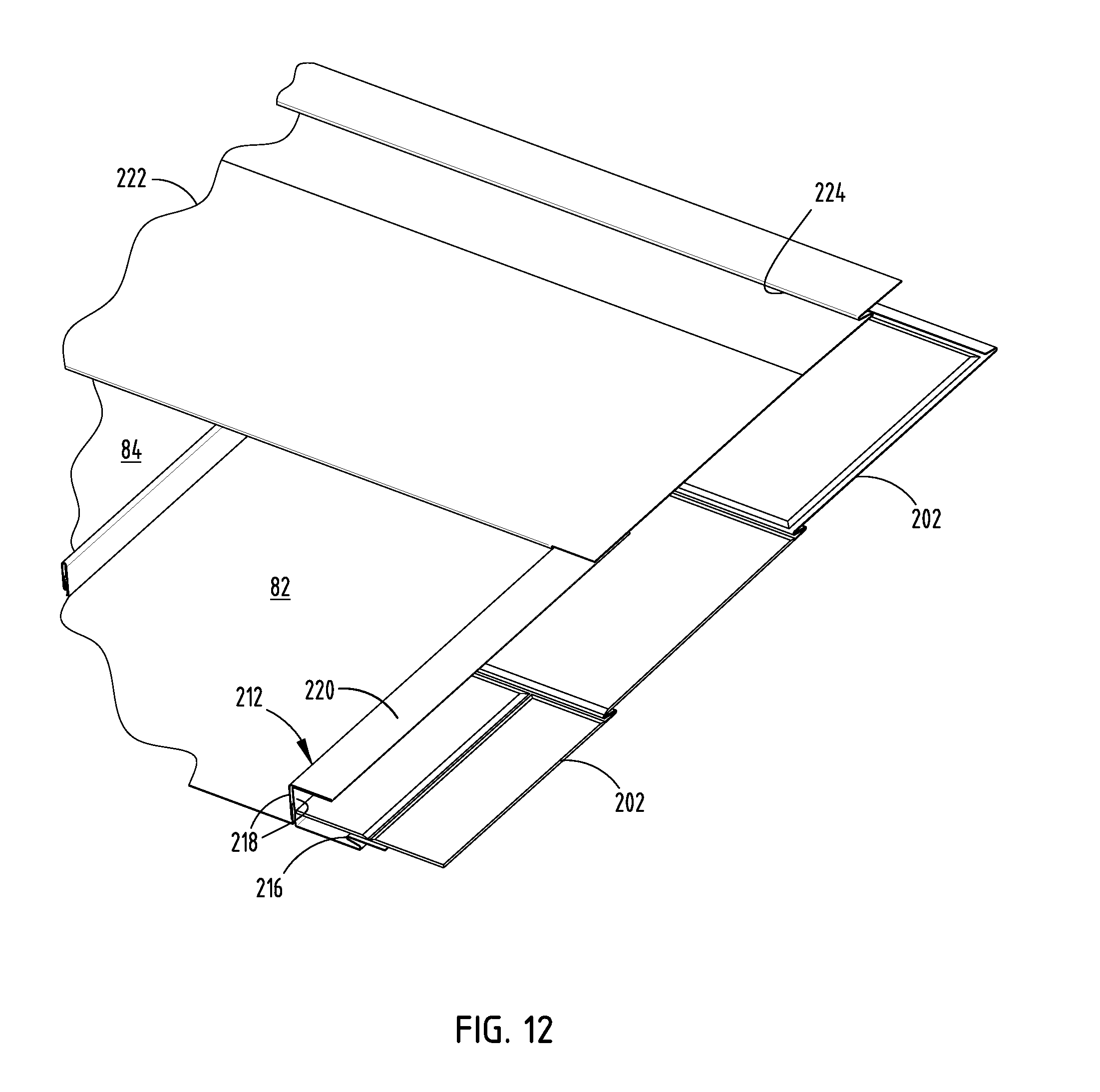
[0024] FIG. 12 is a perspective view of the hood transition, with a cutaway showing the z-cleat.
DESCRIPTION OF THE PREFERRED EMBODIMENTS
[0025] According to one preferred embodiment, the solar roofing system 50 can be applied over an existing asphalt shingle roof 52, a common residential roofing material (FIG. 1). Solar roofing system 50 comprises a plurality of interconnected solar panels 80, 82, 84 secured to and bounded along their bottom edges by a starter trim member 58 and secured to and bounded along their upper edges by hood flashing 70, which serves not only as an upper flashing, but also as a hood for covering the electrical wiring associated with solar panels 80, 82, 84 (FIG. 1). The panel on the left side of the array is starter panel 80, the panel on the right is end panel 82, and the intermediate panels are panels 84. The location of the solar roofing system 50 is preferably the portion of the roof 52 with the southern-most exposure and the most sun exposure, with no vent pipes or other roof protrusions (which may need to be moved to place the solar roofing in the location where it will most efficiently produce electricity).
[0026] The solar roofing system 50 can be installed so that it is as close as approximately twelve (12) inches from the existing starter row and as close as approximately twelve (12) inches from the ridge. The sides of the solar roofing system 50 may also be located as close as twelve (12) inches from the side wall or gable ends on the roof. The size of the solar roofing system 50 will be determined in accordance with known solar panel design principles and calculations based upon: (1) how much energy the end user uses; (2) the percentage of the end user's electrical needs that it desires to meet with the solar roofing system 50; (3) what zone the solar roofing system 50 will be installed in (to estimate the available solar energy); and (4) the amount and orientation of the end user's available roof space.
[0027] Once the location for the solar roofing system 50 is located, the surface of the roof 52 is prepared by removing any sharp protrusions such as nails, branches or other debris, and trimming or removing curled shingles to create a smooth base for the application of the of the solar roofing system 50.
[0028] To facilitate installation of a solar roofing system 50, the left and right sides of the installation site can optionally be marked using parallel vertical chalk lines. A circular saw or an equivalent can be used to make saw cuts 56 in the first layer of shingles on the roof along the vertical lines at the left and right sides of the installation site (FIG. 2). The length of the cuts is preferably between the length of the solar panels 80, 82, 84 that will be installed and a length which is less than six (6) inches longer than the solar panels 80, 82, 84. If any additional cutting is required, it can be accomplished using a utility knife or the like during the later installation phases of the flashing next to the panels 80 or 82. Saw cuts 56 allow an installer to lift the cut shingles and slide side fasteners and flashing under the cut shingles.
[0029] The starter trim 58 is preferably formed of sheet metal. It is installed along the bottom edge of the installation site (FIG. 1). The starter trim 58 can be provided "pre-trimmed," or can be cut to fit the width of the solar roofing system. The starter trim 58 has a downwardly extending starter trim cleat 60 on the top portion of the starter trim 58 and, preferably, an angled portion 62 along the bottom edge (to extend back toward the existing roof), more preferably a section which angles back at approximately forty degrees (40.degree.) (FIG. 3). Starter trim 58 is cut so that it extends beyond each side edge of the roofing system 50 to be installed, a distance approximately equal to the height of the left side flange 90 of left side solar panel 80 and right side flange 92 of right side solar panel 82. A short rectangular portion is cut from each of the upper corners of starter trim 58 from the top edge to a point at the root 60' of starter trim cleat 60. The remaining portion of each end of starter trim 58 which extends beyond the width of the roofing system 50 is folded up to define an upwardly extending flange 58a, which is approximately the same height as the aforesaid outside flanges on solar panels 80 and 82 (FIGS. 1, 3). Starter trim 58 is then placed so that its upper portion is positioned between cuts 56, and it is nailed in place above cleat 60.
[0030] A layer of foam backing 64 is applied to the installation site, starting at the left saw line 56 and extending to the right saw line 56 (FIGS. 4, 4A, 4B, 4C). It is positioned so that it overlaps the upper portion of starter trim 58, but not so far as to overlap cleat 60. Foam backing 64 extends upward to the top edge of where the hood flashing 70 will be installed. The foam backing 64, which is preferably approximately one quarter inch (1/4'') thick, can be of any type which is generally commercially available, such as fan-fold foam backing which is traditionally used for layering under siding. The foam backing 64 is preferably installed with plastic, flat-topped nails 66, with such flat-topped nails 66 preferably spaced at twenty-four (24) inch on-center intervals. The foam backing 64 can be permitted to extend beyond the right saw line 56 during the following installation steps until just before the flashing on the right side is installed.
[0031] Once the foam backing 64 is installed, it is covered with a layer of underlayment material 68, with the underlayment 68 extending beyond the left saw line 56, preferably for a distance which is approximately equal to the height of the raised side of the panel 80, most preferably approximately one (1) inch, and with the underlayment 68 extending from the bottom edge of foam layer 64 upward to a position which will be under where the hood 70 will be installed as described herein. The underlayment 68 can extend beyond these boundaries as applied, and be trimmed with a trim knife after or as the various components are installed over it. The underlayment 68 is fastened using nails spaced at twelve (12) inch on-center intervals, with laps nailed every six (6) inches. The right edge of the underlayment 68 (like the foam backing 64) can be trimmed just before the flashing on the right side is installed, and will also be trimmed to extend beyond the right saw line 56 a distance approximately equal to the height of the raised left side of the panel 82, preferably about one (1) inch past the right saw line 56.
[0032] Once the foam backing 64 and underlayment 68 are installed, the panels 80, 82, 84 can be installed over the underlayment 68. Each panel 80, 82, 84 comprises a rectangular metal frame, with a raised right side or flange 72 and raised left side or flange 74 (FIG. 4B). The flat base area 76 is covered with a flexible photovoltaic laminate 78, preferably a flexible and durable laminate such as that provided by United Solar Ovonic under the UNI-SOLAR brand. The photovoltaic laminate 78 does not extend all of the way to the top of the panels 80, 82, 84 or its sides, and sufficient space is left on the panels 80, 82, 84 to allow for the hood flashing 70 and other fastening items that are used to attach the panels to the roof, as further described herein.
[0033] Each set of panels to be used will include two outer panels (a starter panel 80 and an end panel 82), and a varying number of interior panels 84, as required to create an overall solar roofing system 50 of the desired size (FIG. 1). In a system designed to be installed from left to right, each interior panel 84 will have raised right flange 72 which is bent upwardly, preferably at an angle of approximately ninety degrees (90.degree.) (FIGS. 4, 4A, 4B, 4C). The raised right flange 72 is further characterized by a protrusion 86 facing the photovoltaic laminate 78. Each interior panel 84 will have a raised left side 74 comprising an inverted "U-shaped" member designed to fit and lock over the adjacent panel's right side flange 72. The outer leg of the inverted "U" extends down toward the photovoltaic laminate 78 of the adjacent panel 84, and terminates at an interiorly wrapped lip 88 which engages the protrusion 86 on the raised right edge flange 72 of the adjacent panel 84.
[0034] For a solar roofing system 50 that is to be installed from left to right, the starter panel 80 will have a right side flange 72a that is substantially the same as an interior panel's right side flange 72, but the starter panel left side is preferably a straight flange 90 (FIG. 4A). Similarly, the end panel 82 will have a left side flange 74a that is substantially the same as an interior panel's left side flange 74, but the right side of the end panel is preferably a straight flange 92 which is bent upwards from the base of the panel (FIG. 4C). Preferably, particularly when provided in "kit" form, the starter panel and end panel will be marked on the back side, or otherwise identified before delivery for ease of installation.
[0035] To install the starter panel 80, the starter panel 80 is positioned so that it is immediately to the inside of the portion of the starter trim 58 that was bent upwards, with the bottom edge of the starter panel 80 hooked around the starter trim cleat 60, and a screw is inserted through the top of the panel 80 (above the photovoltaic laminate 78 on the panel 80) to prevent the panel 80 from sliding downward. The underlayment 68 is folded upwards along the straight raised edge flange 90 on the left side of the starter panel 80, and trimmed as necessary. Clips 94 are then fastened at intervals along the raised left side flange 90 and right side flange 72 of the starter panel 80 (FIG. 5), preferably at twenty-four (24) inch on-center intervals, to secure the panel 80 to the existing roofing 52. The clips 94 have a U-shaped portion 96 that fits over the straight raised edge flange 90 of the starter panel 80 and the right side of the starter panel 80 with the protrusion 86, and a tab 98 that extends laterally at approximately a ninety degree (90.degree.) angle from the U-shaped portion 96, such that it rests flush against the existing roof 52. Preferably, two (2) screws 100 are used to fasten the tab 98 of each clip 94 to the roof 52 to provide maximum stability and wind resistance. For the clips 94 that are fastened on the left side of the starter panel 80, the course of shingles next to each clip 94 is folded upwards, and the clip 94 is fastened into the roof 52 below the shingle, so that the clips 94 and the screws 100 that they are attached with are covered by the shingle when it is in its normal position.
[0036] The interior panel 84 immediately to the right of the starter panel 80 is installed by sliding the U-shaped left side 74 of the panel 84 over the right side flange 72 of the starter panel 80, such that the U-shaped left side 74 is locked onto the protrusion 86 on the right side of the starter panel 80. Clips 94 are then fastened at intervals along the raised right side 72 of the interior panel 84, preferably at twenty-four (24) inch intervals, to fasten the right side of the panel 84 to the roof 52. To ensure that there is no damage to the next panel 84, the screws 100 should be tightened down so that they are flat and will not protrude into the neighboring panel 84. Subsequent panels 84 are installed by repeating this process, and sliding the U-shaped left side 74 of each panel 84 over the right side 72 of the previously installed panel 84, and then fastening the right side 72 of each panel with clips 94, preferably spaced at twenty-four (24) inch intervals.
[0037] To install the end panel 82, its U-shaped left side 74 is slid over the right side 72 of the neighboring panel 84, and the raised right flange 92 of the end panel 82 will line up with the second saw line 56 in the roofing 52. The foam backing 64 and the underlayment 68 can be trimmed and then the clips 94 are installed on the straight right edge 92 of the end panel 82, with the tabs 98 inserted and fastened underneath the neighboring course of shingles in the same manner as those on the left side of the starter panel 80.
[0038] Once the panels 80, 82, 84 are fastened to the existing roof 52, L-shaped step flashing segments 102 are installed on the left side of the starter panel 80 and the right side of the end panel 82 by sliding each piece of step flashing 102 up under a course of shingles, such that one leg of the "L" is below the shingle, and the other leg is flush with the straight side flange 90 of the starter panel 80 or the straight side flange 92 of end panel 82 (FIG. 6). Each flashing segment 102 has a width approximately the same as that of a shingle, and succeeding segments 102 are arranged in overlapping fashion as one proceeds from the top to the bottom of the solar roofing system 50. Once overlapping step flashing 102 is installed along the entire length of the starter panel 80 and end panel 82, a U-shaped step flashing clips can optionally be installed over the step flashing and the raised edge flange 90 or 92 of the panel 80 or 82. Then, a U-shaped step flashing cap, 104 with interiorly wrapped lips on each side of the "U" (FIG. 7) is placed over the step flashing 102 and the raised straight sides 90 and 92 of the starter panel 80 and end panel 82, by starting the step flashing cap 104 at the top, and forcing it down along the flanges 90 and 92 and the step flashing 102. Zip screws or similar fastening devices are then fastened, preferably at twenty-four (24) inch intervals along the length of the step flashing cap
[0039] Lengths of Z-cleat 106 having a vertical leg 106a and oppositely extending top and bottom legs 106b and 106c are installed across the top of each of the panels 80, 82, 84, preferably at a distance of approximately three (3) inches from the top of each panel 80, 82, 84, and above the top edge of the photovoltaic laminate 78 (FIG. 7). Z-cleat 106 is adhered to the panels 80, 82, 84 by placing a bead of sealant on the bottom of the flat surface 106c and the sides of the Z-cleat 106 so that the Z-cleat 106 is sealed to the base area 76 of each panel 80, 82, 84 and the raised edges 72, 74 on each side thereof to form a water-tight barrier. Each Z-cleat 106 has a length which is able to fit snugly within the raised edges of each panel 80, 82, 84. A screw or similar fastening device is installed on the outside of each piece of Z-cleat 106, outside the photovoltaic laminate 78. The screws must be placed outside the photovoltaic laminate 78, because if they puncture the laminate 78 the laminate 78 will not function properly.
[0040] Once the Z-cleat 106 has been installed on the top of each panel 80, 82, 84, the wiring 108 associated with the photovoltaic layers 78 are connected in a daisy chain fashion. The wiring 108 of each panel 80, 82, 84 connecting to the one next to it, with a maximum of approximately 400 Volts per grouping, and then feeding the wires 108 through the roof 52 and into the attic or building through a hole drilled in the roof 52. Exceeding the maximum voltage will increase the risk of fire or system failure for the solar roofing system 50. Some examples of acceptable combinations of panels are shown below in Table 1.
TABLE-US-00001 TABLE 1 Electrical Connection of Solar Panels System Size Number of Panels String Order PVL 136 (Panel Length 18 feet) 1.3 KW 10 2 strings of 5 2.4 KW 18 3 strings of 6 3.2 KW 24 3 strings of 8 4.1 KW 30 3 strings of 10 5.4 KW 40 4 strings of 10 6.1 KW 45 5 strings of 9 PVL 68 (Panel Length 10 feet) 1.3 KW 20 2 strings of 10 2.4 KW 36 3 strings of 12 3.2 KW 48 3 strings of 16 4.1 KW 60 3 strings of 20 5.4 KW 80 4 strings of 20 6.1 KW 90 5 strings of 18
[0041] Each panel 80, 82, 84 is also equipped with a ground lug 109, which will be interconnected with a ground wire 111, which traditionally terminates at an existing ground bar in an inverter. One type of ground lug 109 which is preferable for use is a grounding lug with a stainless steel self-tap, such as the Ilsco grounding lug model GBL-4 DBT-14-10-32. As with the other wiring 108, the grounding lug 109 is fastened to the panels 80, 82, 84 above the photovoltaic layers 78, to avoid penetration of the photovoltaic layers 78.
[0042] After the panels 80, 82, 84 are wired through to the building, a hood flashing 70 is used to cover the wiring 108 and provide a waterproof covering for the solar roofing system 50 (FIGS. 8, 9). The hood flashing 70 is a generally rectangular shaped piece, with an end cleat 110 along one side that locks onto the top flange 106b of Z-cleat 106 and a bend 112 that extends along its length so that a portion 70a of the hood flashing 70 will begin at the raised height of the Z-cleat flange 106b and extend towards the roof 52, and the portion 70b on the other side of the bend 112 will lay flush against the roof 52 above the solar panels 80, 82, 84 (FIG. 8).
[0043] The hood flashing 70 is cut to the width of the combined solar panels 80, 82, 84 with overlap on each side sufficient to allow the hood flashing 70 to fold over the raised outer edges of the panels 80, 82. As shown in FIG. 8, a short cut 114 is then made on each of the right and left sides of the hood flashing 70 at bend 112, with a length that is approximately equal to the height of the raised edges on the outside of the starter panel 80 and the end panel 82. The outer edges of the lower portion 70a of the hood flashing 70 are then folded down on each side. A diagonal fold 70c is then made from the interior end of the short cut 114 to the outer edge of the folded hood flashing 70 (FIG. 9).
[0044] The hood flashing 70 is then installed so that end cleat 110 locks over the edge of Z-cleat flange 106b, and the triangles that were folded into each edge form seals along the left and right sides of the hood flashing 70. When installed, the top portion 70b of the hood flashing 70 is flush against the roof 52. To seal the top portion of the hood flashing 70 so that it is water tight, a course of shingles is installed over the hood flashing portion 70b, according to the shingle manufacturer's instructions, and another course of shingles is installed above and overlapping the course of shingles that is installed over the hood flashing 70 to ensure a water-tight seal (FIG. 9).
[0045] The panels 80, 82, 84, wiring 108, flashing and trim elements 58, 70, 102, 104, 106, clips 94, foam backing 64, underlayment 68 and various other elements as described in each embodiment may be supplied in pre-packaged kit form, to facilitate installation of the solar panel system 50 on a traditional roof 52 such that it is an integrated part of the roof 52. Selling the components of the solar roofing system 50 as a kit will also eliminate the need for the installer to separately calculate the number of solar panels 80, 82, 84 required, purchase parts and determine which parts will be suitable for use in combination with each other. The pre-packaged kits can preferably be prepared and packaged to meet certain desirable or commonly used system sizes for residential use, or for larger commercial uses, such as those shown in Table 1.
[0046] In another preferred embodiment, a metal solar roofing system 50' can be installed on a roof that will also have metal shingles 202 installed thereon (FIG. 10). However, when two different metals are in contact and subject to a corrosive or conductive environment (such as one that might be experienced on the roof of a building) a current flow may be initiated between the metals. Therefore, a non-absorbent insulating layer must be used between rows of dissimilar metals, preferably an insulating synthetic underlayment material. The method of installing a solar roofing system 50' is similar to that used to install the solar roofing system 50 on an asphalt shingle or other roof 52, although some modifications to the flashing elements are made to seal the solar roofing system 50' to the metal roof 202.
[0047] To install a solar roofing system 50' with metal shingles 202, at least one (1) row of the metal shingles 202 must be installed first. Then, the metal starter strip 204 is attached (FIG. 10). Starter strip has a shingle cleat 206 and a panel cleat 208. The shingle cleat 206 is at the bottom of the metal starter strip 204, and is used to hook over and thereby anchor the metal starter strip 204 to the metal shingles 202. The panel cleat 208 is along a midline of the metal starter strip 204, and is used to anchor the panels 80, 82, 84 to the metal starter strip 204, by hooking the bottom lip of panels 80, 82, 84 over cleat 208. Once the metal starter strip 204 is in place, the solar roofing panels 80, 82, 84 can be installed generally as described above with respect to the installation on an asphalt roof 52.
[0048] A lineal side channel 218, is used on each side of the solar roofing system 50' in place of the step flashing 102 and flashing cover 104 as described above (FIG. 11). The lineal side channel has three sections: (a) a bottom section 214, which lies flush with the roof and has a side cleat 216 to fasten adjacent metal shingles 202, (b) a two-layered back section 218, which is oriented perpendicular to the roof and has an opening from the bottom which is sized to fit over the straight raised edge flanges 90 and 92 of the starter and end panels 80 and 82, and (c) a top section 220, which extends outward from the metal solar roofing system 50 to fit over the adjacent metal shingles 202. On the left and right sides of the outside panels 80 and 82 the lineal side channel 212 is installed by sliding the back 218 over the straight raised left and right side flanges 90 and 92, such that the top 220 and bottom 214 of the lineal side channels 212 extend outwardly from the solar roofing system 50'. The lineal side channel 212 is cut to a length longer than the panels 80 or 82, such that it extends to the bottom of the metal starter trim 204 on each side, approximately three (3) inches below the raised side flange 90 or 92 of the panel 80 or 82 that is being capped. The lineal side channel 212 is fastened to the roof 202 by nailing through the bottom section 214 at intervals along its length.
[0049] Once the lineal side channel 212 is installed, metal shingles 202 can be installed along the sides of the solar roofing system 50, where they are inserted into the lineal side channel 212 (FIG. 11). A Z-cleat 106 is then installed on the top of each panel 80, 82, 84, and the panels are electrically connected as described above, with the wires routed down into the building. A metal hood transition piece 222 is then installed in the same manner as the hood flashing 70 described above (FIG. 12). The metal hood transition piece 222 is generally similar to the hood flashing 70 except that is has an additional transitional cleat 224 along the top for the installation of metal shingles 202, by hooking them over cleat 224. Metal shingles 202 can then be installed over the metal hood transition piece 222, with a bead of sealant placed at the lap of the shingle 202 and the metal hood transition piece 222. It may be necessary in some instances to install a siding starter on the metal hood transition piece 222 so that the shingles 202 line up evenly.
[0050] The elements of the embodiment of the solar roofing system 50' as described for use with metal roofing can also be supplied in pre-fabricated "kit" form, for ease and efficiency of installation of the solar roofing system 50', as described above with relation to solar roofing system 50.
[0051] It will be apparent to those skilled in the pertinent arts that still other embodiments of solar roofing assemblies in accordance with the invention can be designed, as well as variations to the method of installing the same. That is the principles of an assembly and method of installing it in accordance with the invention are not limited to the specific embodiments described herein. Accordingly, it will be apparent to those skilled in the art that modifications and other variations of the above-described illustrative embodiments of the invention may be effected without departing from the spirit and scope of the novel concepts of the invention.
* * * * *
D00000
D00001
D00002
D00003
D00004
D00005
D00006
D00007
D00008
XML
uspto.report is an independent third-party trademark research tool that is not affiliated, endorsed, or sponsored by the United States Patent and Trademark Office (USPTO) or any other governmental organization. The information provided by uspto.report is based on publicly available data at the time of writing and is intended for informational purposes only.
While we strive to provide accurate and up-to-date information, we do not guarantee the accuracy, completeness, reliability, or suitability of the information displayed on this site. The use of this site is at your own risk. Any reliance you place on such information is therefore strictly at your own risk.
All official trademark data, including owner information, should be verified by visiting the official USPTO website at www.uspto.gov. This site is not intended to replace professional legal advice and should not be used as a substitute for consulting with a legal professional who is knowledgeable about trademark law.