Rubber armored rifle scope with integrated external laser sight
Cheng; Carsen
U.S. patent application number 13/199468 was filed with the patent office on 2011-12-29 for rubber armored rifle scope with integrated external laser sight. Invention is credited to Carsen Cheng.
| Application Number | 20110314720 13/199468 |
| Document ID | / |
| Family ID | 45351169 |
| Filed Date | 2011-12-29 |


View All Diagrams
| United States Patent Application | 20110314720 |
| Kind Code | A1 |
| Cheng; Carsen | December 29, 2011 |
Rubber armored rifle scope with integrated external laser sight
Abstract
A laser sighting device includes a sighting scope, an objective lens, an ocular assembly, a laser locator, an illumination unit, and an operation switch, which is provided on the sighting scope to operate the telescopic sighting device at least between a laser mode and an illumination mode, wherein in the laser mode, the laser locator is arranged to generate a laser beam toward a target from an exterior of the sighting scope, wherein in the illumination mode, the illumination unit is arranged to generate illumination toward the objective lens from within the sighting scope so that a user is able to observe an illumination pointer through the ocular lens irrespective of whether the laser locator is activated.
| Inventors: | Cheng; Carsen; (City of Industry, CA) |
| Family ID: | 45351169 |
| Appl. No.: | 13/199468 |
| Filed: | August 30, 2011 |
Related U.S. Patent Documents
| Application Number | Filing Date | Patent Number | ||
|---|---|---|---|---|
| 12686352 | Jan 12, 2010 | |||
| 13199468 | ||||
| Current U.S. Class: | 42/117 |
| Current CPC Class: | F41G 1/35 20130101; F41G 11/003 20130101; F41G 1/345 20130101 |
| Class at Publication: | 42/117 |
| International Class: | F41G 1/00 20060101 F41G001/00; F41G 1/38 20060101 F41G001/38 |
Claims
1. A laser sighting device, comprising: a sighting scope defining a bell portion, a body portion and an eyepiece portion, wherein said sighting scope has a receiving cavity formed along said bell portion, said body portion and said eyepiece portion; an objective lens mounted at said bell portion of said sighting scope for focusing light at a focal point in said body portion of said sighting scope; an ocular assembly comprises an ocular lens provided at said eyepiece portion of said sighting scope for magnifying said light from said focal point; to a laser locator which is mounted at said body portion of said sighting scope, and comprises a laser emitter arranged to generate a laser beam toward a target; an illumination unit coupled with said ocular assembly and is arranged to selectively provide illumination toward said ocular assembly; and an operation switch provided on said sighting scope to operate said laser sighting device at least between a laser mode and an illumination mode, wherein in said laser mode, said laser locator is arranged to generate a laser beam toward a target from an exterior of said sighting scope, wherein in said illumination mode, said illumination unit is arranged to generate illumination toward said objective lens from within said sighting scope so that a user is able to observe an illumination pointer through said ocular lens irrespective of whether said laser locator is activated.
2. The laser sighting device, as recited in claim 1, wherein said laser locator further comprises an emitter housing mounted on top of said body portion of said sighting scope, wherein said laser emitter is received in said emitter housing for selectively generating a laser beam in front of said laser sighting device, so that said emitter housing is arranged to protect said laser emitter and mount said laser emitter on top of said sighting scope.
3. The laser sighting device, as recited in claim 2, wherein said illumination unit comprises an illumination housing mounted at a bottom portion of said body portion of said sighting scope, and a LED mounted in said illumination housing, wherein said LED is arranged to generate illumination toward said objective lens for illustrating an illumination dot on said ocular lens so as to assist said user to locate said target when said user sees through said ocular lens.
4. The laser sighting device, as recited in claim 3, wherein said illumination to unit further comprises an elevation adjustment knob operatively provided on a top surface of said body portion of said sighting scope and is connected with said LED for controlling an elevation of said illumination dot as seen through said ocular lens, wherein said elevation adjustment knob is capable of being rotated to adjust said elevation of said illumination dot.
5. The laser sighting device, as recited in claim 4, wherein said illumination unit further comprises an windage adjustment knob operatively provided on a side surface of said body portion of said sighting scope and is connected with said LED for controlling an windage movement of said illumination dot as seen through said ocular lens, wherein said elevation adjustment knob is capable of being rotated to adjust said windage of said illumination dot.
6. The laser sighting device, as recited in claim 4, wherein said illumination unit further comprises a plurality of protective caps removably coupled to said elevation adjustment knob and said windage adjustment knob respectively for normally protecting said elevation adjustment knob and said windage adjustment knob from exposing to ambient environment.
7. The laser sighting device, as recited in claim 5, wherein said illumination unit further comprises a plurality of protective caps removably coupled to said elevation adjustment knob and said windage adjustment knob respectively for normally protecting said elevation adjustment knob and said windage adjustment knob from exposing to ambient environment.
8. The laser sighting device, as recited in claim 6, wherein said operation switch is provided on a side surface of said body portion of said sighting scope and is arranged to switch said laser sighting device to operate between said laser mode and said illumination mode, wherein said operation switch comprises a rheostat knob rotatably mounted on said body portion of said sighting scope in such a manner that said rheostat knob is capable of rotating between eight predetermined positions.
9. The laser sighting device, as recited in claim 7, wherein said operation switch is provided on a side surface of said body portion of said sighting scope and is arranged to switch said laser sighting device to operate between said laser mode and said illumination mode, wherein said operation switch comprises a rheostat knob rotatably mounted on said body portion of said sighting scope in such a manner that said rheostat knob is capable of rotating between eight predetermined positions.
10. The laser sighting device, as recited in claim 8, wherein said at said first position of said rheostat knob, said rheostat knob is set to turn both said laser emitter and said LED off, wherein at said second position of said rheostat knob, said rheostat knob is set to turn on said laser emitter only, wherein at said third position of said rheostat knob, said rheostat knob is set to turn on said LED only with maximum brightness, wherein at said fourth position through said seventh position of said rheostat knob, said rheostat knob is set to turn on said LED only with differing brightness, said fourth position being the brightest among said fourth through seventh positions, while said seventh position being the darkest among said fourth through seventh positions, wherein at said eighth position, both of said laser emitter and said LED are turned on.
11. The laser sighting device, as recited in claim 9, wherein said at said first position of said rheostat knob, said rheostat knob is set to turn both said laser emitter and said LED off, wherein at said second position of said rheostat knob, said rheostat knob is set to turn on said laser emitter only, wherein at said third position of said rheostat knob, said rheostat knob is set to turn on said LED only with maximum brightness, wherein at said fourth position through said seventh position of said rheostat knob, said rheostat knob is set to turn on said LED only with differing brightness, said fourth position being the brightest among said fourth through seventh positions, while said seventh position being the darkest among said fourth through seventh positions, wherein at said eighth position, both of said laser emitter and said LED are turned on.
12. The laser sighting device, as recited in claim 10, wherein said laser dot and said illumination dot generated by said laser emitter and said LED respectively have different colors.
13. The laser sighting device, as recited in claim 11, wherein said laser dot and said illumination dot generated by said laser emitter and said LED respectively have different colors.
14. The laser sighting device, as recited in claim 12, wherein said illumination unit further comprises a reflective coating formed on an outer side of said objective lens, wherein said reflective coating is arranged to allow light from passing from inside said sighting scope to an exterior thereof.
15. The laser sighting device, as recited in claim 13, wherein said illumination unit further comprises a reflective coating formed on an outer side of said objective lens, wherein said reflective coating is arranged to allow light from passing from inside said sighting scope to an exterior thereof.
16. The laser sighting device, as recited in claim 14, further comprising a mounting arrangement provided at a bottom portion of said body portion of said sighting scope for mounting onto a firearm, wherein said mounting arrangement comprises a mounting rail extended along a bottom portion of said body portion of said sighting scope, wherein said mounting rail is arranged to mount onto a predetermined firearm.
17. The laser sighting device, as recited in claim 15, further comprising a mounting arrangement provided at a bottom portion of said body portion of said sighting scope for mounting onto a firearm, wherein said mounting arrangement comprises a mounting rail extended along a bottom portion of said body portion of said sighting scope, wherein said mounting rail is arranged to mount onto a predetermined firearm.
18. The laser sighting device, as recited in claim 13, further comprising a cap apparatus which comprises a plurality of protection covers and a plurality of cover links extended between said protection covers, wherein said cap apparatus is made of flexible materials and is shaped and size to allow said protection covers to mount on said front and said rear side of said sighting scope for normally protecting said ocular assembly and said objective lens respectively.
19. The laser sighting device, as recited in claim 15, further comprising a cap apparatus which comprises a plurality of protection covers and a plurality of cover links extended between said protection covers, wherein said cap apparatus is made of flexible materials and is shaped and size to allow said protection covers to mount on said front and said rear side of said sighting scope for normally protecting said ocular assembly and said objective lens respectively.
20. The laser sighting device, as recited in claim 17, further comprising a cap apparatus which comprises a plurality of protection covers and a plurality of cover links extended between said protection covers, wherein said cap apparatus is made of flexible materials and is shaped and size to allow said protection covers to mount on said front and said rear side of said sighting scope for normally protecting said ocular assembly and said objective lens respectively.
Description
CROSS REFERENCE OF RELATED APPLICATION
[0001] This is a Continuation-In-Part application of a non-provisional application having an application Ser. No. 12/686,352, filed Jan. 12, 2010.
BACKGROUND OF THE PRESENT INVENTION
[0002] 1. Field of Invention
[0003] This invention relates to sighting devices for firearms and more particularly to laser-assisted sights coupled with optical telescopes.
[0004] 2. Description of Related Arts
[0005] Laser sights and optical telescopes serve to improve the shooting accuracy of firearms. Telescopes have been developed to mount on a firearm to provide a shooter with better aim. To further enhance the experience in shooting a firearm, some mounted telescopes can be coupled with a laser sight to provide a shooter with an additional point of aim increase or enhance the accuracy of a shot.
[0006] In general, a laser sight is mounted onto a telescope as a separate detachable component of a scope. These types of laser sight attachments function independently of the telescope, requiring separate and additional batteries to power the laser and separate switches to turn the laser on and off.
[0007] Other scopes in the prior art may have the laser sight attached to the telescope. In this type of scope, the laser sighting component of the scope functions completely independently of the telescope requiring different and additional batteries for the laser component of the scope.
[0008] Due to the independent nature of laser sights that are detachable or permanently affixed to a telescope, aiming and shooting a firearm with these existing laser enhanced scopes is cumbersome with respect to the location of the laser, the detachable parts, and additional batteries adding to the bulk of the scope.
[0009] Accordingly, a need to improve the shooter experience with less cumbersome and bulky scopes exists. There is the need to streamline and make convenient the use of, including the control of the functions of a laser sight and optical scope.
SUMMARY OF THE PRESENT INVENTION
[0010] The invention is advantageous in that it provides a laser sight and an optical telescope as a single unit, wherein the laser sight assembly is attached to the optical telescope as a non-removable component of the scope.
[0011] Another advantage of the invention is provide a laser sighting apparatus, wherein the telescope portion of the device may include a reticle. Illumination of the laser and the reticle of the telescope may be powered by a single power source or battery and controlled by a single controller. The controller may be, for example, a rheostat knob. The rheostat knob may also control the simultaneous illumination of the laser and the reticle, the illumination of the laser only, and the illumination of the reticle only. The rheostat knob may also illuminate the reticle with five levels of brightness.
[0012] In another embodiment of the invention, the power source or battery of the device may be contained or housed within a controller, for example, a rheostat knob. This power source or battery provides the power to illuminate both the laser and the reticle of the scope.
[0013] There is disclosed an apparatus/device for laser sighting, the apparatus comprising a laser and a scope comprising a reticle, the laser and scope coupled together forming a single integrated unit, wherein the laser and the reticle are powered by a single power source, and illumination of said laser and said reticle are controlled by a single controller, according to an embodiment of the present invention.
[0014] There is further disclosed a mountable optical scope with external laser sighting according to an embodiment of the present invention in which, the optical scope with external laser sighting comprises a laser integrally coupled with the scope as a single unit, the laser being non-removable from the unit within an integrally connected laser housing. The scope with laser sighting according to the embodiment, further comprises a power source located next to the laser housing and electrically configured for powering the laser; a reticle located within the scope and illuminated by the power source, said reticle having at least two levels of brightness; and a single controller configured to control both the powering of the laser and illumination of the reticle, wherein the power source is housed within the controller.
[0015] There is also disclosed an apparatus for laser sighting according to an embodiment of the present invention in which, the apparatus comprises a laser coupled with a scope as a single unit, wherein the laser is a non-removable component of the unit, integrated to the side of the scope and powered by a power source, wherein the scope contains a reticle that is capable of illumination by the power source, said reticle having at least two levels of brightness.
[0016] Additional advantages and features of the invention will become apparent from the description which follows, and may be realized by means of the instrumentalities and combinations particular point out in the appended claims.
[0017] According to the present invention, the foregoing and other objects and advantages are attained by providing a laser sighting device, comprising:
[0018] a sighting scope defining a bell portion, a body portion and an eyepiece portion, wherein the sighting scope has a receiving cavity formed along the bell portion, the body portion and the eyepiece portion;
[0019] an objective lens mounted at the bell portion of the sighting scope for focusing light at a focal point in the body portion of the sighting scope;
[0020] an ocular assembly comprises an ocular lens provided at the eyepiece portion of the sighting scope for magnifying the light from the focal point;
[0021] a laser locator which is mounted at the body portion of the sighting scope, and comprises a laser emitter arranged to generate a laser beam toward a target;
[0022] an illumination unit coupled with the ocular assembly and is arranged to selectively provide illumination toward the ocular assembly; and
[0023] an operation switch provided on the sighting scope to operate the telescopic sighting device at least between a laser mode and an illumination mode, wherein in the laser mode, the laser locator is arranged to generate a laser beam toward a target from an exterior of the sighting scope, wherein in the illumination mode, the illumination unit is arranged to generate illumination toward the objective lens from within the sighting scope so that a user is able to observe an illumination pointer through the ocular lens irrespective of whether the laser locator is activated.
[0024] Still further objects and advantages will become apparent from a consideration of the ensuing description and drawings.
[0025] These and other objectives, features, and advantages of the present invention will become apparent from the following detailed description, the accompanying drawings, and the appended claims.
BRIEF DESCRIPTION OF THE DRAWINGS
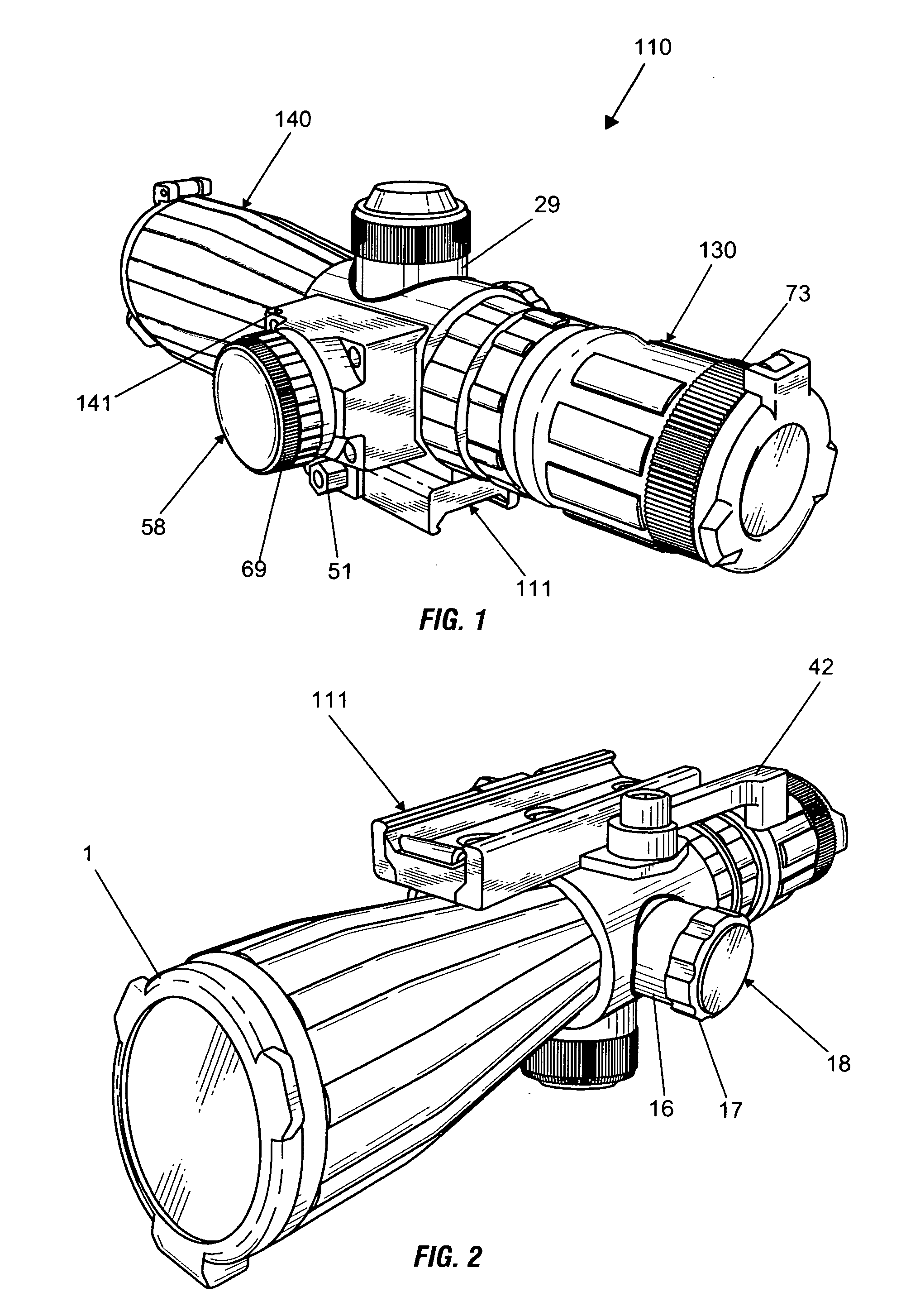
[0026] FIG. 1 is a top, left perspective view of a laser sighting device in accordance with an embodiment of the present invention.
[0027] FIG. 2 is a bottom, right perspective view of the laser sighting device of FIG. 1, according to an embodiment of the present invention.
[0028] FIG. 3 is a right side view of the laser sighting device of FIG. 1, according to embodiment of the present invention.
[0029] FIG. 4 is a left side view of the laser sighting device of FIG. 1, according to an embodiment of the present invention.
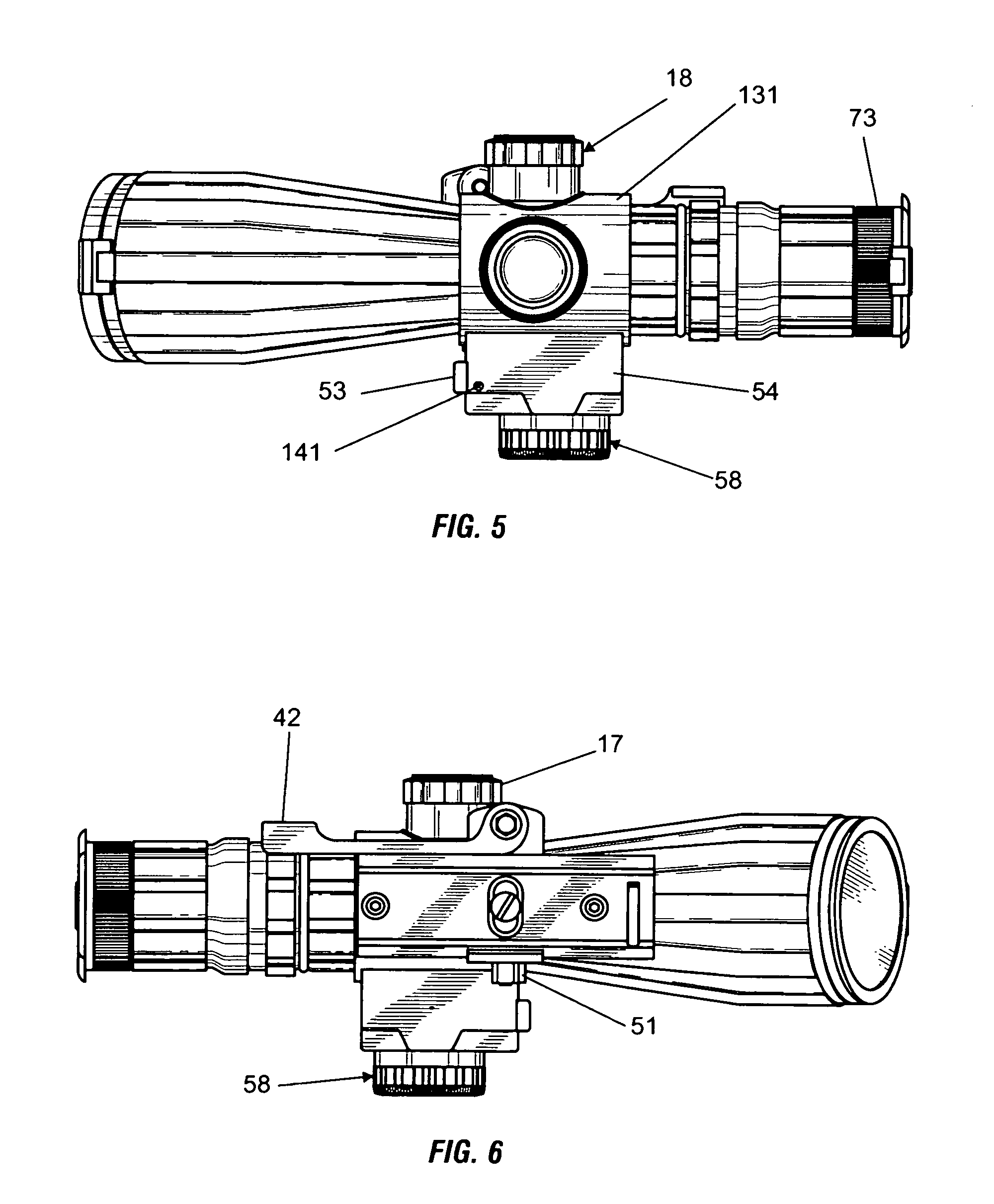
[0030] FIG. 5 is a top plan view of the laser sighting device of FIG. 1, according to an embodiment of the present invention.
[0031] FIG. 6 is a bottom plan view of the laser sighting device of FIG. 1 according to an embodiment of the present invention.
[0032] FIG. 7 is a front view of the laser sighting device of FIG. 1 according to an embodiment of the present invention.
[0033] FIG. 8 is a rear view of the laser sighting device of FIG. 1 according to an embodiment of the present invention.
[0034] FIG. 9 is another left side view of a laser sighting device according to an embodiment of the present invention.
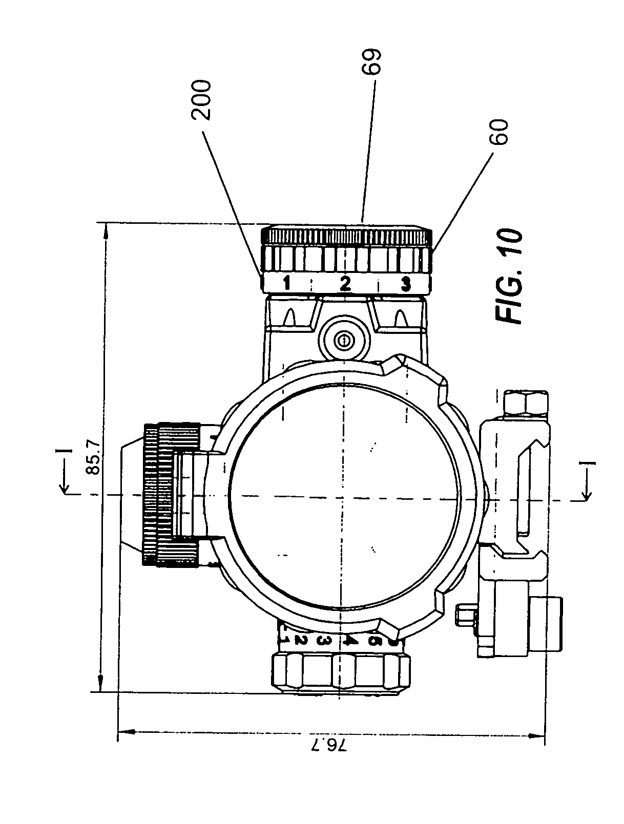
[0035] FIG. 10 is a front view of a laser sighting device according to an embodiment of the present invention.
[0036] FIG. 11 is a cross sectional side view along the I-I line of FIG. 10 of a laser sighting device according to an embodiment of the present invention.
[0037] FIG. 12 is a cross sectional top view along the II-II line of FIG. 9 of a laser sighting device according to an embodiment of the present invention.
[0038] FIG. 13 is a cross sectional perspective view of the rheostat knob of the laser sighting device according to an embodiment of the present invention.
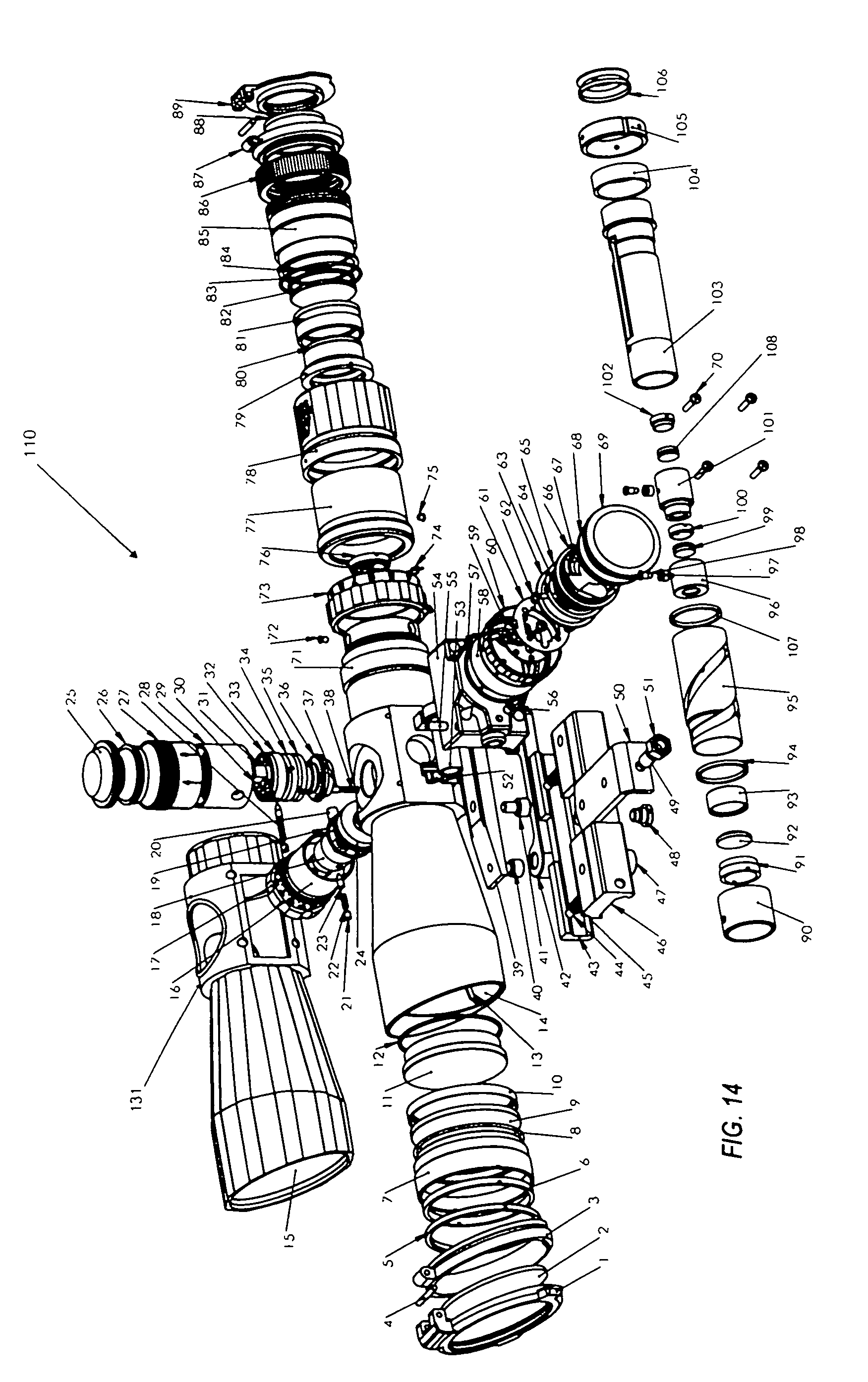
[0039] FIG. 14 is an exploded view of a laser sighting device accordingly to an embodiment of the present invention.
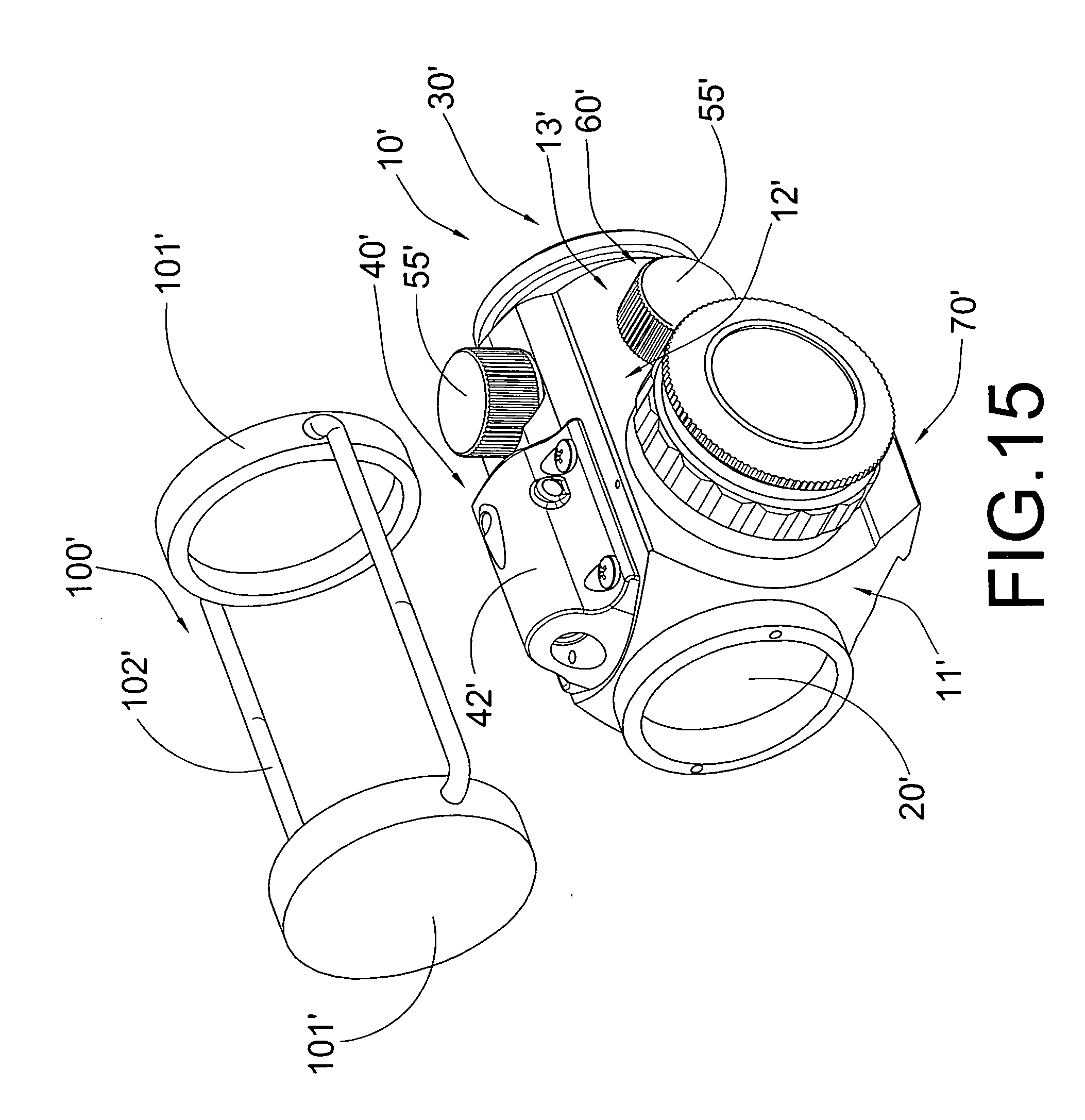
[0040] FIG. 15 is a perspective view of a laser sighting device according to a second preferred embodiment of the present invention.
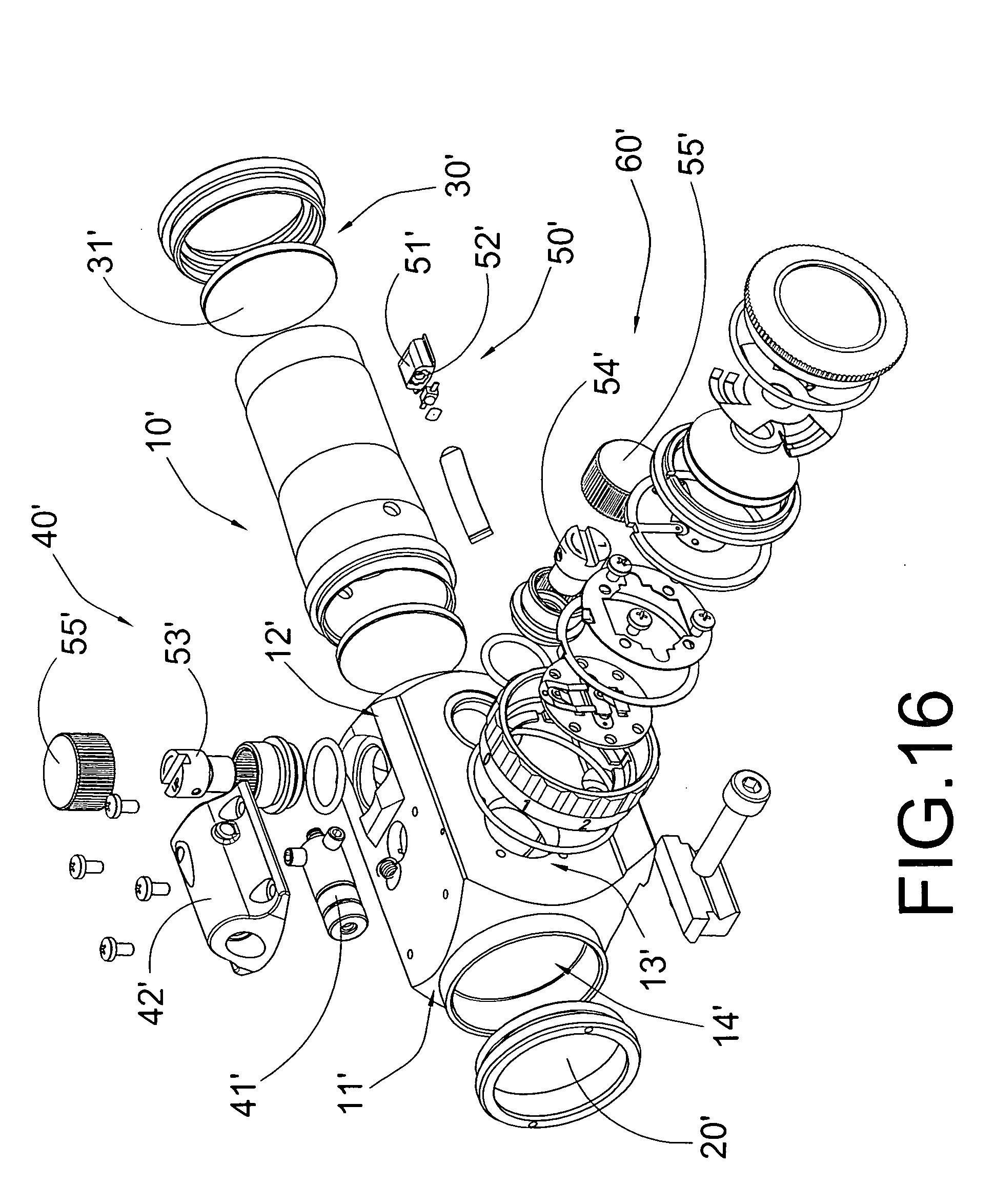
[0041] FIG. 16 is an exploded perspective view of the laser sighting device according to the above second preferred embodiment of the present invention.
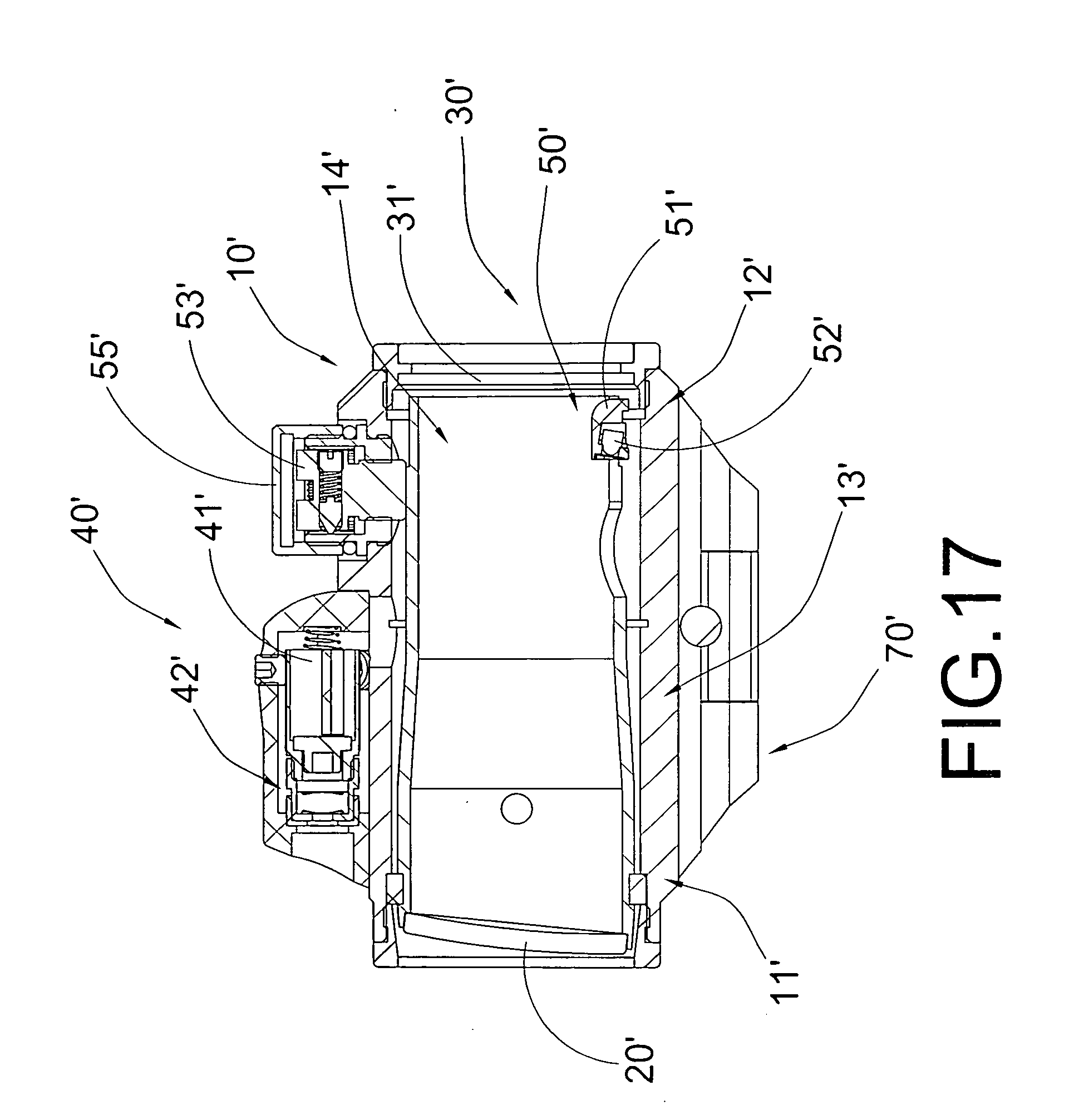
[0042] FIG. 17 is a sectional side view of the laser sighting device according to the above second preferred embodiment of the present invention.
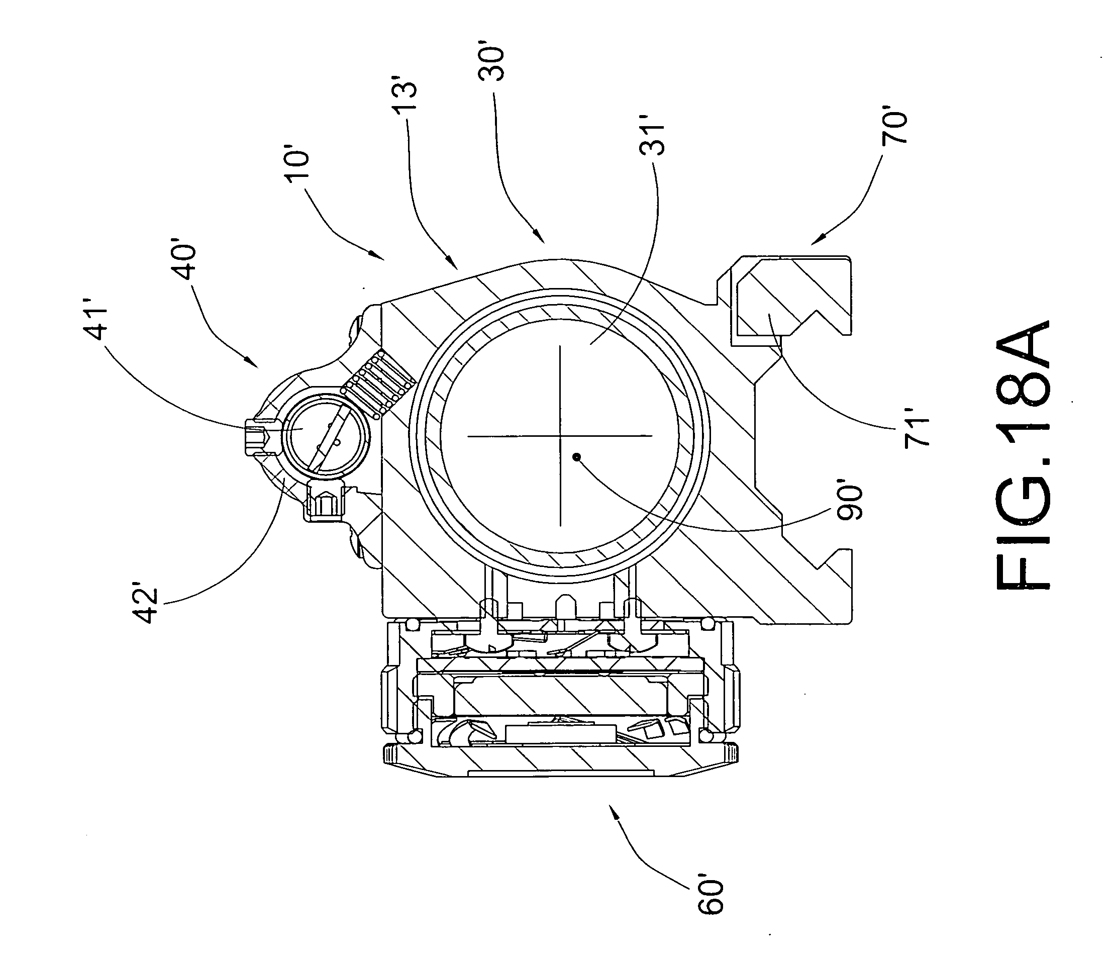
[0043] FIG. 18A and FIG. 18B are schematic diagrams of the laser sighting device according to the above second preferred embodiment of the present invention.
DETAILED DESCRIPTION OF THE PREFERRED EMBODIMENT
[0044] The description above and below and the drawings of the present document focus on one or more currently preferred embodiments of the present invention and also describe some exemplary optional features and/or alternative embodiments. The description and drawings are for the purpose of illustration and not limitation. Those of ordinary skill in the art would recognize variations, modifications, and alternatives. Such variations, modifications, and alternatives are also within the scope of the present invention. Section titles are terse and are for convenience only.
[0045] FIG. 1 is a top, left side perspective view of a laser sighting device in accordance with an embodiment of the present invention. Generally, the device 110 comprises a laser sighting assembly and an ocular sighting assembly, wherein the laser sighting assembly and the ocular sighting assembly serve as a single unit, the laser sighting assembly a non-removable component of the device.
[0046] In an embodiment of the invention, the ocular sighting assembly of the device may be a telescope. The telescope component of the device, may include an eyepiece portion 130 and an objective lens portion 140. The eyepiece portion 130 may comprise of ocular lens assemblies as known in the art and a reticle 76 coupled with a light-emitting diode (LED) 74, as shown in the cross-sectional view of FIG. 12. In an embodiment of the invention, the reticle 76 of the eyepiece portion 130 may be illuminated using LED 74. The objective lens portion 140 of an exemplary embodiment of the invention may comprise of a lens cap 1, objective lenses 9, 11, and other parts of an objective lens portion of a telescope as known in the art.
[0047] In an embodiment of the invention, a controller controls the illumination of the reticle. The controller may be, for example, a rheostat knob 58 terminating with a rubber coated cap 69. In one embodiment, the rheostat knob 58 is marked with a series of numbers 200, numbers "0" through "5" located next to the rubber coated cap 69 as shown in FIG. 10. The numbers represent different settings for the illumination of the reticle. The "0" setting provides no illumination to the reticle. The "1", "2", "3", "4" and "5" settings represent different levels of illumination or the reticle. For example, the "1" setting provides the lowest level of brightness to the reticle whereas the "5" setting provides the brightest.
[0048] FIG. 5 and FIG. 12 show the top view and top cross-sectional view of the laser sighting assembly attached to the telescope component according to embodiments of the invention. The laser sighting assembly may be positioned such that the laser diode module 53 emits a beam substantially along the same optical axis of the telescope, as shown in FIG. 7.
[0049] In an embodiment of the invention, the controller that controls the illumination of the reticle 76 also controls the illumination of the laser 53. In one embodiment, for example, a rheostat knob 58 controls both the reticle 76 illumination and the laser 53 illumination. In another embodiment, the rheostat knob 58 may control the on/off function of the laser, allowing the laser to be turned off while the reticle illumination is turned on, or alternatively, allowing the laser to be turned on while the reticle illumination is turned off. Additionally, the rheostat knob 58, may also control the simultaneous illumination of both the laser and the reticle. In one embodiment of the invention, the rheostat knob 58 provides setting "L" for laser illumination only and setting "B" to illuminate both the laser and the reticle. The rheostat knob 58 may, for example, be located on the left side of laser housing 54 on the left side of the scope as shown in FIG. 5 and FIG. 12.
[0050] In an embodiment of the invention, a single energy source provides the power to illuminate both the laser and the reticle. In another embodiment, the controller controls the illumination of the laser and the reticle, and houses the energy source for the illumination. In one embodiment as illustrated in FIG. 13, for example, the rheostat knob 58, may house a battery 64 for illuminating both the laser 53 and the reticle 76. In this embodiment of the invention, a battery 64 coupled with an electronic circuit assembly comprising electrode printed circuit boards (PCBs) 59, switch PCB 63, and surface mounted technology (SMT) components 115, or other electronic circuitry known in the art, allow power to be provided to the laser 53 and the reticle 76 from a single source. As shown, connection to the LED 120 and connection to the laser 125 is provided. Batteries housed in the rheostat knob may be removable.
[0051] FIG. 2 illustrates the laser sighting assembly with a mounting unit 111. In an embodiment of the invention, the mounting unit 111 is attached to the laser sighting device 110 and provides the means to mount the device onto a firearm. The mounting unit 111 may comprise of a release lever 42 that allows the shooter to mount and lock, or unlock and release the device from a firearm.
[0052] In an embodiment of the invention, the laser sighting device 110 is mounted onto a firearm by loosening the locking nut 51 while the release lever 42 is in the closed position pointing towards the eyepiece 130, as shown in FIG. 3 and the bottom view of FIG. 4. The locking nut 51 may be loosened by turning the nut counterclockwise. To mount the device, turn the release lever 42 in the open position by pointing the release lever 42 towards the objective lens. The set screw 49 may be loosened to fit the mounting unit 111 to the rail of a firearm. The laser sighting device 110 may be seated on top of the firearm's rail with the objective lens portion 140 pointing towards the muzzle of the firearm. When the preferred position of the laser sighting device is attained, the release lever 42 is positioned towards the eyepiece portion 130 in the closed position as shown in FIG. 3 and FIG. 6. To release the laser sighting device 110 from the firearm, open the quick release lever 42 and pivot the device 110 in the direction of the locking nut 51.
[0053] In an embodiment of the invention, once the laser sighting device 110 is properly mounted, an image of a target can be viewed and obtained through the ocular lens 80. The focus control 73 can be used and adjusted to obtain a clear image of a target through the eyepiece 130.
[0054] In an embodiment of the invention, the telescope component of the laser sighting device 110 may be zeroed using the windage adjuster screw 18 encompassed by the rubber turret cap 17 and elevation controller 29 as illustrated in FIGS. 7 and 8. In one embodiment, elevation is controlled with the Bullet Drop Compensator 29 (BDC) located on top of the turret housing 131 as shown in the cross sectional view of FIG. 11. In one embodiment, twisting the elevation control 29 counter-clockwise moves the reticle 76 crosshairs up, and twisting the elevation control 29 clockwise moves the reticle 76 crosshairs down. In one embodiment of the invention, for example, the BDC 29 is marked with numbers "1", "2", "3", "4" and "5" as illustrated in FIG. 9. Each number may represent increments of one hundred yards. In one embodiment, the shooting distance of the firearm may be adjusted by setting the BDC 29 to the number corresponding to the distances of one hundred to five hundred yards, in one hundred yard increments.
[0055] In another embodiment of the invention, the windage controller 18 is located on the right side of the laser sighting device as shown in FIG. 2 and FIG. 5. In one embodiment, the windage controller 18, as illustrated in FIG. 8 is an open target-style turret allowing ease of access at anytime. In one embodiment, twisting the windage controller 18 counter-clockwise will move the reticle 76 crosshairs to the right, and twisting the windage controller 18 clockwise will move the crosshairs to the left.
[0056] In another embodiment of the invention, a bore sighting device can be used to zero the laser sighting device.
[0057] In an embodiment of the invention, the laser 53 emitted from the laser sighting assembly may also be adjusted for windage and elevation with separate controllers. In one embodiment, the laser elevation controller 141 controls the elevation of the laser, as shown in FIG. 5. For example, twisting the laser elevation controller 141 counter-clockwise moves the laser up, and twisting the laser elevation control 141 clockwise moves the laser down. Additionally, twisting the laser windage controller 142 counter-clockwise moves the laser to the left, and twisting the laser windage controller 142 clockwise moves the laser to the right, as shown in FIG. 4 and FIG. 12.
[0058] As illustrated in FIG. 14, a detailed exploded view of the device 110 is described in which individual components of the exploded sections are discussed, according to an embodiment of the present invention. As mentioned, the device may comprise a telescope structure having an objective lens portion 140 and an eyepiece portion 130. As shown, the objective lens portion 140 is exploded to show the lens cap 1, protection glass 2, glass frame 3, and pin 4 for connecting the glass frame to the lens cap, and allowing the lens cap 1 to pivot open upwards. There is further an objective lens frame 7 having a locking ring for the lens frame 5 and a locking ring for the lens 6, a ring seal 8 and objective lenses 9 and 11 having an internal ring for separating lens 10. A ring seal 12 further engages with the objective lens 11 and housed within body 14 having plate spring 13. This objective lens portion 140 is housed within a rubber 15 coating structure, further connected to the turret housing 131.
[0059] On the right side of the turret housing 131 in FIG. 14, is integrated the adjustment controls for the telescope sight which includes the horizontal/windage controller 18 for the reticle crosshairs. As shown, a turret cap 16 terminates at the right with a rubber turret cap 17. The windage adjuster screw 18 is connected with the base 24 through ring seal 19, locking screw 20, anti-tightening screw 21, positioning spring 22 and stop pin 23. On the vertical of the turret housing 131, is integrated the elevation (up/down) adjustment of the telescope sight of the device, comprising a bullet drop compensator 29 encompassed within a rubber turret cap 27 with turret cap 26, terminating with rubber turret cap 25. Housed within the bullet drop compensator 29 is elevation adjuster screw 33, scale place 32, adjustment handle 31, stop pin 30, spring 28, locking ring 34, adjuster nut 35 and base 36 with positioning pin 37 and spring 38.
[0060] At the bottom of the device 110 is the mounting unit 111 comprising connection block 39 attached to plate 43 and mount boby 46 with screws 40, 41, pin 44, spring 45 and screws 47, 48, further connected to quick release lever 42, and adjuster plate 50 having set screw 49 and locking nut 51. Loosening set screw 49 and locking nut 51 allows for adjustment in attaching the device to a rail of a firearm.
[0061] FIG. 14 further shows the detailed exploded view of the integrated laser sighting assembly of the device. The assembly comprises laser housing 54 encompassing laser diode module 53 and adjuster plate spring 52, having locking screw 55 for the laser elevation controller 141, and locking screw 56 for the windage controller 142, seal 57 against Rheostat knob 58, adjacent to encompassing ring of rubber 60 adjacent to rubber cap 69. Within the Rheostat knob 58 are the electronic components including electrode PCB 59, positioning spring plate 61, screw 62, switch PCB 63, battery 64, anode gasket 65, washer 66, battery cover spring 67 with battery cover 68. The laser housing 54 is attached to the turret housing 131 as a single unit, with screws 70 fastened through laser housing 54. Laser windage controller 142 as shown in FIG. 12, further adjusts laser windage whereas elevation may be controlled by the separate laser elevation controller 141 as shown in FIG. 5
[0062] As further illustrated in FIG. 14, the exploded section of the eyepiece portion 130 and internal magnification tube with lens tube components are described. The eyepiece portion 130 extending from the rear of the turret housing 131 comprises a magnification ring 71, screw 72, rubber magnification ring 73 housing blue light-emitting diodes 74, reticle 76, stop screw 75, eyepiece tube 77 housed within rubber tube 78 further encompassing locking ring for ocular lens 79, ocular lenses 80, 82 separated by internal ring for separating lens 81, ring seals 83, 84, ocular lens frame 85, rubber ring 86 adjacent to glass frame 87 with protection glass 88. The glass frame 87 connected to lens cap 89 through a pin allowing for the lens cap 89 to pivot open upwards. Internal to the described eyepiece portion 130 is front joint 90, locking ring for lens 91, lens 92, separating ring 93 and washer 94, 107, magnification tube 95, lens frame 96 with sleeve 97 for engaging with screw 98. The structure further comprising lenses 99, 108, locking rings for lens 100, 102, lens frame 101, lens tube 103 adjacent to the rubber joint ring 104, locking ring 105 and lamp holder 106.
[0063] In one embodiment of the invention, the laser sighting assembly may sight a target by projecting a laser dot onto the target. In this manner, it may be unnecessary to use the telescope component of the laser sighting device to sight the target. For example, a shooter using a rifle mounted with the device could sight a target using the laser portion of the device without shouldering the rifle.
[0064] In another embodiment of the invention, the laser sighting device may be used as two sighting devices in one unit, telescope sighting and laser sighting.
[0065] In one embodiment, the telescope portion and the laser can be set to separate points of aim. In this embodiment, the laser sighting device can be set to two separate points of aim, each at separate or differing distances. For example, the telescope component can be adjusted to a point of aim that matches the bullet's point of impact at one hundred yards. Concurrently, the laser's point of aim can be adjusted to match the bullet point of impact at twenty-five yards. This provides two separate sources of sighting in one unit.
[0066] In another embodiment of the invention, the laser sighting assembly has adjustment controls that are independent of the telescope adjustment controls. In this embodiment, the laser and telescope can be set to separate points of aim. This allows two separate points of aim for two separate distances. For example, the telescope can be adjusted such that its point of aim matches the bullet point of impact at one hundred yards. At the same time, the laser sight point of aim can be adjusted to match the bullet point of impact at twenty-five yards. In this regard, there would be two sources of sighting combined in one unit.
[0067] Additionally, in another embodiment of the invention, because the laser physically projects a laser dot onto a target, laser and eye alignment is unnecessary. For example, it would be unnecessary for a shooter to shoulder the rifle in a traditional manner in order to obtain a desired shot placement. In an embodiment of the invention, the shooter can achieve the desired shot placement by holding the firearm in any manner as long as the laser dot is pointed on a target at a known distance.
[0068] In another embodiment, the laser and the telescope reticle points of aim could be adjusted to the same bullet point of impact. For example, both the laser and telescope reticle can be adjusted to match the bullet point of impact at one hundred yards. This positions the laser dot and the telescope reticle to aligned together with a target. The laser dot acts as additional shot placement verification as well as aiding shot placement in low light conditions.
[0069] Throughout the description and drawings, example embodiments are given with reference to specific configurations. It will be appreciated by those of ordinary skill in the art that the present invention can be embodied in other specific forms. Those of ordinary skill in the art would be able to practice such other embodiments without undue experimentation. The scope of the present invention, for the purpose of the present patent document, is not limited merely to the specific example embodiments or alternatives of the foregoing description.
[0070] Referring to FIG. 15 to FIG. 17, and FIG. 18A and FIG. 18B of the drawings, a laser sighting device according to a second preferred embodiment of the present invention is illustrated, in which the laser sighting device comprises a sighting scope 10', an objective lens 20', an ocular assembly 30', a laser locator 40', an illumination unit 50', and an operation switch 60'.
[0071] The sighting scope 10' defines a bell portion 11', a body portion 12' and an eyepiece portion 13', wherein the sighting scope 10' has a receiving cavity 14' formed along the bell portion 11', the body portion 12' and the eyepiece portion 13'.
[0072] The objective lens 20' is mounted at the bell portion 11' of the sighting scope 10' for focusing light at a focal point in the body portion 12' of the sighting scope 10'. The ocular assembly 30' comprises an ocular lens 31' provided at the eyepiece portion 13' of the sighting scope 10' for magnifying the light from the focal point.
[0073] The laser locator 40' is mounted at the body portion 12' of the sighting scope 10', and comprises a laser emitter 41' arranged to generate a laser beam toward a target. The illumination unit 50' is coupled with the ocular assembly 30' and is arranged to selectively provide illumination toward the ocular assembly 30'.
[0074] The operation switch 60' is provided on the sighting scope 10' to operate the laser sighting device at least between a laser mode and an illumination mode, wherein in the laser mode, the laser locator 40' is arranged to generate a laser beam toward a target from an exterior of the sighting scope 10', wherein in the illumination mode, the illumination unit is arranged to generate illumination toward the ocular assembly 30' from within the sighting scope 10' so that a user is able to observe an illumination pointer through the ocular lens 30' irrespective of whether the laser locator 40' is activated.
[0075] According to the second preferred embodiment, the sighting scope 10' is substantially circular in cross sectional shape in which a diameter of the bell portion 11', the body portion 12' and the eyepiece portion 13' are substantially the same.
[0076] The objective lens 20' is mounted in the bell portion 11' of the sighting scope 10' and is arranged to transmit and focus light from an exterior of the sighting scope 10' to the ocular assembly 30'. Note that it is the first optical element which modifies light coming from an exterior of the sighting scope 10'. Note that the laser sighting device of the present invention is designed to have a compact size so that the present invention can be fitted onto firearms or guns of smaller sizes.
[0077] The ocular lens 31' of the ocular assembly 30' is provided at the eyepiece portion 13' of the sighting scope 10' for magnifying the image captured by the objective lens 20'. As such, the shooter is able to telescopically observe the target at a distance and perform shooting from a position which is far away from where the target is positioned. The ocular assembly 30' preferably comprises a plurality of ocular lens 31' spacedly mounted in the eyepiece portion 13' for optimally magnifying the image captured by the objective lens 20'.
[0078] The laser locator 40' further comprises an emitter housing 42' mounted on top of the body portion 12' of the sighting scope 10', wherein the laser emitter 41' is received in the emitter housing 42' for selectively generating a laser beam in front of the laser sighting device. Thus, the emitter housing 42' serves to protect the laser emitter 41' and mount it on top of the sighting scope 10'
[0079] On the other hand, the illumination unit 50' comprises an illumination housing 51' mounted at a bottom portion of the body portion 12' of the sighting scope 10', and a LED 52' mounted in the illumination housing 51', wherein the LED is arranged to generate illumination toward the objective lens 20' for illustrating an illumination dot 80' on the ocular lens 31' so as to assist the user to locate the target when he or she is seeing through the ocular lens 31'.
[0080] The illumination unit 50' further comprises an elevation adjustment knob 53' operatively provided on a top surface of the body portion 12' of the sighting scope 10' and is connected with the LED 52' for controlling an elevation of the illumination dot 80' as seen through the ocular lens 30'. The elevation adjustment knob 53' can be rotated to adjust the elevation of the illumination dot 80' so that the user can be able to observe that the firearm or the gun is aiming correctly at the target.
[0081] Moreover, the illumination unit 50' further comprises an windage adjustment knob 54' operatively provided on a side surface of the body portion 12' of the sighting scope 10' and is connected with the LED 52' for controlling an windage movement (i.e. left and right displacement) of the illumination dot 80' as seen through the ocular lens 30'. Thus, the elevation adjustment knob 53' can be rotated to adjust the windage of the illumination dot 80' so that the user can be able to observe that the firearm or the gun is aiming correctly at the target.
[0082] In order to protect the elevation adjustment knob 53' and the windage adjustment knob 54', the illumination unit 50' further comprises a plurality of protective caps 55' removably coupled to the elevation adjustment knob 53' and the windage adjustment knob 54' respectively for normally protecting the elevation adjustment knob 53' and the windage adjustment knob 54' from exposing to ambient environment, while allowing the user to remove the corresponding protective cap 55' for adjusting the elevation adjustment knob 53' and/or the windage adjustment knob 54'.
[0083] The operation switch 60' is provided on a side surface of the body portion 12' of the sighting scope 10' and is arranged to switch the laser sighting device to operate between the laser mode and the illumination mode. More specifically, the operation switch 60' comprises a rheostat knob rotatably mounted on the body portion 12' of the sighting scope 10' in such a manner that the rheostat knob is capable of rotating between eight positions.
[0084] At the first position, the rheostat knob is set to turn both the laser emitter 41' and the LED 52' off. At the second position, the rheostat knob is set to turn on the laser emitter 41' only (FIG. 18A). At the third position, the rheostat knob is set to turn on the LED 52' only with maximum brightness. At the fourth position through the seventh position, the rheostat knob is set to turn on the LED 52' only with differing brightness, the fourth position being the brightest among these four positions, while the seventh position being the darkest among these four positions. At the eighth position, both the laser emitter 41' and the LED 52' are turned on for assisting the user in aiming a predetermined target (FIG. 18B).
[0085] Note also that the laser dot 90' and the illumination dot 80' generated by the laser emitter 41' and the LED 52' have different colors so that they can readily be identified by the user.
[0086] It is worth mentioning that the illumination unit 50' further comprises a reflective coating 56' formed on an outer side of the objective lens 20', wherein the reflective coating 56' is arranged to allow light from passing from inside the sighting scope 10' to an exterior thereof. Thus, when the illumination unit 50' is turned on, the LED dot will only appear on the objective lens 20' as seen from the ocular assembly 30', and it cannot be seen from any other viewing angle, such as from outside the sighting scope 10'. This is not the same as for the laser dot 90', because it is originated from outside the sighting scope 10'. Thus, anyone, including the user, may observe the laser dot 90' when the laser beam hits on a target.
[0087] Furthermore, the laser sighting device further comprises a mounting arrangement 70' provided at a bottom portion of the body portion 12' of the sighting scope 10' for mounting onto a firearm. More specifically, the mounting arrangement 70' comprises a mounting rail 71' extended along a bottom portion of the body portion 12' of the sighting scope 10', wherein the mounting rail 71' is arranged to mount onto a predetermined firearm, such as a gun, for allowing the user to utilize the laser sighting device when aiming a predetermined target.
[0088] Furthermore, the laser sighting device further comprises a cap apparatus 100' which comprises a plurality of protection covers 101' and a plurality of cover links 102' extended between the protection covers 101', wherein the cap apparatus 100' is made of flexible materials and is shaped and size to allow the protection covers to mount on the front and the rear side of the sighting scope for normally protecting the ocular assembly 30' and the objective lens 20' respectively.
[0089] One skilled in the art will understand that the embodiment of the present invention as shown in the drawings and described above is exemplary only and not intended to be limiting.
[0090] It will thus be seen that the objects of the present invention have been fully and effectively accomplished. It embodiments have been shown and described for the purposes of illustrating the functional and structural principles of the present invention and is subject to change without departure from such principles. Therefore, this invention includes all modifications encompassed within the spirit and scope of the following claims.
* * * * *
D00000
D00001
D00002
D00003
D00004
D00005
D00006
D00007
D00008
D00009
D00010
D00011
D00012
D00013
D00014

XML
uspto.report is an independent third-party trademark research tool that is not affiliated, endorsed, or sponsored by the United States Patent and Trademark Office (USPTO) or any other governmental organization. The information provided by uspto.report is based on publicly available data at the time of writing and is intended for informational purposes only.
While we strive to provide accurate and up-to-date information, we do not guarantee the accuracy, completeness, reliability, or suitability of the information displayed on this site. The use of this site is at your own risk. Any reliance you place on such information is therefore strictly at your own risk.
All official trademark data, including owner information, should be verified by visiting the official USPTO website at www.uspto.gov. This site is not intended to replace professional legal advice and should not be used as a substitute for consulting with a legal professional who is knowledgeable about trademark law.