Continuous Mechanical Tuning Of Transformers Inserted In Rf-safe Transmission Lines For Interventional Mri
Krueger; Sascha
U.S. patent application number 13/141095 was filed with the patent office on 2011-12-29 for continuous mechanical tuning of transformers inserted in rf-safe transmission lines for interventional mri. This patent application is currently assigned to KONINKLIJKE PHILIPS ELECTRONICS N.V.. Invention is credited to Sascha Krueger.
| Application Number | 20110314662 13/141095 |
| Document ID | / |
| Family ID | 41648092 |
| Filed Date | 2011-12-29 |

| United States Patent Application | 20110314662 |
| Kind Code | A1 |
| Krueger; Sascha | December 29, 2011 |
CONTINUOUS MECHANICAL TUNING OF TRANSFORMERS INSERTED IN RF-SAFE TRANSMISSION LINES FOR INTERVENTIONAL MRI
Abstract
A transformer line (46) extends through a catheter or other interventional instrument (30) that is to be used in the examination region (14) of a magnetic resonance imaging apparatus (10). The transformer line includes pairs of transformer windings (28) which are tuned in order to adjust the operating frequency and the maximum attenuation frequencies. Eccentric cams or other tuning elements (50, 64) are disposed in the transformer windings. Rotating the eccentric cams mechanically changes the geometry of the transformer windings, changing their inductive properties, and thus the frequency to which each is tuned.
| Inventors: | Krueger; Sascha; (Hamburg, DE) |
| Assignee: | KONINKLIJKE PHILIPS ELECTRONICS
N.V. EINDHOVEN NL |
| Family ID: | 41648092 |
| Appl. No.: | 13/141095 |
| Filed: | November 23, 2009 |
| PCT Filed: | November 23, 2009 |
| PCT NO: | PCT/IB2009/055300 |
| 371 Date: | June 21, 2011 |
Related U.S. Patent Documents
| Application Number | Filing Date | Patent Number | ||
|---|---|---|---|---|
| 61141947 | Dec 31, 2008 | |||
| Current U.S. Class: | 29/605 ; 324/309; 336/15 |
| Current CPC Class: | Y10T 29/49071 20150115; G01R 33/287 20130101; G01R 33/288 20130101 |
| Class at Publication: | 29/605 ; 336/15; 324/309 |
| International Class: | H01F 7/06 20060101 H01F007/06; G01R 33/44 20060101 G01R033/44; G01R 33/48 20060101 G01R033/48; H01F 21/04 20060101 H01F021/04 |
Claims
1. A transformer line for use in any of a variety of catheters or other interventional instruments, the transformer line comprising: at least one pair of transformer windings which inductively couple transmission line segments disposed in the interventional instrument; and at least one tuning element disposed adjacent at least one of the transformer windings configured to adjust a geometry of the transformer windings.
2. The transformer line according to claim 1, wherein the tuning elements are movable and are configured to deform the transformer winding as the tuning element is moved mechanically relative to the transformer winding.
3. The transformer line according to claim 2, further including: an access port defined through the interventional instrument adapted to receive a turning tool inserted to move the tuning element, the access port being sealable to cover the deforming element.
4. The transformer line according to claim 2, further including: a shaft extending from the movable tuning element and extending to an exterior of the interventional instrument.
5. The transformer line according to claim 2, wherein the tuning element includes an eccentric element rotatably disposed in the transformer windings.
6. The transformer line according to claim 2, wherein: the transformer winding is made of or mounted with a resilient material which exerts a physical force on the transformer windings in a direction opposite to a direction of deformation by the tuning element.
7. The transformer line according to claim 1, wherein: the transmission line segments, transformer windings and the tuning elements are configured to be assembled and tuned to an operating frequency after manufacturing the interventional instrument.
8. The transformer line according to claim 1, wherein the tuning elements are configured to mechanically adjust a spacing between the transformer windings and/or to mechanically adjust a radius of the transformer windings.
9. A catheter comprising: a coil disposed adjacent a tip end; a transformer line according to claim 1, extending through the catheter from the coil to a point of connection with associated electronic equipment.
10. A magnetic resonance system comprising: a magnet which generates a static magnetic field in an examination region; a radiofrequency transmit coil configured to induce and manipulate magnetic resonance in a subject in the examination region; and/or acquire magnetic resonance data from the examination region; and the interventional instrument including a transformer line according to claim 1.
11. The magnetic resonance system according to claim 10, wherein the interventional instrument includes: an interventional instrument coil connected with the transformer line and wherein the transformer line is electrically connected with at least one of a radiofrequency transmitter and a radiofrequency receiver.
12. A method of using a transformer line which includes at least a pair of transformer windings which inductively couple transmission line segments, the method comprising: installing the transformer line in an interventional instrument such as a catheter; adjusting a geometry of the transformer windings in order to tune the transformer line.
13. The method according to claim 12, wherein adjusting the geometry of the transformer windings includes one of: rotating an eccentric element which mechanically deforms at least one of the transformer windings as it is rotated; or pushing or pulling elements which mechanically deforms at least one of the transformer windings as it is pulled or pushed.
14. The method according to claim 13, wherein the tuning element is disposed internally in the interventional instrument and an access port is defined through the interventional instrument, the method comprising: inserting a tool through the port and moving the tuning element to deform the transformer windings; removing the tuning tool; and, sealing the access port.
15. The method according to claim 12, further including: positioning a subject in a magnetic resonance imaging system; using the interventional instrument within the magnetic resonance imaging system; performing magnetic resonance imaging while the interventional instrument is located in the magnetic resonance imaging system.
Description
[0001] The present application relates to a magnetic resonance apparatus which is provided with an active interventional device intended for use during the examination of a patient or other object during MR imaging. It finds particular application in improving safety, particularly in transmission lines.
[0002] A MR imaging system is often used for the examination and treatment of patients. By such a system, the nuclear spins of the body tissue to be examined are aligned by a static main magnetic field B.sub.0 and are excited by transverse magnetic fields B.sub.1 oscillating in the radiofrequency band. The resulting relaxation signals are exposed to gradient magnetic fields to localize the resultant resonance. The relaxation signals are received in order to form in a known manner a single or multiple dimension image.
[0003] Two types of MR systems that are in common use include "open" MR systems (vertical system) and "bore-type" systems. In the former, the patient is introduced into an examination zone which is situated between two magnetic poles connected by a c-shaped unit. The patient is accessible during the examination or treatment from practically all sides. Thelatter comprises a cylindrical examination space (axial system) into which a patient is introduced.
[0004] An RF coil system provides the transmission of RF signals and the reception of resonance signals. In addition to the RF coil system which is permanently built into the imaging apparatus, use is also made of surface coils which can be flexibly arranged, for example, as a sleeve or pad around or in a specific region to be examined.
[0005] Furthermore, use is made of active interventional devices which are introduced into the patient, for example, in order to take a tissue sample or perform a surgical act while the patient is in the imager. The interventional device usually has at least one coil element at its distal tip for the purpose of localization in the image formed or for the purpose of imaging.
[0006] Transmission lines or paths are provided for connecting the distal tip and/or other components in interventional devices like catheters, needles, stents, imaging coils, guidewires, and the like with an active unit, notably a power supply, a receiving/transmission device, a control unit, or the like. The active interventional devices usually have to be guided through MR fields which in the case of an MR system includes the B.sub.1 field, generated in the form of RF pulses which are transmitted by the RF coil system. Such RF fields may induce common mode signals (currents) in the transmission line and in the surrounding body tissue. Such common mode signal can cause large electric fields. These currents create not only the risk of disturbances or destruction of the accessory device and/or the active unit, but notably they can give rise to substantial heating of the adjacent tissue resulting in potentially severe burns of inner organs or blood/tissue coagulation for the patient.
[0007] To address these issues, safe transformer lines (STLs) have been proposed. By dividing the transmission line into short segments, inductively coupling the segments using transformers, and properly tuning the inductance/capacitance, the transmission line can be tuned to be non-resonant and therefore non-conductive for the problematic common mode currents while being resonant and therefore highly conductive for differential mode currents making the actual MR signal. The transformers inductively transmit the transmission line signal while robustly attenuating induced RF currents in the transmission line without having to use parallel resonant circuits that choke the RF currents which can generate hazardous localized heating, are bulky, and expensive to manufacture.
[0008] In practice, the safe transformer lines are initially tuned in the laboratory to the desired operating frequency. The STL is then integrated into the interventional device. The tuning does not anticipate variable environmental conditions such as the effect of the catheter structure as well as the effect of body tissue, air, bones, blood, and other electronic components in the device which can affect signal quality. Also, the transmission line segments and the transformers of the transformer line may not be tuned as designed, e.g. due to tolerances of the components, which can further degrade applicability.
[0009] The present application provides a new and improved safe transformer line that can be tuned to a particular environment after full device assembly which overcomes the above-referenced problems and others.
[0010] In accordance with one aspect, a transformer line is provided for use in any of a variety of catheters or interventional instruments. At least one pair of transformer windings which inductively couple transmission line segments are disposed in the interventional instrument. At least one tuning element is disposed adjacent at least one of the transformer windings and is configured to adjust a geometry of the transformer windings.
[0011] In accordance with another aspect, a method is provided for using a transformer line which includes at least one pair of transformer windings which inductively couple transmission line segments. The transformer line is mounted in an interventional instrument, such as a catheter. At least one tuning element which is disposed in the interventional instrument adjacent at least one of the transmission windings is used to adjust a geometry of the transformer windings.
[0012] One advantage allows for adjustments to the interventional device post manufacture.
[0013] Another advantage is that the design allows for multiple parallel lines to be integrated into the interventional device.
[0014] A further advantage resides in improved imaging, visualization, and localization.
[0015] Still further advantages of the present invention will be appreciated by those of ordinary skill in the art upon reading and understand the following detailed description.
[0016] The invention may take form in various components and arrangements of components, and in various steps and arrangements of steps. The drawings are only for purposes of illustrating the preferred embodiments and are not to be construed as limiting the invention.
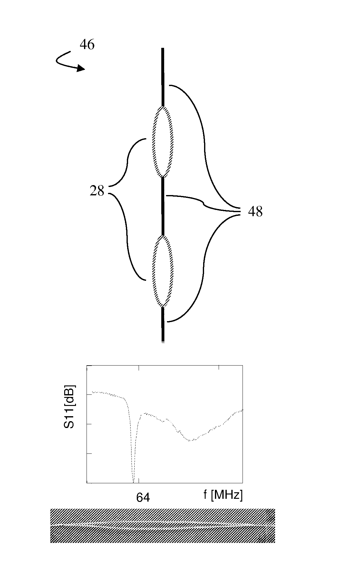
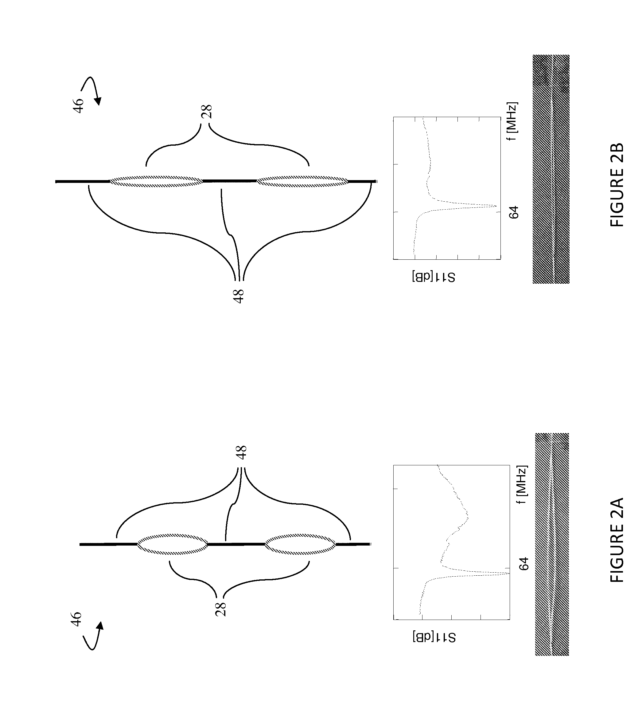
[0017] FIG. 1 is a diagrammatic side view in partial section of an MR apparatus along with an interventional instrument with continuously tunable transformer line;
[0018] FIGS. 2A and 2B are a demonstration of the frequency response of a continuously tunable transformer line;
[0019] FIG. 3 is a schematic view of a transformer line with deformable windings inside an interventional instrument such as a catheter or guidewire;
[0020] FIGS. 4A and 4B are schematic views of a transformer line with integrated turn-dilators to adjust the geometry of the transformer windings;
[0021] FIG. 5 is a schematic view of a transformer line with integrated turn-dilators to be operated though an access port for use with a turning tool;
[0022] FIG. 6 is a schematic view of a transformer line with integrated control wires to be operated though an access port for pushing and/or pulling the transforming windings.
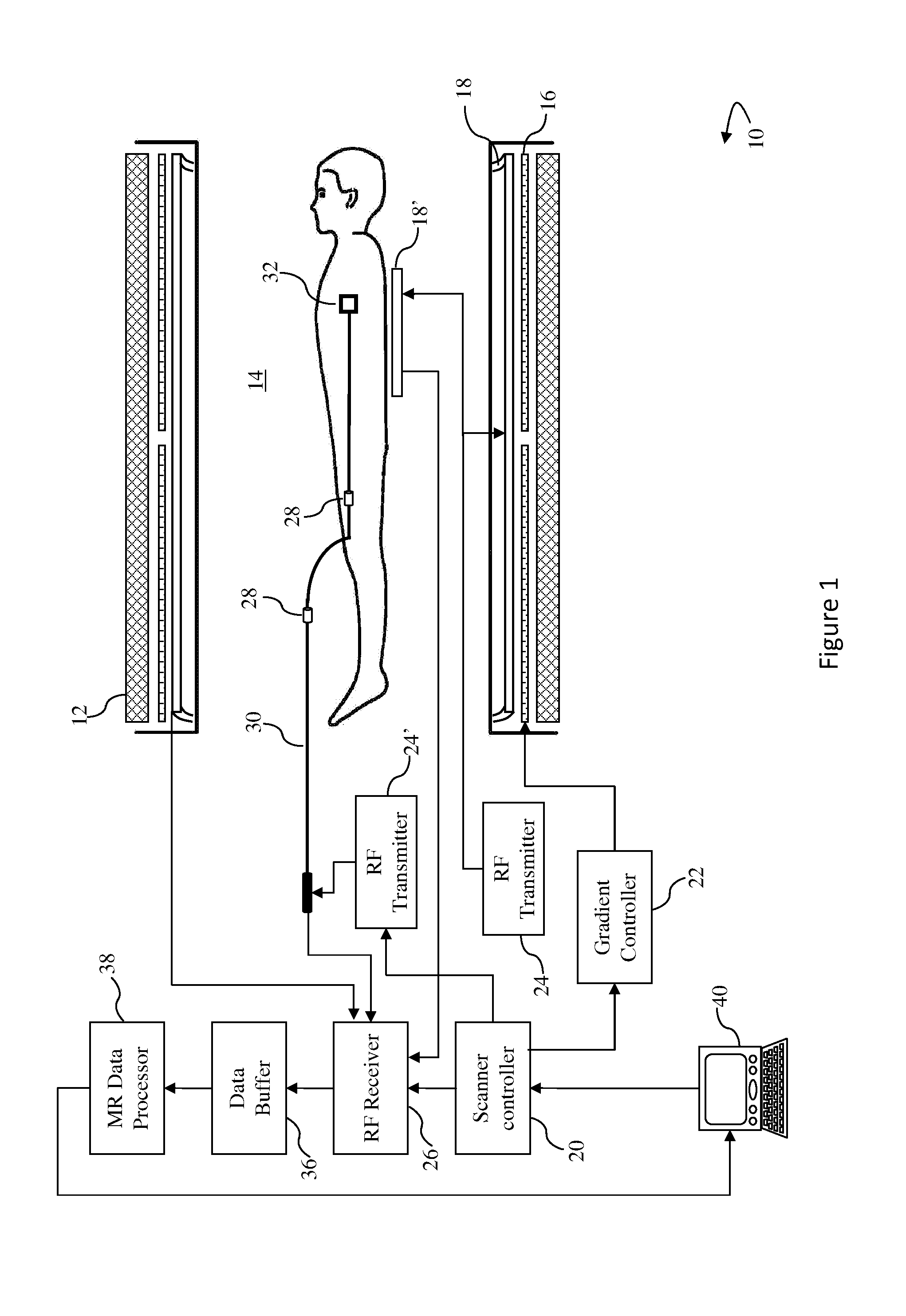
[0023] With reference to FIG. 1, a magnetic resonance imaging system 10 includes a main magnet 12 which generates a temporally uniform B.sub.0 field through an examination region 14. The main magnet can be an annular or bore-type magnet, a C-shaped open magnet, other designs of open magnets, or the like. Gradient magnetic field coils 16 disposed adjacent the main magnet serve to generate magnetic field gradients along selected axes relative to the B.sub.0 magnetic field. A radio frequency coil, such as a whole-body radio frequency coil 18 is disposed adjacent the examination region. Optionally, local or surface RF coils 18' are provided in addition to or instead of the whole-body RF coil 18.
[0024] A scan controller 20 controls a gradient controller 22 which causes the gradient coils to apply selected magnetic field gradient pulses across the imaging region, as may be appropriate to a selected magnetic resonance imaging or spectroscopy sequence. The scan controller 20 also controls an RF transmitter 24 which causes the whole-body or local RF coils to generate magnetic resonance excitation and manipulation B.sub.1 pulses. The scan controller also controls an RF receiver 26 which is connected to the whole-body or local RF coils to receive magnetic resonance signals therefrom.
[0025] An interventional instrument, such as a catheter 30, is held by the surgeon or clinician. Various other types of interventional instruments and catheters are contemplated. For example, the catheter may include a guide wire, a stent, an injector, a passage for introducing contrast agents or other fluids, etc. The catheter or other interventional instrument, in the illustrated embodiment, has a coil 32 disposed at a tip end thereof. Optionally, additional coils may be disposed along the length of the catheter. Optionally, other electrical equipment such as an amplifier, matching and tuning circuitry, or other circuitry, may be disposed in the tip of the catheter adjacent the coil 32. The catheter, particularly electrical conductors therein, are inductively coupled with the RF receiver 26 and/or an RF transmitter 24' via a safe transformer line with integrated deformable transformers 28 for tuning an assembled catheter or other interventional instrument. The RF transmitter 24' can be the same as the RF transmitter 24. Alternately, as illustrated in FIG. 1, the RF transmitters 24 and 24' can be different transmitters to facilitate the significantly different transmit power levels.
[0026] The interventional instrument coil 32 can be used in various ways. In one embodiment, RF localization signals are applied via the RF transmitter 24' to the coil 32. The localization signals are applied concurrently with gradients such that the frequency is indicative of location. In embodiments in which the coil 32 receives resonance signals induced in the adjacent tissue by the whole-body RF coil 18 or a local RF coil 18' on the exterior of the patient, the received resonance signals are sent to the RF receiver 26, which is preferably digital, to be processed analogous to other received magnetic resonance signals. Various other localization techniques are known. In some localization techniques, the coil 32 is caused to switch between resonant and non-resonant configurations. The magnetic field gradients 16 can be applied for spatially localizing the locator RF signal in a separate localization process or the localization of the coil can be processed concurrently with processing of the magnetic resonance signals. Various other electrical functions can also be performed in the interventional instrument. The STL is also able to transmit any type of signal that may be required for the respective functionality and can be also used to deliver power to active parts of the instrument. To this end, the respective signal may be frequency-modulated before transmission and demodulated afterwards in the receiver or for example, at the active element at the tip or elsewhere in the device. This is typically done for low frequency signals that are otherwise not transmitted efficiently via the inductive coupling-based STL.
[0027] The received data from the receiver 26 is temporarily stored in a data buffer 36 and processed by a magnetic resonance data processor 38. The magnetic resonance data processor can perform various functions as are known in the art, including image reconstruction, magnetic resonance spectroscopy, catheter or interventional instrument localization, and the like. Reconstructed magnetic resonance images, spectroscopy readouts, interventional instrument location information, and other processed MR data are displayed on a graphic user interface 40. The graphic user interface 40 also includes a user input device which a clinician can use for controlling the scan controller 20 to select scanning sequences and protocols, and the like.
[0028] With reference to FIGS. 2A and 2B, transformer line 46 includes segments of transmission line 48 that are inductively coupled to one another by the deformable transformers 28. The transformers are spaced at not more than quarter wavelength intervals (at the resonance frequency) in order to block the transfer of direct currents, off-resonance frequency currents, and common-mode resonance. More specifically, when the transformers 28 are in one state of deformation (or non-deformation), a signal is minimally attenuated just above 64 MHz, but attenuated at frequencies below this frequency. By changing the deformation as illustrated diagrammatically in FIG. 2B, the working frequency is shifted to just below 64 MHz. In this manner, the transformer deformation can be adjustably performed until the working frequency is moved to a selected frequency.
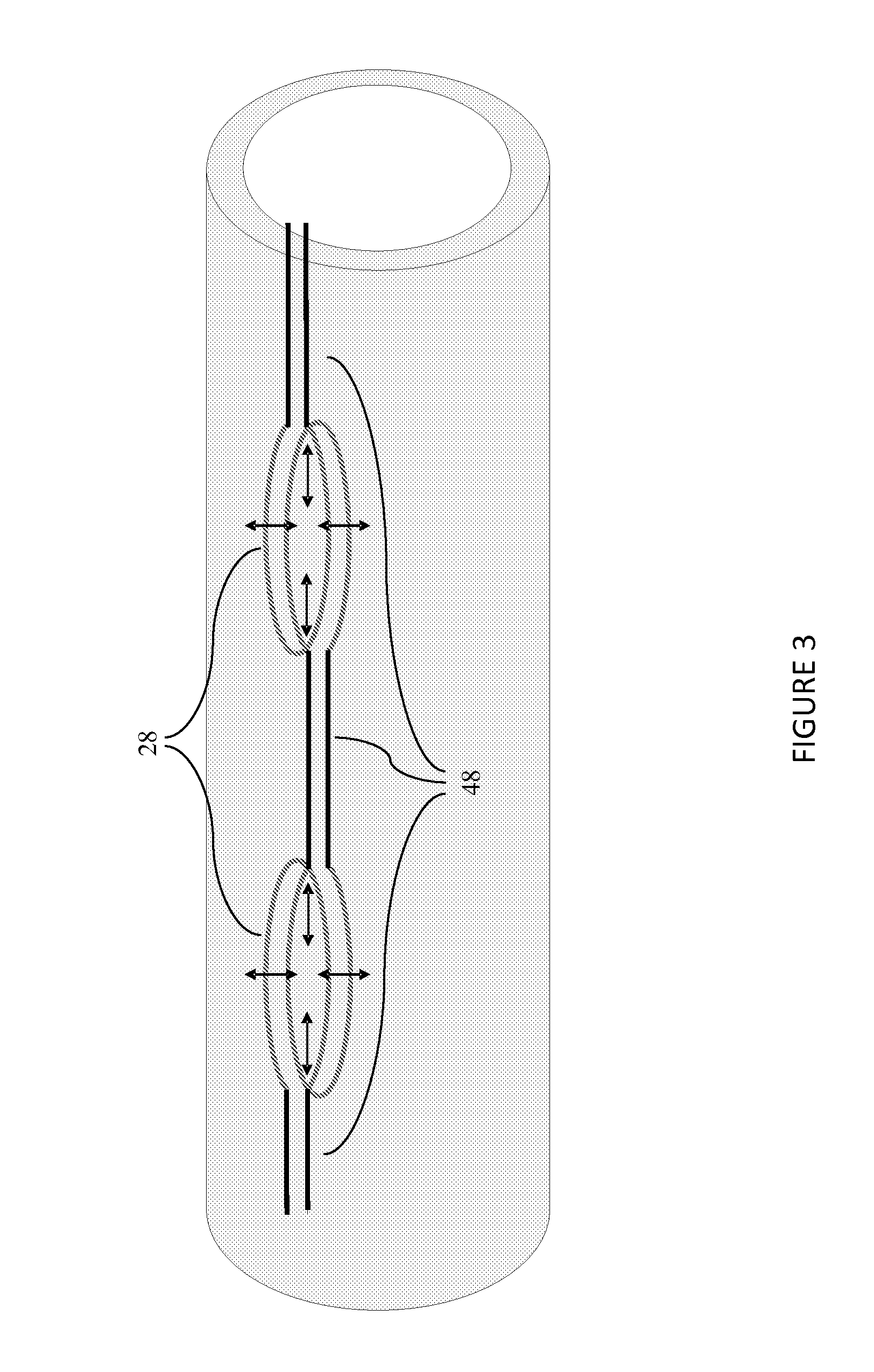
[0029] With reference to FIG. 3, the transformer coil pairs 28 connecting the transmission line segments 48 are configured such that they can be deformed in any of a plurality of directions. For example, the coils can be moved closer together or further apart. As another example, one of the coils may be elongated relative to the other. As another example, the coils can be transversely deformed. Various other mechanical deformations which modify the minimum impedance frequency of the transformer are contemplated.
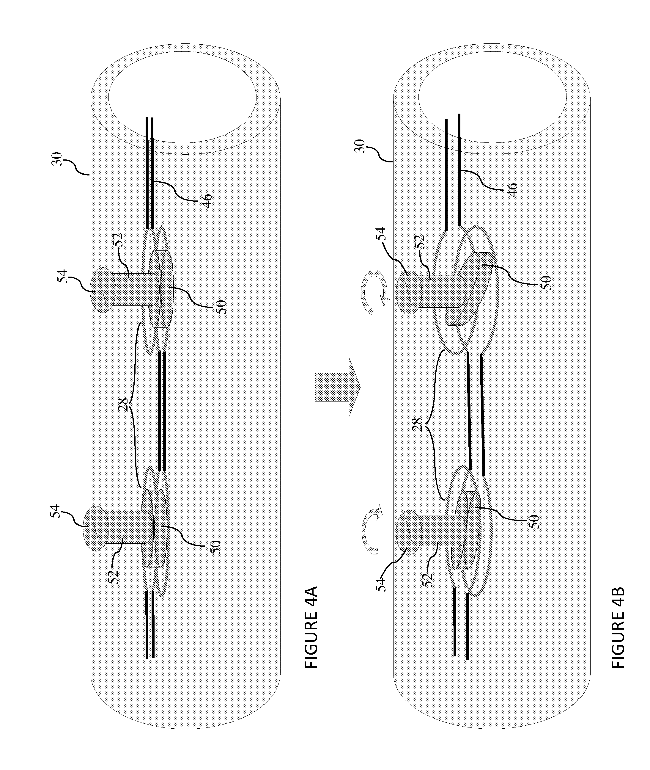
[0030] In the embodiment of FIG. 4A and FIG. 4B, the transformer line 46 is embedded in a catheter or other interventional device 30 which alters the frequency passing/attenuating characteristics of the transmission line due to other active components or material in the proximity of a transformer. Adjacent each transformer, a rotatable, eccentric cam 50 is embedded in the catheter 30 adjacent the transformers 28. The cams, in this embodiment, are connected with shafts 52 which, in turn, are connected with elements 54 for receiving a tool for rotating the cams 50. The cams 50 are positioned relative to the transformers 28, e.g., concentrically with the windings of the transformers 28, such that rotation of the cams 50 as illustrated in FIG. 4B, alters the shape and/or other physical characteristics of the transformers 28, and hence the frequencies which the coils pass and the frequencies which they attenuate. In this manner, each of the cams can be turned individually until its respective coil is tuned to the selected operating frequency. Typically, the transformers are tuned starting with the transformer closest to the distal tip, working backwards toward the end that is manipulated by the clinician and connected with the peripheral electronics.
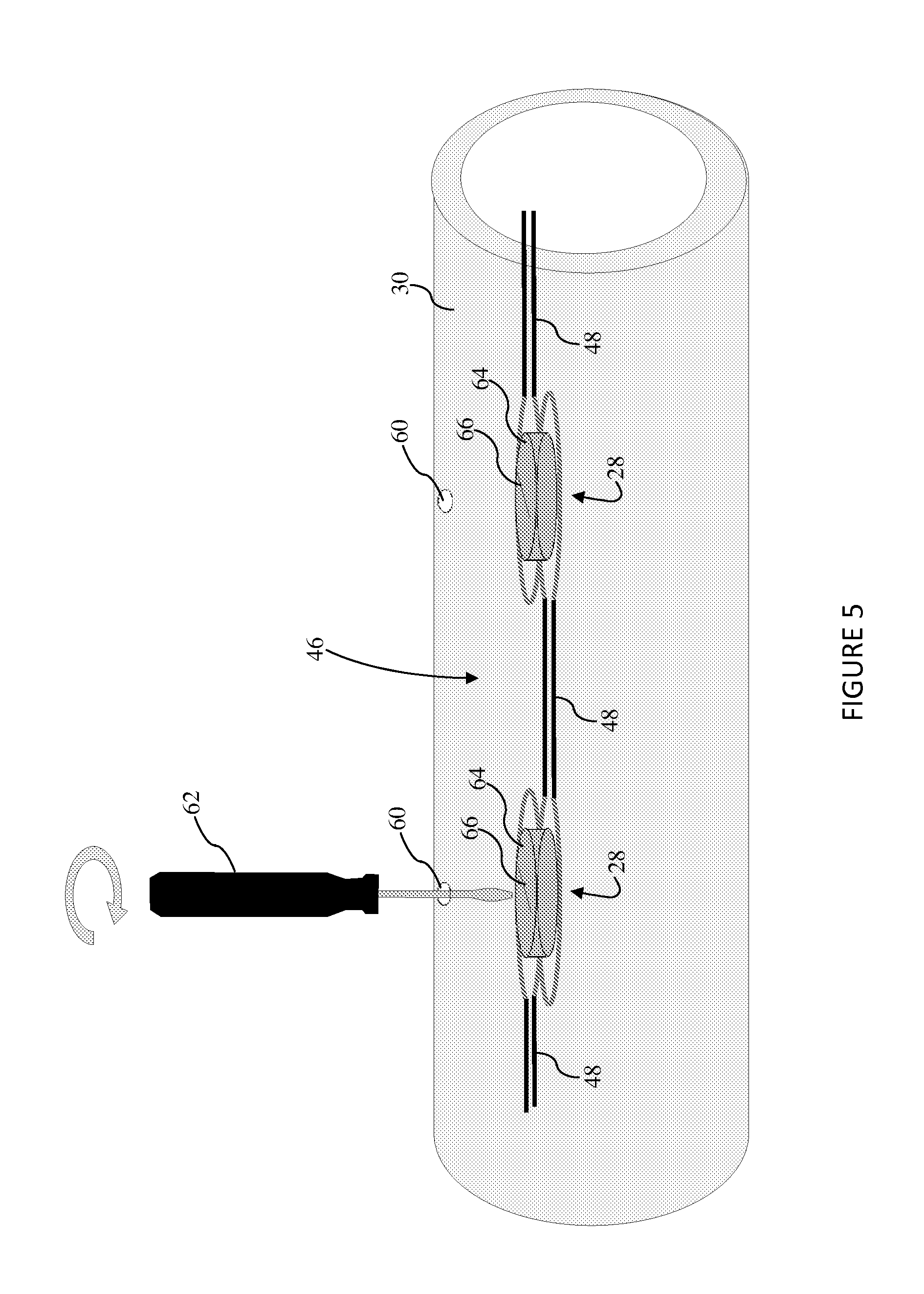
[0031] With reference to FIG. 5, other mechanical mechanisms for altering the physical characteristics of the transformers 28 are also contemplated. For example, the catheter or other interventional device can have apertures 60 defined through which a rotational tool 62, such as a screwdriver can extend in order to engage an eccentric cam 64 located adjacent one of the transformers 28. The eccentric cam includes a mechanical structure, a slot in the case of a screwdriver, for engaging the rotating tool 62. Optionally, once the cams have been rotated and the transformers have been appropriately tuned, the holes may be filled or sealed with a sealant which locks the cams in place and prevents further access. The sealant is preferably biocompatible, resistant to sterilants, and forms a fluid-tight seal.
[0032] With reference to FIG. 6, the transformer shape can be adjusted by control wires or rods 68 attached to the distal and/or proximal part of each transformer that may initially have, for example, a convex shape, so that pushing or pulling one end with respect to the other results in controllable deformation (stretching or warping) and hence tuning of the transformers.
[0033] Other mechanisms for changing the inductance and the frequency characteristics of the transformers are also contemplated. For example, rather than the eccentric cam 64, the port 60 can connect with a hollow cavity which is filled with a sealant under pressure which expands the coil windings. Once the desired frequency is attained, the sealant is cured such that the transformer is held in the selected degree of deformation.
[0034] In another optional embodiment, a bias is provided which biases the transformer windings inwards. In this manner, by rotating the cam in the opposite direction or reducing the pressure of the deforming polymer, the transformer can be tuned in the opposite sense.
[0035] In another embodiment, a hollow core of the transformer is filled with a material, such as ferrous or nickel nanoparticles, to change the inductance of the transformer.
[0036] The invention has been described with reference to the preferred embodiments. Modifications and alterations may occur to others upon reading and understanding the preceding detailed description. It is intended that the invention be constructed as including all such modifications and alterations insofar as they come within the scope of the appended claims or the equivalents thereof.
* * * * *
D00000
D00001
D00002
D00003
D00004
D00005
D00006
XML
uspto.report is an independent third-party trademark research tool that is not affiliated, endorsed, or sponsored by the United States Patent and Trademark Office (USPTO) or any other governmental organization. The information provided by uspto.report is based on publicly available data at the time of writing and is intended for informational purposes only.
While we strive to provide accurate and up-to-date information, we do not guarantee the accuracy, completeness, reliability, or suitability of the information displayed on this site. The use of this site is at your own risk. Any reliance you place on such information is therefore strictly at your own risk.
All official trademark data, including owner information, should be verified by visiting the official USPTO website at www.uspto.gov. This site is not intended to replace professional legal advice and should not be used as a substitute for consulting with a legal professional who is knowledgeable about trademark law.