Fastener Extension And Method Thereof
ANDERSON; LAWRENCE E.
U.S. patent application number 12/825312 was filed with the patent office on 2011-12-29 for fastener extension and method thereof. This patent application is currently assigned to LAWRENCE ANDERSON. Invention is credited to LAWRENCE E. ANDERSON.
| Application Number | 20110314593 12/825312 |
| Document ID | / |
| Family ID | 45351117 |
| Filed Date | 2011-12-29 |


View All Diagrams
| United States Patent Application | 20110314593 |
| Kind Code | A1 |
| ANDERSON; LAWRENCE E. | December 29, 2011 |
FASTENER EXTENSION AND METHOD THEREOF
Abstract
A method and device adapted to engage the fasteners of a garment to obviate closure of the fasteners of the garment comprising a body; at least one button hole engaging portion mounted on the body; at least one button engaging portion mounted on the body; whereby when the device is inserted in the garment, the at least one button hole engaging portion engages the button hole of the garment and the at least one button engaging portion engages the button of the garment. Alternatively, the method and device can be modified to be used with a hook and slot garment fasteners as described herein.
| Inventors: | ANDERSON; LAWRENCE E.; (ARLINGTON, VA) |
| Assignee: | ANDERSON; LAWRENCE ARLINGTON VA |
| Family ID: | 45351117 |
| Appl. No.: | 12/825312 |
| Filed: | June 28, 2010 |
| Current U.S. Class: | 2/338 |
| Current CPC Class: | A41B 1/16 20130101; A41F 9/025 20130101 |
| Class at Publication: | 2/338 |
| International Class: | A41F 9/00 20060101 A41F009/00 |
Claims
1. A device adapted to engage the fasteners of a garment to obviate closure of the fasteners of the garment comprising: a body; at least one button hole engaging portion mounted on the body; at least one button engaging portion mounted on the body; whereby when the device is inserted in the garment, the at least one button hole engaging portion engages the button hole of the garment and the at least one button engaging portion engages the button of the garment.
2. The device of claim 1 wherein the length of the body is adjustable.
3. The device of claim 1 wherein the at least one button engaging portion comprises a plurality of button engaging portions.
4. The device of claim 1 wherein the at least one button hole engaging portion comprises a plurality of button hole engaging portions.
5. The device of claim 1 wherein the body comprises a belt adapted to encircle the waist line the garment wearer.
6. The device of claim 1 wherein the device is adapted to be placed near the neck of the garment wearer and the at least one button hole engaging portion is adapted to engage the top button hole of a shirt and the at least one button engaging portion is adapted to engage the top button of a shirt.
7. The device of claim 1 wherein the device is adapted to be placed near the waist of the garment wearer and the at least one button hole engaging portion is adapted to engage the top button hole of the garment and the at least one button engaging portion is adapted to engage the top button of the garment.
8. The device of claim 7 wherein the garment is a pair of pants adapted to support a belt and the device is adapted to be placed above the zipper and behind the belt of a garment wearer.
9. A device adapted to engage the fasteners of a garment comprising: a body; at least one loop engaging portion mounted on the body; at least one clip engaging portion mounted on the body; whereby when the device is inserted in the garment, the at least one clip engaging portion engages the clip of the garment and the at least one loop engaging portion engages the loop of the garment whereby the circumference of the garment is extended at the location of the device.
10. The device of claim 9 wherein the length of the body is adjustable.
11. The device of claim 9 wherein the at least one clip engaging portion comprises a plurality of clip engaging portions.
12. The device of claim 9 wherein the at least loop engaging portion comprises a plurality of loop engaging portions.
13. The device of claim 9 wherein the body comprises a belt adapted to encircle the waist line the garment wearer.
14. The device of claim 9 wherein the device is adapted to be placed near the waist of the garment wearer and the at least one clip engaging portion is adapted to engage the clip of the garment and the at least one loop engaging portion is adapted to engage the loop of the garment.
15. The device of claim 14 wherein the garment is a pair of pants adapted to support a belt and the device is adapted to be placed above the zipper and behind the belt of a garment wearer.
16. A method for increasing the circumference of the garment by engaging the fasteners of a garment comprising: attaching a device between the fasteners of the garment, the device having a first portion for engaging a first fastener on the garment and a second portion for engaging the mating fastener on the garment, such that the circumference of the garment is increased upon closure of the circumference using the device.
17. The method of claim 16 wherein the fasteners are a button and a button hole, the device having first and second ends, the first end having at least one button engaging fastener and the second end having at least one button hole engaging fastener such that when the fasteners on the garment are engaged with the fasteners on the device, the circumference of the garment is extended by the approximate distance between the engaged button hole engaging fastener and the engaged button engaging fastener.
18. The method of claim 16 wherein the fasteners are a loop and a clip, the device having first and second ends, the first end having at least one clip engaging fastener and the second end having at least one loop engaging fastener such that when the fasteners on the garment are engaged with the fasteners on the device, the circumference of the garment is extended by the approximate distance between the engaged loop engaging fastener and the engaged clip engaging fastener.
Description
FIELD OF THE INVENTION
[0001] The present invention relates to the fastening of garments and the like.
BACKGROUND OF THE INVENTION
[0002] As people eat more, their bodies expand resulting in tight fitting clothes. Clothes are often made such as to surround certain portions of the body, such as the neck and waist, more closely than other portions. By increasing the circumference of the garment or clothing at the neck or waist, the wearer is able to extend the use of the garment, or wear the article of clothing in more comfort.
[0003] Clothing is intended to fit the public in general. Clothing sizes for many articles of clothing sold generally at stores are commonly use a single sizing, such as small, medium or large, to classify the clothing. Yet someone may have a larger neck or waist than the general population creating a dilemma when trying to find clothes that fit properly and that are comfortable. Shirts may vary in neck size, but this is frequently at a higher cost to the individual.
SUMMARY OF THE PRESENT INVENTION
[0004] A preferred embodiment comprises a first portion which engages a button, and a second portion which engages a button hole, and a body therebetween. The assembly or device may be integral or a combination of pieces and may be used on a garment, which may be for example, a shirt, blouse, pants, slacks, shirt, or the like.
[0005] A preferred embodiment of the present invention may comprise a metal, plastic, rubber and or a combination thereof base with a protrusion at or near a first end which is capable of engaging a button hole and at least one aperture at a second end which is adapted to engage a button. The protrusion may be a button or tab which is insertable into a button hole. The entire assembly may be one piece or may comprise multiple components or the same or a variety of materials, such as metal, plastic or rubber. The materials may be clear, translucent, white, black, khaki, blue, yellow and/or the color of the garment(s) for which the assembly is intended.
[0006] Optionally, the central portion or body may be elastic or capable of expanding to accommodate movement of the wearer or user. In the case of usage at the neckline, the distance between the button center and left end of the button hole may be from one half inch to an inch and a half (11/2) in order to lessen the tension of the shirt around the neck of the user while at the same time to permit a tie to cover the area and provide stable support for the tie.
[0007] Optionally, the central portion may be adjustable in length or the elasticity may be adjustable to permit expansion of the body to accommodate stretching or expansion of the body portion surrounded or encompassed by the garment and/or to make the garment more comfortable for the wearer/user.
[0008] Additional aspects and/or advantages of the invention will be set forth in part in the description which follows and, in part, will be obvious from the description, or may be learned by practice of the invention.
BRIEF DESCRIPTION OF THE DRAWINGS
[0009] These and/or other aspects and advantages of the invention will become apparent and more readily appreciated from the following description of the embodiments, taken in conjunction with the accompanying drawings of which: The drawings of this invention are illustrative and diagrammatic in nature in order to present the principles of the invention. They are being provided as examples without limiting the invention to the specific configuration or dimensions shown.
[0010] FIG. 1 is a schematic illustration showing a plan view of a preferred embodiment assembly the present invention.
[0011] FIG. 2A is a schematic view of the preferred embodiment of FIG. 1.
[0012] FIG. 2B is a schematic top view of the preferred embodiment of FIG. 1.
[0013] FIG. 2C is a schematic illustration of the FLAP 8 used in the preferred embodiment of FIG. 1.
[0014] FIG. 3 is a schematic view of another preferred embodiment of having a plurality of buttons 3.
[0015] FIG. 4 is a schematic view of another preferred embodiment of having an adjustable Velcro.RTM. attachment 7.
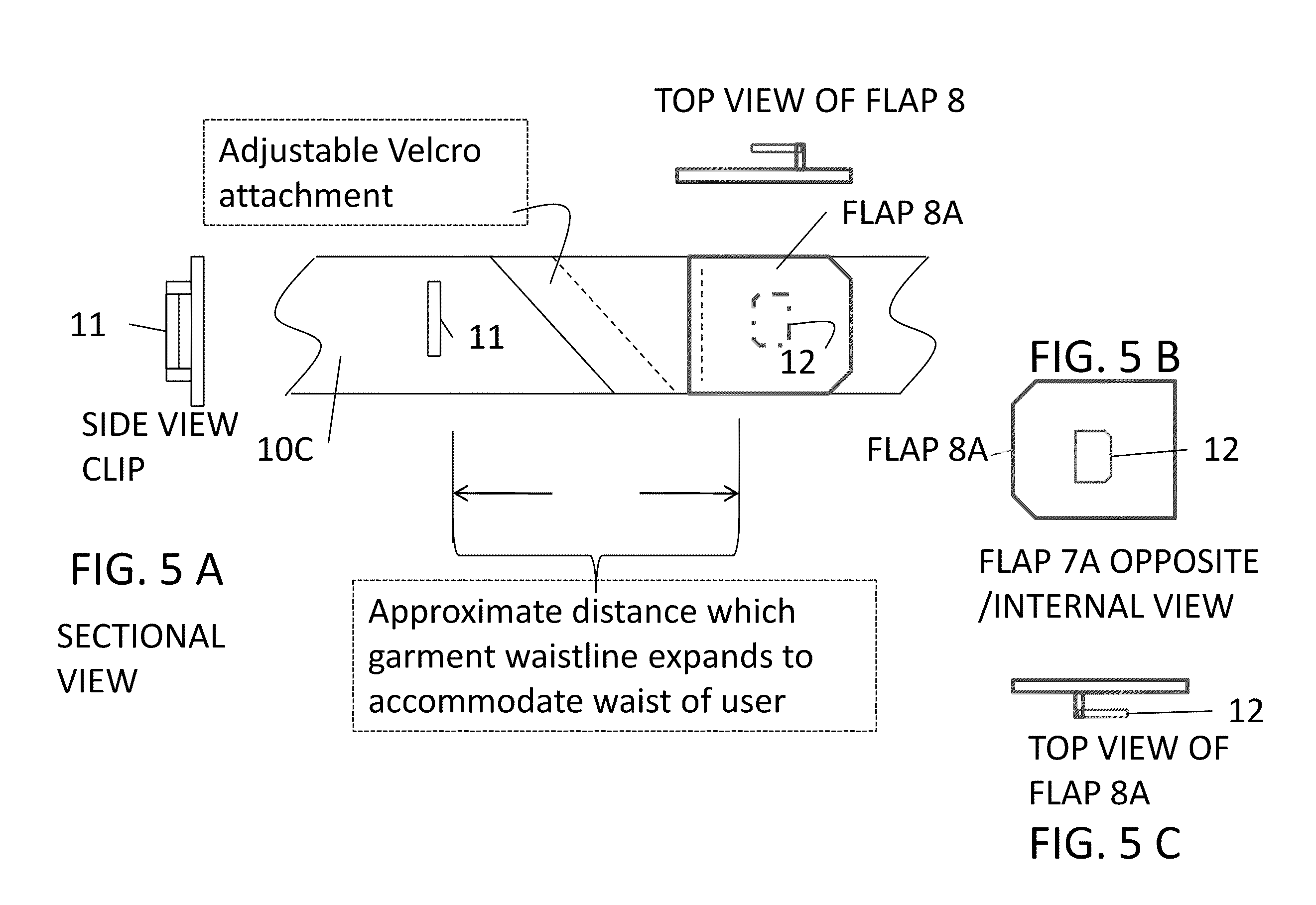
[0016] FIG. 5A is a schematic view of another preferred embodiment of having an adjustable Velcro.RTM. attachment 7 wherein the clasping mechanism is a hook or clip 12 and loop or slot 11.
[0017] FIG. 5B is a schematic view taken from the opposite side of flap 8A.
[0018] FIG. 5C is a schematic top view of flap 8A of FIG. 5B.
[0019] FIG. 6A is a schematic illustration of another preferred embodiment having an adjustable length wherein the clasping mechanism is a hook or clip 12 and slot or loop 11. The adjustable length may be either Velcro.RTM. (top) or elastic (middle).
[0020] FIG. 6B is a schematic view of a section taken from the opposite side of clip or hook.
[0021] FIG. 6C is a top view of clip or hook 12 of FIG. 6B
[0022] FIG. 7A is a schematic illustration of another preferred embodiment having a plurality of loops or slots 11. Optionally, the body 10E may be elastic.
[0023] FIG. 7B is a schematic illustration of the embodiment of FIG. 7A illustrating a side view of metallic loop or slot 11.
[0024] FIG. 7C is a schematic top view of the embodiment of FIG. 7A.
[0025] FIG. 8 is a schematic illustration of another preferred embodiment utilizing Velcro.RTM. to make the length of body 10F adjustable.
[0026] FIG. 9 is a schematic top view of a preferred embodiment comprising a button hole flap 8.
[0027] FIG. 10 is a schematic top view of a preferred embodiment comprising a button hole flap 8 and overlapping bodies 10H and 10K. Bodies 10H and 10K may be removably secured together by Velcro.RTM., by protrusions 22 and valleys 21 (shown in FIGS. 30A, 30B, 31A, 31B) or by protrusions 22A and valleys or undulations 33 as shown in FIG. 32A-D.
[0028] FIG. 11 is a schematic top view of a preferred embodiment comprising a button hole flap 8 and overlapping bodies 10H and 10K, illustrating Velcro hooks 7 therebetween.
[0029] FIG. 12 is a schematic top view of a preferred embodiment comprising a button hole flap 8 and overlapping bodies 10H and 10K, illustrating Velcro hooks 7 therebetween further showing a front view of a garment, which may be for example, a shirt, blouse, pants, slacks, shirt, or the like.
[0030] FIG. 13 is a schematic top view of a preferred embodiment comprising a button hole flap 8 and overlapping bodies 10L and 10M, illustrating Velcro hooks 7 therebetween and a plurality of buttons 3; further showing a front view of a garment, which may be for example, a shirt, blouse, pants, slacks, shirt, or the like.
[0031] FIG. 14 is a schematic front view of a preferred embodiment comprising a button hole 2 and button 3 on a body 10N; further showing a front view of a garment, which may be for example, a shirt, blouse, pants, slacks, shirt, or the like.
[0032] FIG. 15A is a schematic front view of a preferred embodiment comprising a button hole 2 on body 10M1 and a button 3 on a body 10L1 having hooks 7 for providing adjustment; further showing a front view of a garment, which may be for example, a shirt, blouse, pants, slacks, shirt, or the like.
[0033] FIG. 16A is a schematic front view of a preferred embodiment comprising a button hole 2 and a button 3 on a body 10Q having elastic 6 for providing adjustment; further showing a front view of a garment, which may be for example, a shirt, blouse, pants, slacks, shirt, or the like. Optionally, the entire body 10Q may be elastic.
[0034] FIG. 17A is a schematic front view of a preferred embodiment comprising a plurality of button holes 2 and a button 3 on a body 10Q having elastic 6 for providing adjustment; further showing a front view of a garment, which may be for example, a shirt, blouse, pants, slacks, shirt, or the like. Optionally, the entire body 10Q may be elastic.
[0035] FIG. 18A is a schematic front view of a preferred embodiment comprising a plurality of button holes 2 and a plurality of buttons 3 on a body 10R having elastic 6 for providing adjustment; further showing a front view of a garment, which may be for example, a shirt, blouse, pants, slacks, shirt, or the like.
[0036] FIG. 18B is a schematic top view of the preferred embodiment of FIG. 18A.
[0037] FIG. 19A is a front view of a preferred embodiment comprising a plurality of button holes 2 and a plurality of buttons 3 on a body 10S having elastic 6 for providing adjustment; further showing a front view of a garment, which may be for example, a shirt, blouse, pants, slacks, shirt, or the like.
[0038] FIG. 19B is a schematic top view of the preferred embodiment of FIG. 19A.
[0039] FIG. 20A is a schematic front view of a preferred embodiment comprising a plurality of button holes 2 and a plurality of buttons 3 on a body 10T; further showing a front view of a garment, which may be for example, a shirt, blouse, pants, slacks, shirt, or the like.
[0040] FIG. 20B is a schematic top view of the preferred embodiment of FIG. 20A.
[0041] FIG. 21 is a schematic illustration showing a plan view of a preferred embodiment assembly the present invention comprising a body 10U; which provides for a lowering of the garment on the wearer.
[0042] FIG. 22 is a schematic illustration showing a plan view of a preferred embodiment assembly the present invention comprising a body 10V; which provides for a lowering of the garment on the wearer.
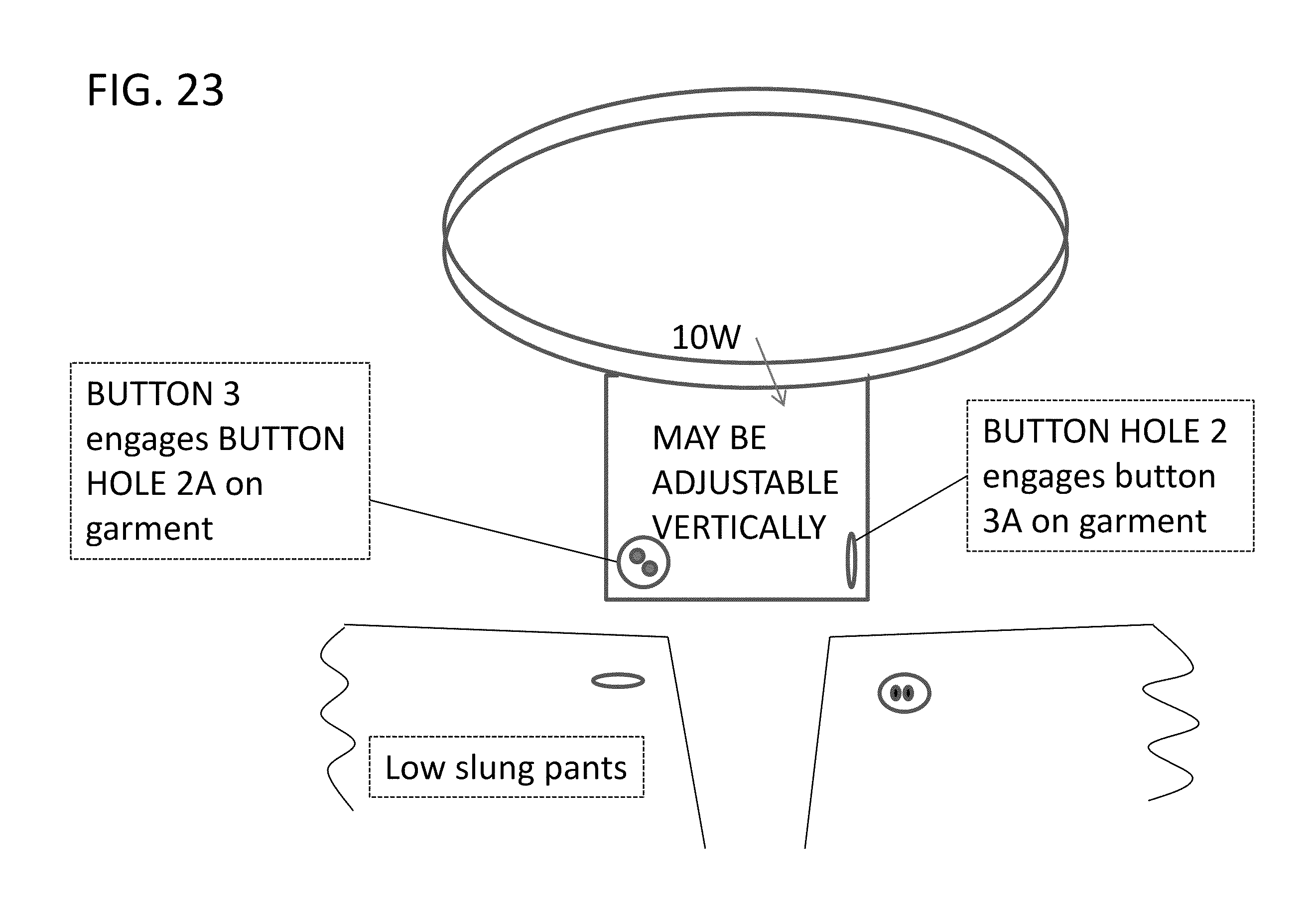
[0043] FIG. 23 is a schematic illustration showing a plan view of a preferred embodiment assembly the present invention comprising a body 10W optionally comprising a plurality of buttons 3 and/or button holes 2; which provides for a lowering of the garment on the wearer.
[0044] FIG. 24A is a schematic illustration showing a plan view of a preferred embodiment assembly the present invention comprising a body 10W optionally comprising a plurality of buttons 3 and/or button holes 2; which provides for a lowering of the garment on the wearer. Optionally, the body portion may be adjustable using Velcro.RTM. or the body assembly using protrusions 22A and channel with valleys or undulations shown in FIG. 24B and FIG. 32A.
[0045] FIG. 25A is a schematic illustration showing a front view of a preferred embodiment assembly the present invention comprising a body 10T optionally comprising a protrusion 3B and/or button holes 2. Optionally, the body portion may be integral.
[0046] FIG. 25B is a schematic top view of the preferred embodiment of FIG. 25A.
[0047] FIG. 26A is a schematic illustration showing a front view of a preferred embodiment assembly the present invention comprising a body 10T1 optionally comprising a protrusion 3B and/or button holes 2 and a screw adjuster 13.
[0048] FIG. 26B is a schematic top view of the preferred embodiment of FIG. 26A.
[0049] FIG. 27A is a schematic illustration showing a front view of a preferred embodiment assembly the present invention comprising a body 10TS optionally comprising a protrusion 3B and/or button holes 2; also showing a garment.
[0050] FIG. 27B is a schematic top view of the preferred embodiment of FIG. 27A.
[0051] FIG. 28A is a schematic illustration showing a front view of a preferred embodiment assembly the present invention comprising body portions 10X and 10W forming an adjustable assembly by which protrusion(s) 22 (optionally more than one) is adapted to fit in valleys 21, further comprising a button 3.
[0052] FIG. 28B is a schematic side view of the preferred embodiment of FIG. 28A.
[0053] FIG. 29A is a schematic illustration showing a front view of a preferred embodiment assembly the present invention comprising body portions 10X and 10W forming an adjustable assembly by which protrusion(s) 22 (optionally more than one) is adapted to fit in valleys 21; further comprising a protrusion 3B instead of a button 3.
[0054] FIG. 29B is a schematic side view of the preferred embodiment of FIG. 29A.
[0055] FIG. 30A is a schematic illustration showing a front view of a preferred embodiment assembly the present invention comprising body portions 10X and 10WX assembled together forming an adjustable assembly by which protrusion(s) 22 (optionally more than one) is adapted to fit in valleys 21; optionally comprising a protrusion 3B instead of a button 3.
[0056] FIG. 30B is a schematic side view of the preferred embodiment of FIG. 30A.
[0057] FIG. 31A is a schematic illustration showing a front view of a preferred embodiment assembly the present invention comprising body portions 10XP and 10WP assembled together forming an adjustable assembly by which protrusion(s) 22A (optionally more than one) is adapted to fit into valleys undulations 33; optionally comprising a protrusion 3B instead of a button 3.
[0058] FIG. 31B is a schematic side view of the preferred embodiment of FIG. 31.
[0059] FIG. 31C is a schematic end view of the preferred embodiment of FIG. 31.
[0060] FIG. 31D is a schematic end view of an optional open embodiment resembling the preferred embodiment of FIG. 31.
DETAILED DESCRIPTION OF PREFERRED EMBODIMENTS
[0061] The invention now will be described more fully hereinafter with reference to the accompanying drawings, in which embodiments of the invention are shown. This invention may, however, be embodied in many different forms and should not be construed as limited to the embodiments set forth herein. Rather, these embodiments are provided so that this disclosure will be thorough and complete, and will fully convey the scope of the invention to those skilled in the art. Like reference numerals refer to like elements throughout the description of the figures.
[0062] It will be understood that when an element is referred to as being "on" another element, it can be directly on the other element or intervening elements may be present. In contrast, when an element is referred to as being "directly on" another element, there are no intervening elements present. It will be understood that when an element is referred to as being "connected" or "coupled" to another element, it can be directly connected or coupled to the other element or intervening elements may be present. In contrast, when an element is referred to as being "directly connected or coupled" to another element, there are no intervening elements present. Furthermore, "connected" or "coupled" as used herein may include wirelessly connected or coupled. As used herein, the term "and/or" includes any and all combinations of one or more of the associated listed items.
[0063] It will be understood that, although the terms first, second, etc. may be used herein to describe various elements, these elements should not be limited by these terms. These terms are only used to distinguish one element from another. For example, a first layer could be termed a second layer, and, similarly, a second layer could be termed a first layer without departing from the teachings of the disclosure.
[0064] The terminology used herein is for the purpose of describing particular embodiments only and is not intended to be limiting of the invention. As used herein, the singular forms "a", "an" and "the" are intended to include the plural forms as well, unless the context clearly indicates otherwise. It will be further understood that the terms "comprises" and/or "comprising," or "includes" and/or "including" when used in this specification, specify the presence of stated features, regions, integers, steps, operations, elements, and/or components, but do not preclude the presence or addition of one or more other features, regions, integers, steps, operations, elements, components, and/or groups thereof.
[0065] Furthermore, relative terms, such as "lower" or "bottom" and "upper" or "top," may be used herein to describe one element's relationship to other elements as illustrated in the Figures. It will be understood that relative terms are intended to encompass different orientations of the device in addition to the orientation depicted in the Figures. For example, if the device in one of the figures were turned over, elements described as being on the "lower" side of other elements would then be oriented on "upper" sides of the other elements. The exemplary term "lower", can therefore, encompass both an orientation of "lower" and "upper," depending of the particular orientation of the figure. Similarly, if the device in one of the figures is turned over, elements described as "below" or "beneath" other elements would then be oriented "above" the other elements. The exemplary terms "below" or "beneath" can, therefore, encompass both an orientation of above and below.
[0066] Unless otherwise defined, all terms (including technical and scientific terms) used herein have the same meaning as commonly understood by one of ordinary skill in the art to which this invention belongs. It will be further understood that terms, such as those defined in commonly used dictionaries, should be interpreted as having a meaning that is consistent with their meaning in the context of the relevant art and the present disclosure, and will not be interpreted in an idealized or overly formal sense unless expressly so defined herein.
[0067] Embodiments of the present invention are described herein with reference to cross section illustrations that are schematic illustrations of idealized embodiments of the present invention. As such, variations from the shapes of the illustrations as a result, for example, of manufacturing techniques and/or tolerances, are to be expected. Thus, embodiments of the present invention should not be construed as limited to the particular shapes of regions illustrated herein but are to include deviations in shapes that result, for example, from manufacturing. For example, a region illustrated or described as flat may, typically, have rough and/or nonlinear features. Moreover, sharp angles that are illustrated may be rounded. Thus, the regions illustrated in the figures are schematic in nature and their shapes are not intended to illustrate the precise shape of a region and are not intended to limit the scope of the present invention.
[0068] A preferred embodiment comprises an inner belt extender for use, for example with pants which are too tight due to an expanding waistline. There is a need to fasten the pants around the waist line while at the same time providing enough room to make the fit and feel comfortable. The button extender operates to hold the button hole at a comfortable length from the button while at the same time providing support from the waist and/or of the wearer.
[0069] FIG. 1 is a schematic illustration showing a plan view of a preferred embodiment assembly the present invention. The button extender of FIG. 1 comprises a belt-like accessory which encircles the waist for support, has an adjustable length button hole for the button on the garment (e.g. pants or slacks) and a button which enters the button on the garment. The belt-like accessory may have its own attachment fasteners (such as Velcro, clips, snaps or buttons and may be extendable or be made of an elastic material. The belt-like accessory wraps around the waist line and links to both the button and the button-hole on the garment while in essence bridging the distance there between in comfortable fashion.
[0070] The preferred embodiments of FIGS. 1-31 circumvents the need to pull the pants, shirt, slacks, shirt, etc., together tightly enough so that the garment may be buttoned. The usage of the preferred embodiments of FIGS. 1-31 is not limited to a given pair of pants or garment and may be made adjustable to accommodate a variety of apparel items. In essence, the preferred embodiments of FIGS. 1-31 conforms to the waist line or neck of the wearer and provides secure attachment of the garment item without an uncomfortable or confining fit, while at the same time retaining the garment (if pants) at or near the waist line of the user/wearer, and if a shirt, may be used in conjunction with an overlapping tie to present a neat appearance.
[0071] FIG. 2A is a schematic view of the preferred embodiment of FIG. 1. The button hole flap 8 is anchored on one side to the body 10B and is extended outward. The garment portion is intended to fit within the "V" between the flap 8 and body 10B. The body and flap may be of a variety of materials including plastic and cloth. The body 10 B may be expandable to accommodate movement of the wearer. The body 10B may hook together using Velcro.RTM. or fasteners such as snaps, buttons, clasps or hooks. FIG. 2B is a schematic top view of the preferred embodiment of FIG. 1. FIG. 2C is a schematic illustration of the Flap 8 used in the preferred embodiment of FIG. 1 showing the opposite side.
[0072] FIG. 3 is a schematic view of another preferred embodiment of having a plurality of buttons 3. The garment portion is intended to fit within the "V" between the flap 8 and body 10B. The body and flap may be of a variety of materials including plastic and cloth. The body 10B may be expandable to accommodate movement of the wearer. The body 10B may hook together using Velcro.RTM. or fasteners such as snaps, buttons, clasps or hooks. The approximate distance which the garment waistline is expanded is depicted in FIG. 3. This may be from a half an inch to 21/2 inches; but preferably, if a zipper is present, this will be approximately an inch. This will accommodate the wearer without putting undue force on the zipper.
[0073] FIG. 4 is a schematic view of another preferred embodiment of having an adjustable Velcro.RTM. attachment 7. Although show using diagonal lines; any configuration will suffice. The body and flap may be of a variety of materials including plastic and cloth. The body 10 B may be expandable to accommodate movement of the wearer. Instead of Velcro.RTM., fasteners such as snaps, buttons, clasps or hooks. The approximate distance which the garment waistline is expanded is depicted in FIG. 4. This may be from a half an inch to 21/2 inches; but preferably, if a zipper is present, this will be approximately an inch. This will accommodate the wearer without putting undue force on the zipper.
[0074] FIG. 5A is a schematic view of another preferred embodiment of having an adjustable Velcro.RTM. attachment 7 wherein the clasping mechanism is a hook or clip 12 and slot 11. The body portion 10C may be the same in material and nature as the body 10B. The body and flap may be of a variety of materials including plastic, elastic, and cloth. The body 10 C may be expandable to accommodate movement of the wearer. The body 10C may hook together using Velcro.RTM. or fasteners such as snaps, buttons, clasps or hooks. The approximate distance which the garment waistline is expanded is depicted in FIG. 5A. This may be from a half an inch to 21/2 inches; but preferably, if a zipper is present, this will be approximately an inch. This will accommodate the wearer without putting undue force on the zipper. FIG. 5A shows a side view of a slot or loop 11, which is commonly found on garments and has a variety of dimensions and is generally formed of a metallic material. FIG. 5B is a schematic view taken from the opposite side of flap 8A showing a hook or clip 12 which is commonly found on garments and has a variety of dimensions and is generally formed of a metallic material. FIG. 5C is a schematic top view of flap 8A of FIG. 5B.
[0075] FIG. 6A is a schematic illustration of another preferred embodiment having an adjustable length wherein the clasping mechanism is a hook or clip 12 and slot or loop 11; substantially the same as that of FIGS. 5A & B. The adjustable length may be either Velcro.RTM. (top) or elastic (middle). In addition, the entire body 10D may be elastic. The body 10D may be expandable to accommodate movement of the wearer.
[0076] FIG. 6B is a schematic view of a section taken from the opposite side showing hook or clip 12 which is commonly found on garments and has a variety of dimensions and is generally formed of a metallic material. FIG. 6C is a top view of hook or clip 12 of FIG. 6B
[0077] FIG. 7A is a schematic illustration of another preferred embodiment having a plurality of slots 11. Optionally, the body 10E may be elastic. The body 10E may be expandable to accommodate movement of the wearer. The body 10E may be made from a variety of materials including cloth, PVC, plastic, synthetic rubber, metal, aluminum, steel, etc. It may be integral or formed using individual components secured together. FIG. 7B is a schematic illustration of the embodiment of FIG. 7A illustrating a side view of slot or loop 11. FIG. 7C is a schematic top view of the embodiment of FIG. 7A.
[0078] FIG. 8 is a schematic illustration of another preferred embodiment utilizing Velcro.RTM. to make the length of body 10F adjustable. The body 10F may be similar to body 10B, the characteristics of which are hereby incorporated by reference, and may be expandable to accommodate movement of the wearer. The body 10B may hook together using Velcro.RTM. or fasteners such as snaps, buttons, clasps or hooks.
[0079] FIG. 9 is a schematic top view of a preferred embodiment comprising a button hole flap 8. Body 10G may be similar in all respects to bodies 10C, 10D and 10E, the characteristics of which are incorporated by reference. The body and flap may be of a variety of materials including plastic, metal, elastic, and cloth. The body 10 C may be expandable to accommodate movement of the wearer. Flap 8 may be made of the same cloth, plastic, metal, or the like, or of a material different from the body.
[0080] FIG. 10 is a schematic top view of a preferred embodiment comprising a button hole flap 8 and overlapping bodies 10H and 10K. Bodies 10H and 10K may be of materials similar in all respects to those of bodies 10D and 10E, the characteristics of which are incorporated by reference. Bodies 10H and 10K may be removably secured together by Velcro.RTM., by protrusions 22 and valleys 21 (shown in FIGS. 30A, 30B, 31A, 31B) or by protrusions 22A and valleys or undulations 33 as shown in FIG. 32A-D.
[0081] FIG. 11 is a schematic top view of a preferred embodiment comprising a button hole flap 8 and overlapping bodies 10H and 10K, illustrating Velcro hooks 7 therebetween. Bodies 10H and 10K may be of materials similar in all respects to those of bodies 10D and 10E, the characteristics of which are incorporated by reference. The bodies 10H, 10K and flap may be of a variety of materials including plastic, metal, elastic, and cloth.
[0082] FIG. 12 is a schematic top view of a preferred embodiment comprising a button hole flap 8 and overlapping bodies 10H and 10K, illustrating Velcro hooks 7 therebetween further showing a front view of a garment, which may be for example, a shirt, blouse, pants, slacks, shirt, or the like. Bodies 10H and 10K may be of materials similar in all respects to those of bodies 10D and 10E, the characteristics of which are incorporated by reference.
[0083] FIG. 13 is a schematic top view of a preferred embodiment comprising a button hole flap 8 and overlapping bodies 10L and 10M, illustrating Velcro hooks 7 therebetween and a plurality of buttons 3; further showing a front view of a garment, which may be for example, a shirt, blouse, pants, slacks, shirt, or the like.
[0084] FIG. 14 is a schematic front view of a preferred embodiment comprising a button hole 2 and button 3 on a body 10N; further showing a front view of a garment, which may be for example, a shirt, blouse, pants, slacks, shirt, or the like.
[0085] FIG. 15A is a schematic front view of a preferred embodiment comprising a button hole 2 on body 10M1 and a button 3 on a body 10L1 having hooks 7 for providing adjustment; further showing a front view of a garment, which may be for example, a shirt, blouse, pants, slacks, shirt, or the like. Bodies 10L1 and 10M1 may be of materials similar in all respects to those of bodies 10D,10E, 10H, and 10 K, the characteristics of which are incorporated by reference. The bodies 10L1 and 10M1 may be of a variety of materials including plastic, metal, elastic, and cloth.
[0086] FIG. 16A is a schematic front view of a preferred embodiment comprising a button hole 2 and a button 3 on a body 10Q optionally having elastic 6 for providing adjustment; further showing a front view of a garment, which may be for example, a shirt, blouse, pants, slacks, shirt, or the like. Optionally, the entire body 10Q may be elastic and/or the may be of a variety of materials including plastic, and cloth.
[0087] FIG. 17A is a schematic front view of a preferred embodiment comprising a plurality of button holes 2 and a button 3 on a body 10Q having elastic 6 for providing adjustment; further showing a front view of a garment, which may be for example, a shirt, blouse, pants, slacks, shirt, or the like. Optionally, the entire body 10Q may be elastic and/or the may be of a variety of materials including plastic, and cloth. FIG. 17A illustrates how the placement of the body 10Q is made relative to the garment. The body 10Q may vary in length from an inch to three or four inches, depending upon the application. In the case of usage at the neckline, the distance between the button center and left end of the button hole may be from one half inch to an inch and a half in order to lessen the tension of the shirt around the neck of the user while at the same time to permit a tie to cover the area and provide stable support for the tie.
[0088] FIG. 18A is a schematic front view of a preferred embodiment comprising a plurality of button holes 2 and a plurality of buttons 3 on a body 10R having elastic 6 for providing adjustment; further showing a front view of a garment, which may be for example, a shirt, blouse, pants, slacks, shirt, or the like. The bodies 10R may be of a variety of materials including plastic, metal, elastic, and cloth. Optionally elastic 6 may be provided. Buttons 3 and button holes 2 may be mounted in a straight line or in a variety of configurations.
[0089] FIG. 18B is a schematic top view of the preferred embodiment of FIG. 18A.
[0090] FIG. 19A is a front view of a preferred embodiment comprising a plurality of button holes 2 and a plurality of buttons 3 on a body 10S having elastic 6 for providing adjustment; further showing a front view of a garment, which may be for example, a shirt, blouse, pants, slacks, shirt, or the like. FIG. 19B is a schematic top view of the preferred embodiment of FIG. 19A.
[0091] FIG. 20A is a schematic front view of a preferred embodiment comprising a plurality of button holes 2 and a plurality of buttons 3 on a body 10T; further showing a front view of a garment, which may be for example, a shirt, blouse, pants, slacks, shirt, or the like. Buttons 3 and button holes 2 may be mounted in a straight line or in a variety of configurations. Body 10T may be made of the same or similar materials as bodies 10D,10E, 10H, and/or 10 K, the characteristics of which are incorporated by reference.
[0092] FIG. 20B is a schematic top view of the preferred embodiment of FIG. 20A. Body 10U may be made of the same or similar materials as bodies 10D,10E, 10H, and/or 10 K, the characteristics of which are incorporated by reference. The belt portion may be fabricated in a manner similar to 10B.
[0093] FIG. 21 is a schematic illustration showing a plan view of a preferred embodiment assembly the present invention comprising a body 10U; which provides for a lowering of the garment on the wearer. Body 10U may be made of the same or similar materials as bodies 10D,10E, 10H, and/or 10 K, the characteristics of which are incorporated by reference. The belt portion may be fabricated in a manner similar to 10B. In the embodiments shown in FIGS. 21-24, the assembly may be used to essentially lower the pants on the waist line while the belt portion of the preferred embodiment encircles the waistline.
[0094] FIG. 22 is a schematic illustration showing a plan view of a preferred embodiment assembly the present invention comprising a body 10V; which provides for a lowering of the garment on the wearer. Body 10V may be made of the same or similar materials as bodies 10D,10E, 10H, and/or 10 K, the characteristics of which are incorporated by reference. The belt portion may be fabricated in a manner similar to 10B.
[0095] FIG. 23 is a schematic illustration showing a plan view of a preferred embodiment assembly the present invention comprising a body 10W optionally comprising a plurality of buttons 3 and/or button holes 2; which provides for a lowering of the garment on the wearer. Body 10W may be made of the same or similar materials as bodies 10D,10E, 10H, and/or 10 K, the characteristics of which are incorporated by reference. The belt portion may be fabricated in a manner similar to 10B.
[0096] FIG. 24A is a schematic illustration showing a plan view of a preferred embodiment assembly the present invention comprising a body 10W optionally comprising a plurality of buttons 3 and/or button holes 2; which provides for a lowering of the garment on the wearer. Optionally, the body portion may be adjustable using Velcro.RTM. or the body assembly using protrusions 22A and channel with valleys or undulations shown in FIG. 24B and FIG. 32A. Body 10W may be made of the same or similar materials as bodies 10D,10E, 10H, and/or 10 K, the characteristics of which are incorporated by reference. The belt portion may be fabricated in a manner similar to 10B.
[0097] FIG. 25A is a schematic illustration showing a front view of a preferred embodiment assembly the present invention comprising a body 10T optionally comprising a protrusion 3B and/or button holes 2. Optionally, the body portion may be integral. Body 10T may be made of the same or similar materials as bodies 10D,10E, 10H, and/or 10 K, the characteristics of which are incorporated by reference. FIG. 25B is a schematic top view of the preferred embodiment of FIG. 25A. Preferably, in order to reduce fabrication costs, the entire embodiment may be formed of a single piece of rubber, plastic or metal. The piece made be molded in the case of plastic or rubber, it may be cut or stamped from a sheet or material. In the case of metal, the piece may be stamped from a sheet of metal such as tin or aluminum. In the case of metal, the button holes may be enlarged to accommodate the size of the button.
[0098] FIG. 26A is a schematic illustration showing a front view of a preferred embodiment assembly the present invention comprising a body 10T1 optionally comprising a protrusion 3B and/or button holes 2 and a screw adjuster 13. Body 10TI may be made of the same or similar materials as bodies 10D,10E, 10H, and/or 10 K, the characteristics of which are incorporated by reference. The screw portion may be similar in nature to the fastening means on a ball point pen. The belt portion may be fabricated in a manner similar to 10B.
[0099] FIG. 26B is a schematic top view of the preferred embodiment of FIG. 26A.
[0100] FIG. 27A is a schematic illustration showing a front view of a preferred embodiment assembly the present invention comprising a body 10TS optionally comprising a protrusion 3B and/or button holes 2; also showing a garment. Body 10TS may be made of the same or similar materials as bodies 10D,10E, 10H, and/or 10 K, the characteristics of which are incorporated by reference. The belt portion may be fabricated in a manner similar to 10B.
[0101] FIG. 27B is a schematic top view of the preferred embodiment of FIG. 27A.
[0102] FIG. 28A is a schematic illustration showing a front view of a preferred embodiment assembly the present invention comprising body portions 10X and 10W forming an adjustable assembly by which protrusion(s) 22 (optionally more than one) is adapted to fit in valleys 21, further comprising a button 3. The bodies 10X and 10W may be made of the same or similar materials as bodies 10D,10E, 10H, and/or 10 K, and/or combinations thereof, the characteristics of which are incorporated by reference. Preferably the bodies 10X and 10W are fabricated using synthetic rubber or PVC, and may be elastic and flexible. FIG. 28B is a schematic side view of the preferred embodiment of FIG. 28A. FIG. 29A is a schematic illustration showing a front view of a preferred embodiment assembly the present invention comprising body portions 10X and 10W forming an adjustable assembly by which protrusion(s) 22 (optionally more than one) is adapted to fit in valleys 21; further comprising a protrusion 3B instead of a button 3. The bodies of FIGS. 29A, 30A, and 31A may be fabricated of materials as those described in conjunction with the bodies shown in FIG. 28A, the characteristics of which are hereby incorporated by reference.
[0103] FIG. 29B is a schematic side view of the preferred embodiment of FIG. 29A. FIG. 30A is a schematic illustration showing a front view of a preferred embodiment assembly the present invention comprising body portions 10X and 10WX assembled together forming an adjustable assembly by which protrusion(s) 22 (optionally more than one) is adapted to fit in valleys 21; optionally comprising a protrusion 3B instead of a button 3. The bodies of FIGS. 29A, 30A, and 31A may be fabricated of materials as those described in conjunction with the bodies shown in FIG. 28A, the characteristics of which are hereby incorporated by reference. FIG. 30B is a schematic side view of the preferred embodiment of FIG. 30A.
[0104] FIG. 31A is a schematic illustration showing a front view of a preferred embodiment assembly the present invention comprising body portions 10XP and 10WP assembled together forming an adjustable assembly by which protrusion(s) 22A (optionally more than one) is adapted to fit into valleys undulations 33; optionally comprising a protrusion 3B instead of a button 3. The bodies of FIGS. 29A, 30A, and 31A may be fabricated of materials as those described in conjunction with the bodies shown in FIG. 28A, the characteristics of which are hereby incorporated by reference. FIG. 31B is a schematic side view of the preferred embodiment of FIG. 31. FIG. 31C is a schematic end view of the preferred embodiment of FIG. 31. FIG. 31D is a schematic end view of an optional open embodiment resembling the preferred embodiment of FIG. 31. In the alternative, the embodiment of 31A may combine the side protrusions 22A with protrusions across the body 10XP as shown in FIG. 31A or be around the circumference of the body 10XP and engage undulations on the inner surface of the channel 10WP shown in FIGS. 32C and 32D without departing from the spirit of the present invention.
[0105] As used in the following claims, the terminology clip means the metallic fastener found on pants (such as men's dress pants) resembling in appearance the element 12 shown in FIG. 5B and FIG. 5C and equivalents thereof.
[0106] As used the following claims, the terminology loop or slot refers to the metallic fasteners commonly found on pants (such as men's dress pants) resembling in appearance the element 11 shown in FIG. 5A and equivalents thereof.
[0107] As used in the following claims, the terminology "mating fastener" means, (a) in the case of a button, the button hole; (b) in the case of a button hole, the "mating fastener" is the button, (c) in the case of a clip, the "mating fastener" is the loop or slot; and (d) in the case of a loop or slot, the "mating fastener" is the clip.
[0108] As used in the following claims, the terminology "circumference of the garment" refers to what is commonly referred to as neck size in the case of a shirt or blouse and to what is commonly referred to as waist size in the case of pants, slack or shirt. The terminology "extending the circumference of the garment" in the case of a shirt or blouse refers to increasing the size of the area normally formed when the top button of a shirt engages the corresponding button hole. The terminology "extending the circumference of the garment" in the case of a pair of pants or skirt refers to increasing the size of the cross-sectional area normally formed when the top button of the pants engages the corresponding button hole.
[0109] Although a few exemplary embodiments of the present invention have been shown and described, it would be appreciated by those skilled in the art that changes may be made in these embodiments, without departing from the principles and spirit of the invention, the scope of which is defined in the claims and their equivalents.
* * * * *
D00000
D00001
D00002
D00003
D00004
D00005
D00006
D00007
D00008
D00009
D00010
D00011
D00012

D00013

D00014

D00015

D00016

D00017

D00018

D00019

D00020

D00021

D00022

D00023
D00024

D00025

D00026

D00027

D00028

D00029

D00030

D00031

XML
uspto.report is an independent third-party trademark research tool that is not affiliated, endorsed, or sponsored by the United States Patent and Trademark Office (USPTO) or any other governmental organization. The information provided by uspto.report is based on publicly available data at the time of writing and is intended for informational purposes only.
While we strive to provide accurate and up-to-date information, we do not guarantee the accuracy, completeness, reliability, or suitability of the information displayed on this site. The use of this site is at your own risk. Any reliance you place on such information is therefore strictly at your own risk.
All official trademark data, including owner information, should be verified by visiting the official USPTO website at www.uspto.gov. This site is not intended to replace professional legal advice and should not be used as a substitute for consulting with a legal professional who is knowledgeable about trademark law.