System for Dissociation and Removal of Proteinaceous Tissue
Kovalcheck; Steven W. ; et al.
U.S. patent application number 12/881302 was filed with the patent office on 2010-12-30 for system for dissociation and removal of proteinaceous tissue. Invention is credited to John C. Huculak, Steven W. Kovalcheck.
| Application Number | 20100331911 12/881302 |
| Document ID | / |
| Family ID | 38179730 |
| Filed Date | 2010-12-30 |


View All Diagrams
| United States Patent Application | 20100331911 |
| Kind Code | A1 |
| Kovalcheck; Steven W. ; et al. | December 30, 2010 |
System for Dissociation and Removal of Proteinaceous Tissue
Abstract
An apparatus and method for the dissociation of soft proteinaceous tissue using pulsed rapid variable direction energy field flow fractionization is disclosed. The pulsed rapid disruptive energy field is created by the use of a probe which surrounds the soft proteinaceous tissue to be removed. Once the adhesive mechanism between tissue constituents has been compromised, fluidic techniques are used to remove the dissociated tissue.
| Inventors: | Kovalcheck; Steven W.; (Aliso Viejo, CA) ; Huculak; John C.; (Mission Viejo, CA) |
| Correspondence Address: |
    ALCON
    IP LEGAL, TB4-8, 6201 SOUTH FREEWAY
    FORT WORTH
    TX
    76134
    US
|
| Family ID: | 38179730 |
| Appl. No.: | 12/881302 |
| Filed: | September 14, 2010 |
Related U.S. Patent Documents
| Application Number | Filing Date | Patent Number | ||
|---|---|---|---|---|
| 11608877 | Dec 11, 2006 | 7824870 | ||
| 12881302 | ||||
| 60755839 | Jan 3, 2006 | |||
| Current U.S. Class: | 607/53 ; 606/34 |
| Current CPC Class: | A61B 18/14 20130101; A61F 9/00736 20130101 |
| Class at Publication: | 607/53 ; 606/34 |
| International Class: | A61N 1/00 20060101 A61N001/00; A61B 18/04 20060101 A61B018/04 |
Claims
1. A system for applying high-intensity pulsed electric fields to ocular tissue in order to change the state and increase the fluidity of the ocular tissue, the system comprising: a probe for applying a stressing pulsed electric field to ocular tissue; and an electric field generator for creating the stressing pulsed electric field with the probe; wherein the pulsed electric field stresses and partially liquefies a proteinaceous complex to cause dissociation and increased fluidity of the ocular tissue and further wherein the pulsed electric field is insufficient to create an electron avalanche.
2. The system of claim 1, further comprising an aspiration system.
3. The system of claim 2, wherein the aspiration system removes dissociated ocular tissue.
4. The system of claim 1, wherein the probe includes at least two electrodes.
5. The system of claim 1, wherein the electric field traverses the ocular tissue to be dissociated.
6. The system of claim 1, wherein the direction of the electric field is varied.
7. The system of claim 3, wherein the electric field is generated from a first set of electrodes to a second set of electrodes by applying a pulsed voltage across the electrodes.
8. The system of claim 7, wherein the pulsed voltage is switchable between the first set of electrodes and the set of second electrodes.
9. The system of claim 7, wherein the pulsed voltage is repeatedly reversed between the first set of electrodes and the second set of electrodes.
10. The system of claim 7, wherein electrical activity between the first set of electrodes and the second set of electrodes is sequentially changed.
11. The system of claim 6, wherein the direction of the electric field is varied by repeated reversal of electrode potential, repeated switching of active electrodes or a combination of both.
12. The system of claim 7, further comprising: a liquid medium in which the electrodes are immersed.
13. The system of claim 12, wherein the liquid medium has electrically conductive properties.
14. The system of claim 1, further comprising: an irrigation system.
15. The system of claim 14, wherein the irrigation system supplies fluid with electrically conductive properties.
16. The system of claim 1, wherein the electric field has a pulse shape, pulse pattern, pulse repetition rate, and pulse train length that is disruptive to the tissue to be dissociated.
17. The system of claim 1, wherein the field strength of the electric field is larger than 1 kV/cm.
18. A method for dissociative liquefaction and for increasing fluidity of a macroscopic volume of proteinaceous ocular tissue, the method comprising the step of: creating a weakened proteinaceous liquid complex by establishing a confined, localized, stressing pulsed electric field within the extracellular matrix of the proteinaceous tissue without creation of an electron avalanche.
19. The method of claim 18, wherein the creation of a confined, localized, stressing pulsed electric field within the extracellular matrix of the proteinaceous tissue causes dissociation of the proteinaceous complexes and local liquefaction of the macroscopic volume of proteinaceous tissue.
20. The method of claim 18, wherein the creation of a confined, localized stressing pulsed electric field within the tissue weakens the adhesive and structural relations between tissue components.
21. The method of claim 18, wherein the creation of the electric field within tissues promotes separation and detachment of tissue components from adjacent structures.
22. The method of claim 18, wherein the creation of the electric field within tissues weakens the hydrophobic and hydrostatic bonds within the tissue.
23. The method of claim 19, wherein the stressing pulsed electric field is advanced into the volume of tissue.
24. The method of claim 19, further comprising: aspirating tissue.
25. The method of claim 24, wherein aspirating tissue further comprises entraining macroscopic volumes of tissue into the electric field.
26. The method of claim 24, wherein aspirating tissue further comprises removing a volume of tissue.
27. The method of claim 19, comprising: irrigating tissue.
28. The method of claim 18, wherein the electric field is created by use of microwaves.
29. The method of claim 18, wherein the electric field is created by use of a laser.
30. The method of claim 29, wherein the laser operates with pulse duration in the femtosecond range and at substantially the peak absorption frequency of water.
31. The method of claim 18, wherein the electric field is created by use of ultrasound.
32. The method of claim 18, wherein the electric field is created by the use of pulsed voltage.
33. The method of claim 18, wherein the electric field is created by the use of pulsed DC voltage.
34. The method of claim 18, wherein the electric field is created by the use of gated AC voltage.
35. A method of using high-intensity pulsed electric fields to change the state and increase the fluidity of ocular tissue, the method comprising: providing a hollow probe for insertion into a posterior region of an eye; engaging a volume of ocular tissue with the hollow probe; creating a high-intensity pulsed electric field with electrodes located within the probe to partially liquefy the ocular tissue; and removing a volume of the ocular tissue; wherein the high-intensity pulsed electric field is insufficient to create an electron avalanche.
36. The method of claim 35, wherein the high-intensity pulsed electric field is substantially orthogonal to the volume of tissue to be dissociated.
37. The method of claim 35, wherein the high-intensity pulsed electric field traverses the volume of tissue to be dissociated.
38. The method of claim 35, wherein the volume of tissue is removed by aspiration.
39. The method of claim 35, further comprising: irrigating the ocular tissue with irrigation fluid.
40. The method of claim 39, wherein the irrigation fluid is electrically conductive.
41. The method of claim 35, wherein the pulses in the high-intensity-pulsed electric field are used to dissociated proteinaceous components of tissue.
42. The method of claim 38, wherein irrigation fluid is used with aspiration.
43. The method of claim 42, wherein the flow of the aspiration and the irrigation are matched in order that the volume and pressure within the eye is maintained within physiological limits.
44. The method of claim 38, wherein the aspiration flow rate is matched to the fluidity of the ocular tissue.
45. A system for creating a high-intensity pulsed electric field between electrodes of a surgical probe in order to change the state and increase the fluidity of ocular tissue, the system comprising: a surgical probe with at least two electrodes; at least one pulse generator; a control circuit, the control circuit for controlling a duration, a repetition, a polarity, and an amplitude of electrical pulses delivered to the electrodes of the surgical probe; and an electrical conductor, the electrical conductor connecting the pulse generator, the control circuit, and the electrodes; wherein a high-intensity, pulsed, electric field formed at a tip of the surgical probe is sufficient to create a weakened proteinaceous liquid complex from the volume of ocular tissue and further wherein pulse strength of the high-intensity pulsed electric field is insufficient to create an electron avalanche.
46. The system of claim 45, wherein the pulse generator further comprises a pulse forming circuit.
47. The system of claim 45, further comprising: a switch circuit.
48. The system of claim 45, wherein the pulse generator has one or more output channels.
49. The system of claim 45, wherein the pulse generator delivers pulsed DC voltage.
50. The system of claim 45, wherein the pulse generator delivers gated AC voltage.
51. The system of claim 45, wherein the control circuit changes a parameter selected from the group consisting of: the pulse-shape, the pulse-repetition-rate, the pulse-duration, the pulse train-length, the pulse-pattern, the pulse amplitude, and the number of pulses.
52. The system of claim 45, wherein the control circuit changes the activation sequence of the electrodes.
53. The system of claim 52, wherein the output sequence of the pulse generator is selected from the group consisting of: a sequence of ordered pulses and a sequence of random pulses.
54. The system of claim 47, wherein the control circuit changes the polarity of the pulsed electric field created between the electrodes.
55. The system of claim 47, wherein the control circuit changes the direction of the pulsed electric field created between the electrodes.
56. The system of claim 45, further comprising: an electrically conducting medium located between the electrodes.
57. The system of claim 45, further comprising: a fluid located between the electrodes that maintains a stable electrical environment.
58. The system of claim 45, wherein the surgical probe has one or more through lumens.
59. The system of claim 45, further comprising: an irrigation system to deliver a fluid between the electrodes.
60. The system of claim 58, wherein a number of the lumens are for irrigation.
61. The system of claim 45, further comprising: an aspiration system to remove dissociated tissue.
62. The system of claim 58, wherein the number of the lumens are for aspiration.
63. The system of claim 45, where the pulse generator delivers one or more pulses in bursts.
64. The system of claim 63, wherein the control circuit changes the time between the pulses in a burst.
65. The system of claim 63, wherein the control circuit changes the pulse train length.
66. The system of claim 63, wherein the control circuit changes the burst frequency.
67. The system of claim 45, further comprising: irrigation fluid with pH properties conducive to a pulsed electric field induced increase of the fluidity of the tissue.
68. The system of claim 45, further comprising: irrigation fluid combined with ingredients conducive to a pulsed electric field induced increase of the fluidity of the tissue.
69. The system of claim 68, wherein the ingredients in the irrigation fluid has enzymatic properties.
70. A method of using high-intensity pulsed electric fields to change the state and to increase the fluidity of a macroscopic volume of ocular tissue, the method comprising: applying a localized pulsed electric field to the tissue without causing an electron avalanche; wherein the localized pulsed electric field comprises pulses that have a pulse-shape, a pulse-repetition-rate, and a pulse-duration; wherein the pulses are grouped into bursts or pulse-trains; and wherein the pulse-trains have a pulse-train-length, and a pulse-pattern.
71. The method of claim 70, wherein the pulse-shape is tuned to structural properties of the ocular tissue and its surroundings.
72. The method of claim 71, wherein the pulse-repetition rate is tuned to structural properties of the ocular tissue and its surroundings.
73. The method of claim 70, wherein the pulse-duration is tuned to structural properties of the ocular tissue and its surroundings.
74. The method of claim 70, wherein the pulse-pattern is tuned to structural properties of the ocular tissue and its surroundings.
75. The method of claim 70, wherein the pulse-train-length is tuned to structural properties of the ocular tissue and its surroundings.
76. A device for distributing a high-intensity pulsed electric field to ocular tissue for changing the state and increasing the fluidity of ocular tissue, the device comprising: a probe having a handle and a shaft for engaging ocular tissue, the probe shaft having a first number of electrodes; a distal termination of each electrode being spatially positioned to provide a contained region wherein a penetrating disruptive electric field is created and applied to a volume of the ocular tissue; the electrode terminations being shaped to concentrate a pulsed electric field within the ocular tissue; and a connection to an electrical system that generates ultra short high-intensity electric pulses; the connection delivering the high-intensity electric pulses to the probe;
77. The device of claim 76, wherein outside diameter of the probe shaft is less than 0.04 inches.
78. The device of claim 76, wherein the distal termination of one or more of the electrodes is shaped to concentrate the electric field to ocular tissue between the electrodes.
79. The device of claim 76, wherein two or more of the electrodes are axially arranged around the center longitudinal axis of the probe shaft.
80. The device of claim 76, wherein the electrodes are axially positioned so that one or more of the electrodes terminates at different lengths or different axial positions.
81. The device of claim 76, wherein the distal termination of one or more of the electrodes is pointed.
82. The device of claim 76, wherein the distal termination of one or more of the electrodes is angled.
83. The device of claim 76, wherein the electrodes are made of wires, a portion of the wires being round shaped.
84. The device of claim 76, wherein the electrodes are made of wires, a portion of the wires being ovular shaped.
85. The device of claim 76, wherein the electrode terminations are not insulated.
86. The device of claim 76, wherein the distance between the electrode terminations is less the 0.5 millimeters.
87. The device of claim 76, wherein the distal termination of one or more of the electrodes is shaped to concentrate a pulsed rapid electric field to ocular tissue in the vicinity of the electrodes.
88. The device of claim 76, wherein one or more edges of the electrode terminations are rounded.
89. The device of claim 76, wherein the distal termination of one or more of the electrodes is triangular.
90. The device of claim 89, wherein the apex of the triangular distal termination is pointed towards the center of an orifice of the probe.
91. The device of claim 76, wherein the distal termination of one or more of the electrodes has one or more sharp edges.
92. The device of claim 91, wherein one or more of the sharp edges are directed toward a longitudinal axis of the probe.
93. The device of claim 76, wherein a portion of the electrodes are flat ribbon shaped.
94. The device of claim 93, wherein one or more of the electrodes are orientated with a wider side tangent to the circumference of the probe shaft.
95. The device of claim 93, wherein one or more of the electrodes are orientated with a narrower side tangent to the circumference of the probe shaft.
96. The device of claim 76, wherein the distal end of the probe terminates in an atraumatic tip.
97. The device of claim 96, wherein the atraumatic tip comprises a formed polymer over-sheath on the distal end of the probe shaft.
98. The device of claim 97, wherein the atraumatic tip encases a treatment zone within which the electric field is directed and ocular tissue is engaged.
99. The device of claim 76, wherein the location of the distal electrode terminations creates a region of ocular tissue encirclement.
100. The device of claim 76, wherein the electrode termination shape is selected from the group of shapes consisting of: straight edges, corners, curvatures and combination thereof.
101. The device of claim 76, wherein the probe is hollow.
102. The device of claim 101, wherein the shaft of the probe terminates in an axial orifice for engagement of ocular tissue.
103. The device of claim 101, wherein the shaft of the probe terminates in a lateral orifice for engagement of ocular tissue.
104. The device of claim 101, wherein the hollow in the shaft comprises one or more lumens through the probe shaft.
105. The device of claim 104, wherein one or more of the lumens are for aspiration.
106. The device of claim 104, wherein one or more of the lumens are for fluid irrigation.
107. The device of claim 104, wherein one or more of the lumens are for passage of an instrument.
108. The device of claim 104, wherein one or more of the lumens are for passage of an optical fiber.
109. The device of claim 104, wherein aspiration is provided through an independent cannula.
110. The device of claim 76, wherein irrigation is provided through an independent cannula.
Description
RELATED APPLICATIONS
[0001] This Application is a division of U.S. patent application Ser. No. 11/608,877, filed Dec. 11, 2006, which is a non-provisional of U.S. Patent Application Ser. No. 60/755,839 filed Jan. 3, 2006.
BACKGROUND OF THE INVENTION
[0002] The present invention pertains to the dissociation and removal of highly hydrated macroscopic volumes of proteinaceous tissue; more particularly, the present invention pertains to the dissociation and removal of highly hydrated macroscopic volumes of proteinaceous tissue using rapid variable direction energy field flow fractionization.
[0003] The present invention is described in terms of vitreoretinal surgery; however, those of ordinary skill in the art will understand the applicability of this invention to medical procedures in other areas in the body of humans or animals.
[0004] For decades, prior art procedures for vitreoretinal posterior surgery have relied on mechanical or traction methods for: 1) tissue removal with shear cutting probes (utilizing either a reciprocating or rotary cutter); 2) membrane transection using scissors, a blade, or vitreous cutters; 3) membrane peeling with forceps and picks; and 4) membrane separation with forceps and viscous fluids. While improvements in mechanisms, materials, quality, manufacturability, system support, and efficacy have progressed, significant advancements in posterior intraocular surgical outcomes are primarily attributable to the knowledge, fortitude, skill, and dexterity of the operating ophthalmic physicians.
[0005] Traction-free removal of intraocular tissue during vitreoretinal surgery is nearly impossible with the current arsenal of mechanical medical instruments. Through the application of skill, precise movement, experience, and knowledge, operating physicians have been able to minimize the traction from the use of mechanical medical instruments during tissue removal but are unable to eliminate it. Mechanical or traction surgical methods utilize a shearing action to sever tissue bonds. This shearing action inherently puts tension on the tissue to be removed, that tension, in turn, is transferred to the retinal membrane. Because of the use of mechanical or traction surgical methods, the forces which impart motion to the cutting element of the mechanical medical devices being used to sever tissue bonds are superimposed on the retinal membrane. Despite the skill and the care of the ophthalmic surgeon, this superimposition of the forces associated with traction surgical methods onto the retinal membrane gives rise to the possibility of damage to the retinal membrane.
[0006] A potential traction-free surgical method that has been used in generating conformational changes in protein components involves the application of high intensity pulsed electrical fields; however, the use of a high-intensity pulsed electrical field has not made its way into delicate surgical procedures such as vitreoretinal surgery.
[0007] High-intensity pulsed electric fields have found numerous applications in the medical field, the food industry, and in the machining of micromechanical devices. Examples of medical field use include delivery of chemotherapeutic drugs into tumor cells, gene therapy, transdermal drug delivery, and bacterial decontamination of water and liquid foods. In the food industry, high-intensity ultrashort-pulsed electric fields have found commercial use in sterilization and decontamination. Finally, the machining and surface modification techniques used for Micro Electric Mechanical Systems (MEMS) chips employ high-intensity ultrashort-pulsed electrical fields.
[0008] Manipulation of biological structures, such as macromolecules, cellular membranes, intracellular organelles, and extracellular entities, has been the focus of recent research by both biophysics and biochemical engineering groups. Under the general heading of electrokinetics, the response of biological tissues to electric fields has been used in research, diagnostic, and therapeutic applications.
Non-Surgical Electrokinetic Research and Development
[0009] Basic understanding of the invention described herein is best obtained through an appreciation of some of the prior-art nonsurgical technologies now in use for biochemical molecular research, therapeutic pharmaceutical developments, sterilization techniques, commercial polymerization, plasma research, and MEMS (lab-on-a-chip) advancements. Key aspects of these prior-art technologies are described below to demonstrate other systems in which proteinaceous material has been manipulated and compromised by the delivery of high-intensity pulsed electrical fields.
Electrorheology
[0010] Electrorheology (ER) is a phenomenon in which the rheology of fluids, to include biological fluids, is modified by the imposition of electrical fields (usually low DC fields). The electrical field imposed on the fluid induces a bulk-phase transition in the fluid with the strength of the electrical field being the most important parameter, and the frequency of the electrical field generally being the least important parameter. Most colloidal ER fluids demonstrate an increase in viscoelastic effects with increased field amplitude. Interestingly, a decrease in viscoelasticity of the fluid appears at the highest field strengths, but definitive research into the effect of field strength on viscoelasticity of the fluid is lacking, and the mechanism of ER remains unknown.
Electrophoresis
[0011] Electrophoresis (or dielectrophoresis) involves the movement of particles in an electrical field toward one or another electric pole, anode, or cathode. The electrophoresis process is used to separate and purify biomolecules (e.g., DNA and RNA separation). For materials that are on the order of nanometers to micrometers, the electrophoresis process works well for both highly specific isolation of materials and determination of material properties. During electrophoresis, electrical field induced phase transition in a confined suspension is the subject of a spatially uniform AC electrical field. This electrical-field-induced phase transition follows the well-known field-induced formation of a columnar structure in a suspension. When subjected to an external electrical field, the particles within the electrical field align themselves along the field direction, forming chains and columns. The chains and columns of particles are then stretched by the actions of the electrical field and fluid flow. The time for separation and isolation of particles is on the order of minutes to hours and often involves the application of multiple secondary processes. An ionic surfactant (e.g., sodium dodecyl sulfate SDS) and sample dilution are often used to enhance macromolecular separation. Ionic surfactants have the ability to form a chemical bridge between hydrophobic and hydrophilic environments, thus disrupting or diminishing the hydrophobic connecting forces needed to maintain native protein structure.
Field Flow Fractionation
[0012] Field Flow Fractionation (FFF) is a laboratory solution separation method comparable in many ways to liquid chromatography. In general, both the materials and size range of materials separated in FFF systems are complimentary to those analyzed using electrophoresis and liquid chromatography. In FFF systems, the separation protagonist (electrical field) is applied in a direction perpendicular to the direction of separation and creates spatial and temporal separation of the sample components at the output of the FFF channel. Separation in an FFF channel is based on differences in the retention (time) of the sample components. In turn, the retention in FFF systems is a function of the differences in the physiochemical properties of the sample, the strength and mode of the applied assault, and the fluid velocity profile in the separation channel. Utilization of FFF has reduced electrophoresis times from hours to minutes.
Electric Field Flow Fractionation
[0013] Arising from the work being done in machining Micro Electric Mechanical Systems (MEMS) is Electric Field Flow Fractionation (EFFF). EFFF is a process for the ex-vivo separation of nanoparticles, proteins, and macromolecules entrained in microchannels by applying electrical fields either in the axial or in the lateral direction. This technique is currently under study in connection with MEMS microphoresis devices. The method is based on axial flow of analyte under the action of an electrical potential (unidirectional lateral electrical field). The separation performance and the retention time of particulate samples in the flow channel depend on the interaction of the sample with the electrical field applied transverse to the flow field in the channel Dissociation of protein complexes, disruption of protein connections, and subsequent fractionization has been achieved with EFFF. An increase in retention, resulting in much better separation, has also been seen with the application of periodic (oscillating) electrical fields in EFFF.
[0014] In addition, the application of pulsed potentials with alternating polarity has been shown to increase the effectiveness of the electrical field. It has been postulated that shear plays a significant role in chain scission, since local deformation of proteinaceous tissue in any electrical field gradient is pure elongation. Quantified by a strain rate and axes of extension and compression, careful manipulation of array geometry and flow-field strength can result in significant extension of the majority of the macromolecules. Microchips have been designed that can generate rotational, extensional, and shear electrical field patterns, as long as the input voltages are changed. Separation time on a 1.25 cm chip has been reduced to approximately 5 seconds.
Electroporation
[0015] Electroporation is another nonsurgical prior-art technology that has been used to reversibly and transiently increase the permeabilization of a cell membrane. Introduced in about 1994, electroporation (EP) to enhance the delivery of drugs and genes across cell membranes in-vitro has become a standard procedure in molecular biology laboratories in the last decade. Electroporation is a technique in which pulses of electrical energy, measured in kilovolts per centimeter, having a duration in the microsecond-to-millisecond range, cause a temporary loss of the semi-permeability of cell membranes. This temporary loss of the semi-permeability of cell membranes leads to ion leakage, escape of metabolites, and increased cellular uptake of drugs, molecular probes, and DNA. Some prior-art applications of electroporation include introduction of plasmids or foreign DNA into living cells for transfection, fusion of cells to prepare hybridomas, and insertion of proteins into cell membranes. Classically, pulse durations in the order of 0.1 to 10 milliseconds and electrical field strength of kV/cm, depending on cell type and suspension media, have been utilized. The mechanism of electroporation (i.e., the opening and closing of cellular channels) is not completely understood.
[0016] Adaptations of the electroporation technology have been used for drug delivery. U.S. Pat. No. 5,869,326 and Published U.S. Patent Application 2004/0176716 both describe instruments for transcutaneous drug delivery. Published U.S. Patent Application 2004/021966 describes a catheter instrument for intravascular delivery of therapeutic drugs and in-vitro drug delivery using electrode array arrangements. U.S. Pat. No. 6,653,114 teaches a means for electrode switching. U.S. Pat. No. 6,773,736 and U.S. Pat. No. 6,746,613 have adapted electroporation technology to decontaminate products and fluids by causing cell deactivation and death. U.S. Pat. No. 6,795,728 uses electroporation-induced cell death as the basis for an apparatus and method for reducing subcutaneous fat deposits in-vivo.
Nanosecond Pulsed Electrical Field
[0017] Nanosecond Pulsed Electrical Field (nsPEF) technology is an extension of electroporation technology described above, to include in-vivo application, where a square or trapezoidal pulse formed with significantly shorter duration (1-300 ns), together with considerably higher electric fields (up to 300 kV/cm), is utilized. nsPEF evolved from advances in pulse-power technology. The use of this pulse-power technology has lead to the application of nanosecond-pulsed electronic fields (nsPEF) with field intensities several hundred times higher than the pulses of electrical energy used in electroporation to cells and tissues without causing biologically significant temperature increases in the samples tested. Using very few pulses of electrical energy, the effects of nsPEF are essentially non-thermal. In contrast to classical electroporation techniques, the effects of nsPEF on mammalian cells have only recently been explored. Application of nsPEF of appropriate amplitude and duration creates transient cellular permeability increases, cellular or subcellular damage, or even apoptosis. In in-vivo nanosecond electroporation, the goal is to obtain an even distribution of an efficacious electrical field within a narrow time window.
[0018] Current research has shown that the application of nanosecond pulses (kV/cm) to tissues can energize electrons without heating ions or neutral particles. It has been found that an ultrashort-pulsed energy field (Electromagnetic EM, Laser, or High Intensity Focused Ultrasound HIFU) can be used to temporarily and reversibly increase the permeability of cell membranes or even compromise intracellular components without affecting the cell membrane. It has also been found that higher energies will excite ions and may cause the formation of short-lived radicals (OH and O.sub.2.sup.+). This finding has lead to the development of processes for sterilization and decontamination whereby cells are killed. The use of still higher energies may cause the formation of super-charged plasma arcs which attack cellular bonds at the molecular level.
Electro-Osmosis
[0019] Electro-osmosis (EO) is a technique used to transport or mix fluid for use in micro devices. A key concept is to exploit different charging mechanisms and polarization strength of the double layer at the electrode/electrolyte interface, to produce a unidirectional Maxwell force on the fluid, which force generates through-flow pumping. In "induced-charge electro-osmosis" (ICEO), an effect is created which produces microvortices within a fluid to enhance mixing in microfluidic devices. Mixing can be greatly enhanced in the laminar flow regime by subjecting the fluid to chaotic-flow kinematics. By changing the polarity and the applied voltage, the strength and direction of the radial electro-osmotic flow can be controlled.
Other Electrokinetic Phenomena
[0020] Electrokinetic phenomena are not limited to that described above. Recent variants associated with very large voltages and unique electrical fields in MEMS research have demonstrated interesting and counter-intuitive effects occurring with variable applied electrical fields, including the finding that the electrophoretic mobility of colloids is sensitive to the distribution of charges, rather than simply the total net charge.
Tissue Removal
[0021] All of the processes described above are applicable to manipulation of macromolecules, but not to the extraction or removal of macroscopic volumes of proteinaceous tissue by tissue dissociation. As other systems using pulsed energy with tissues employ high levels of energy, it has been found that higher energies delivered through the use of longer pulse durations, pulse trains, repetition rates, and exposure times will cause thermal effects or the formation of super-charged plasma. These thermal effects or the formation of super-charged plasma have been effectively utilized in several devices to develop surgical instruments for tissue cutting. In these instruments, a microsize (thickness or projection) plasma region is created about an instrument. Within the super-charged plasma are charged electrons, ions, and molecules with an erratic motion which, when contacted with tissues or cells, attack bonds at the molecular level--thereby ablating or obliterating via sublimation the target tissue or tissue surface. The formation of super-charged plasma relies on electron avalanche processes--high rate of tunneling by electrons from the valence band to the continuum to form electron plasma avalanche ionization. The density of this super-charged plasma rapidly builds up by virtue of additional tunneling as well as field-driven collisions between free electrons and molecules. A major goal of the treatment of tissue with super-charged plasma is nondestructive surgery; that is, controlled, high-precision removal of diseased sections with minimum damage to nondiseased tissue. The size and shape of the active plasma are controlled by probe design, dimensions, and media. Both gaseous and fluid media have been employed. Within a liquid, an explosive vapor may be formed.
Pulsed Electron Avalanche Knife
[0022] The Pulsed Electron Avalanche Knife (PEAK) disclosed in Published U.S. Patent Application 2004/0236321 is described as a tractionless cold-cutting device. A high electrical field (nsPEF 1 to 8 kV, 150 to 670 uJ) is applied between an exposed microelectrode and a partially insulated electrode. The application of this high electrical field leads to a plasma formation manifested in the form of micrometer-length plasma streamers. It is the size of the exposed electrode which controls the dimensions of the plasma streamers. The plasma streamers, in turn, create an explosive evaporation of water on a micron scale. Pulsed energy is critical. Precise, safe, and cost-effective tissue cutting has been demonstrated. Even with the electrode scaled down in size to the micron level, the plasma discharges must be confined to the probe tip, because ionization and explosive evaporation of liquid medium can disrupt the adjacent tissue and result in cavitation bubble formation. The high pressure achieved during plasma formation, the fast expansion of vapor bubble (>100 m/sec), and the subsequent collapse of the cavity that can extend the zone of interaction is mainly mechanical due to rapid bubble vapor cool down. In ophthalmic surgery, the volatility and aggressiveness of the effect caused by the use of a PEAK could be detrimental to retinal integrity.
Coblation
[0023] Coblation, or "Cold Ablation," uses radio frequency RF in a bipolar mode with a conductive solution, such as saline, to generate plasma which, when brought into contact with a target tissue, sublimates the surface layer of the target tissue. The range of accelerated charged particles is short and is confined to the plasma boundary layer about the probe and to the surface of tissue contact. Coblation energizes the ions in a saline-conductive solution to form a small plasma field. The plasma has enough energy to break the tissue's molecular bonds, creating an ablative path. The thermal effect of this process has been reported to be approximately 45-85.degree. C. Classically, RF electrosurgical devices use heat to modify tissue structure. The generation of a radio frequency induced plasma field, however, is viewed as a "cold" process, since the influence of the plasma is constrained to the plasma proper, and the plasma layer maintained is microscopically thin. The plasma is comprised of highly ionized particles of sufficient energy to achieve molecular dissociation of the molecular bonds. The energy needed to break the carbon-carbon and carbon-nitrogen bonds is on the order of 3-4 eV. It is estimated that the Coblation technique supplies about 8 eV. Due to the bipolar configuration of the electrodes and the impedance differential between the tissue and the saline solution, most of the current passes through the conductive medium located between the electrodes, resulting in minimal current penetration into the tissue and minimal thermal injury to the tissue. If the threshold of energy required to create plasma is not reached, current flows through the conductive medium and the tissue. Energy absorbed by both the tissue and the conductive medium are dissipated as heat. When the threshold of energy needed to create plasma is reached, impedance to RF current flow changes from almost purely resistive-type impedance into a more capacitive-type impedance. Similar to the drawbacks of the PEAK for ophthalmic surgery, the use of coblation techniques may be too aggressive for surgical applications near the retina.
Plasma Needle
[0024] The plasma needle is yet another device that allows specific cell removal or rearrangement without influencing surrounding tissue. Use of the plasma needle is a very exacting technique which utilizes a microsize needle affixed to a hand-operated tool to create a small plasma discharge. An electrical field is created between the needle tip and a proximal electrode with an inert gas (helium) flowing there between. The small plasma discharge contains electrons, ions, and radicals--with the ions and radicals controllable by the introduction of a contaminant, such as air, into the inert gas. It has been postulated that the small size of the plasma source (plasma needle) creates ROS (reactive oxygen species) and UV light emissions at such minute levels as to alter cell function or cell adhesion without damaging the cells themselves. However, an increase in ROS (i.e., air) in the inert gas along with an increased irradiation time can lead to cell death. While shown to exert an influence across thin liquid layers, use of the plasma needle is not optimal in a total liquid environment, as often found in ophthalmic surgery.
Spark Erosion
[0025] Spark erosion technology is a cousin to the plasma technologies discussed above. The spark erosion device utilizes a pulsed energy field of 250 kHz, 10 ms duration, and up to 1.2 kV to produce a vapor. As the electric breakdown of vapor occurs, a small spark (<1 mm) is formed. With up to a 1.7 mm far-field effect, the cutting performance from spark erosion is similar to electrosurgery, but, like plasma--only the plasma contacts tissue.
Lasers
[0026] Lasers represent another traction-free technology that has been used to break down tissue macro molecules. Lasers have been utilized in ophthalmic surgery since about 1960. The greatest success in laser usage has been in the area of non-invasive retinal coagulation in diseases such as diabetic retinopathy, central vein occlusion, and choroidal neovascularization in age-related macular degeneration or ischemic retinal vasculitis. Lasers have also been used extensively in anterior eye applications for such applications as corneal sculpting and glaucoma. Attempts to utilize lasers in posterior ophthalmic surgeries have achieved mixed results. Non-invasive (trans-corneal/lens or trans-sclera) techniques are not practical, due to the absorptive properties of these intervening tissues. The extraordinary precision needed in intraocular surgery of the retina and vitreous requires the use of increasingly refined invasive techniques for tissue manipulation and removal. The tissue/laser interaction regimes include 1) thermal--conversion of electromagnetic energy into thermal energy; 2) photochemical--intrinsic (endogenous) or injected (exogenous) photosensitive chemicals (chromophores), activated by absorption of laser photos; 3) photoablative--direct photodissociation of intramolecular bonds of absorption of photons; and 4) electromechanical--thermionic emission or multiphoton production of free electrons leading to dielectric breakdown and plasma production. It has been found that lasers are costly and require the use of shields and backstops on uniquely designed laser probes to protect fine intraocular tissues from stray laser energy and far-field thermal effects. However, recent developments in femtosecond-pulsed lasers have opened new possibilities in fine surgical applications.
Other Tissue Removal Methods
[0027] Methods currently employed to disrupt intraocular tissues include morcellation (fragmentation), which is the objective of mechanically shearing vitrectomy devices; liquefaction as accomplished by thermal (protein denaturizing) or enzymatic reactions; and sublimation via laser or plasma treatments. Sublimation via laser or plasma treatments actually compromises bonds on a molecular level, whereas morcellation and liquefaction affect the binding mechanism of lesser strength (i.e., non-covalent bonds).
[0028] Accordingly, despite many advances in vitreoretinal surgery, a need still remains for an effective apparatus and method for the dissociation and removal of highly hydrated macroscopic volumes of protein tissues, such as vitreous and intraocular tissues, during vitreoretinal surgery.
SUMMARY
[0029] The present invention describes an apparatus and method for the dissociation and removal of highly hydrated macroscopic volumes of proteinaceous tissues, such as vitreous and intraocular tissue, during vitreoretinal surgery.
[0030] While the disclosed invention is described in terms of an instrument and method for traction-free removal of vitreous and intraocular membranes from the posterior region of the eye without damaging the ultrafine structure and function of the adjacent or adherent retina, those of ordinary skill in the art will understand the applicability of the disclosed invention for other medical procedures on both humans and animals.
[0031] The disclosed invention is described in terms of a new means of performing vitreoretinal surgery using a high-intensity short directionally changing electrical field, as opposed to classical mechanical means to engage, decompose, and remove vitreous and intraocular tissues. Specifically, the following disclosure affects the discovery that a transient change in tissue condition caused by the application of a high-intensity short directionally changing electrical field is satisfactory for removal of macroscopic volumes of proteinaceous tissue. The technical success of mechanical and liquefying means supports the contention that vitreous material need not be obliterated or disrupted on a molecular level to be removed--but, rather, an innocuous macroscopic change of state is all that is needed for tissue removal. Accordingly, the removal of intraocular tissue enabled by the disclosed invention is entirely traction-free.
[0032] The apparatus and method disclosed herein causes a local temporary dissociation of the adhesive and structural relations in components of intraocular proteinaceous tissue using a rapidly changing electrical field. This localized temporary dissociation of the adhesive and structural relations between components of intraocular proteinaceous tissue enables tractionless detachment between intraocular tissue components and the retinal membrane. Fluidic techniques (irrigation and aspiration) are utilized during the tissue dissociation process to enhance the formation of a high-intensity ultrashort-pulsed electrical field and to remove disrupted tissue at the moment of dissociation. It is intended that only the material within the applied high-intensity ultrashort-pulsed electrical field is assaulted and removed. Therefore, because only the material assaulted by the applied ultrashort pulses receives the high-intensity ultrashort-pulsed electrical field, there is no far-field effect during the tissue extraction process.
[0033] The design of the probe used to create the pulsed electrical field coupled with the use of fluidic techniques entrains the target macroscopic volume of tissue to be dissociated. Simultaneously, therefore, the entrained target macroscopic volume of intraocular tissue is subjected to a high-intensity ultrashort-pulsed electric field assault. This high-intensity ultrashort-pulsed electrical field assault leads to dissociation of the entrained macroscopic volume of intraocular proteinaceous tissue, and then aspiration removes the dissociated entrained macroscopic volume of tissue.
[0034] According to the disclosed invention, a probe with two or more electrodes is inserted into the target hydrated tissue, vitreous or intraocular tissue. The ends of the electrodes are exposed at the distal end of the probe. An electrical pulse is transmitted down at least one of the electrodes while the other one or more electrodes act as the return conductors. A non-plasma electrical field is created between the delivery electrode(s) acting as an anode and the return electrode(s) acting as a cathode. With each electric pulse, the direction of the created electrical field is changed by reversing polarity, by electrode switching or by a combination of both. Pulses may be grouped into burst reoccurring at different frequencies and different amplitudes. Such pulse groups may be directed at heterogeneous tissue. The electrical pulse amplitude, duration, duty cycle and repetition rate along with continual changing of field direction, create the disruptive electrical field created across the orifice of the aspiration lumen. Tissue is drawn into the orifice of the aspiration lumen by fluidic techniques (aspiration). The tissue is then mixed or diluted with irrigation fluid and disassociated as it traverses the high-intensity ultrashort-pulsed directionally changing electric field. At any given instant, disorder is created in the electrical field by changing the direction of the electrical field between one or more of the electrodes at the tip of the probe. The affected medium between the electrode terminations at the end of the probe consists of a mix of target tissue (e.g. vitreous) and supplemental fluid (irrigation fluid). The electrical impedance of this target medium in which the electrical field is created is maintained by the controlled delivery of supplemental fluid (irrigation fluid). In the preferred embodiment, the supplemental fluid providing the electrical impedance is a conductive saline. The supplemental fluid may be provided by an irrigation source external to the probe, through one or more lumens within the probe or a combination of both. When the supplemental fluid is provided within an constrained to the probe interior, the supplemental fluid may have properties (e.g. pH) and ingredients (e.g. surfactants) that may be conducive to protein dissociation.
[0035] Critical to the operation of the disclosed invention are the properties of the generated electrical energy field within the target medium. Herein, high-intensity, ultrashort pulses (sub-microseconds) of electrical energy are used. Tissue impedance, conductivity and dilution are maintained in the target medium by supplemental fluid irrigation. The pulse shape, the pulse repetition rate, and the pulse train length are tuned to the properties of the intraocular tissues. Multiple pulse patterns may be employed to address the heterogeneity of intraocular tissue. In addition, the spatial termination and the activation sequence of the electrodes at the tip of the probe, along with the generated field profile, play a significant role in tissue decomposition. The fluid aspiration rate is matched to the tissue dissociation rate. The pulsed rapid disruptive electric field effect in the target medium is of such high intensity, but such short duration (i.e., low energy), that the actual dissociation of the targeted tissue from surrounding tissue is a transient effect (microseconds to milliseconds), which is non-thermal, and devoid of explosive cavitation.
[0036] The energies delivered by the ultrashort duration, high-intensity electrical pulses do not cause plasma formation; thus, there is no aggressive far-field effect. The ultrashort duration, high-intensity electrical pulses are used to create a non-contact disruptive electrical force within the tissue, not by an electron avalanche but, rather, by a continual change in field direction. Specifically, a non-plasma, non-contact energized region of disorder is created in the proteinaceous tissue to be dissociated. Any charged material entering into the electric field will be affected by that field, and intraocular tissues (e.g., proteins) will be changed. By creating a disruptive electric field about proteinaceous tissues without creating an electron avalanche, the attachment mechanisms between the tissue components experience a transient compromise. This transient compromise leads to a dissociation of tissue components--free of far-field perturbations. This transient compromise of tissue attachment mechanisms between the tissue complexes leads to the unfolding of protein complexes and the uncoiling of helices, thereby allowing for disruption of collagen segments and adhesive bonds (fragmentation of staggered fibrils).
[0037] The intended purpose of the work leading to the discovery of the disclosed invention described herein has been the tractionless extraction of vitreous and intraocular membranous tissues from the posterior intraocular region of the eye. The disclosed apparatus and method engage and disrupt a hydrated proteinaceous gel matrix causing a transient compromise or dissociation of the adhesive mechanisms between tissue components. During this transient compromise or dissociation of the adhesive mechanisms between tissue components, fluidic techniques are employed to dilute and aspirate the dissociated tissue complex from the surrounding tissue.
[0038] The purpose of the system disclosed herein is also to alter the state of vitreous proteinaceous tissue for safe removal. This alteration of the state of vitreous proteinaceous tissue entails the disruption of proteinaceous tissue component interactions, the promotion of separation and detachment of proteinaceous tissue components from adjacent structures, and, while proteinaceous tissue components are separated and detached--their removal.
[0039] Accordingly, it is an object of this disclosure to present a new surgical device modality and device that addresses the needs of the modern vitreoretinal surgeon--namely, a device for improved and more precise extraction of vitreous and intraocular membranes while preserving retinal integrity. Though this disclosed system is focused on a new device for altering the state of and removal of the corpus vitreous and associated intraocular membranes, it will become obvious to one skilled in the art that the information presented herein is applicable to other surgical arenas besides ophthalmology.
BRIEF DESCRIPTION OF THE DRAWING FIGURES
[0040] A better understanding of the disclosed system for dissociation and removal of proteinaceous tissue may be had by reference to the drawing figures wherein:
[0041] FIG. 1 is a perspective view of a probe used for intraocular posterior surgery on which the system of the disclosed invention is used;
[0042] FIG. 2 is an enlarged perspective view of the tip of the probe shown in FIG. 1;
[0043] FIG. 3 is a schematic diagram of a preferred embodiment of the disclosed system;
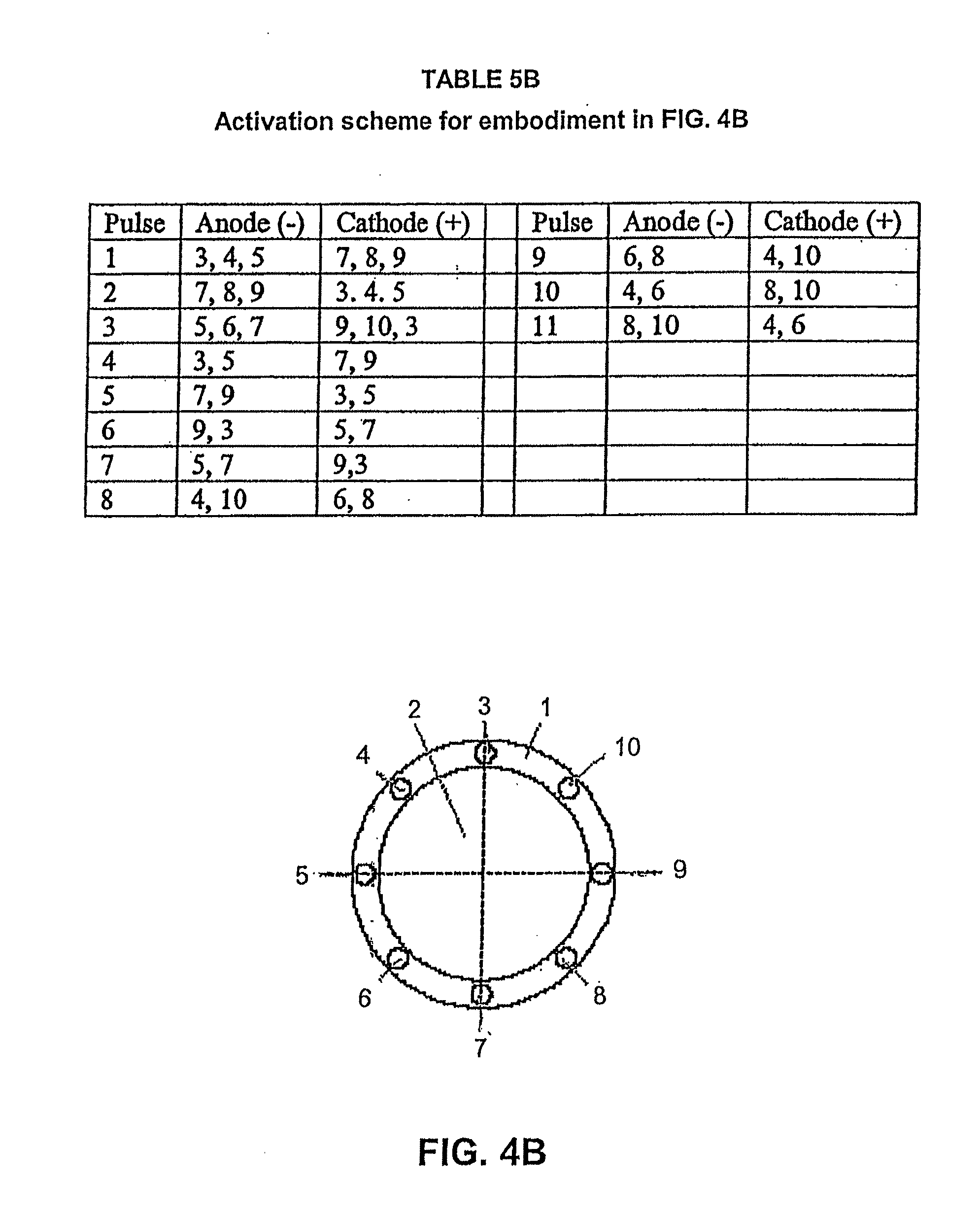
[0044] FIGS. 4A, 4B, 4C, 4D, and 4E are front views of alternative placements of electrodes on the tip of the probe;
[0045] Tables 5A, 5B, 5C, 5D, and 5E are activation schemes associated with the probe arrays shown in FIGS. 4A, 4B, 4C, 4D, and 4E, respectively;
[0046] FIG. 6 is a perspective view of three electrode embodiment of the probe used for intraocular posterior surgery employing the system of the disclosed invention;
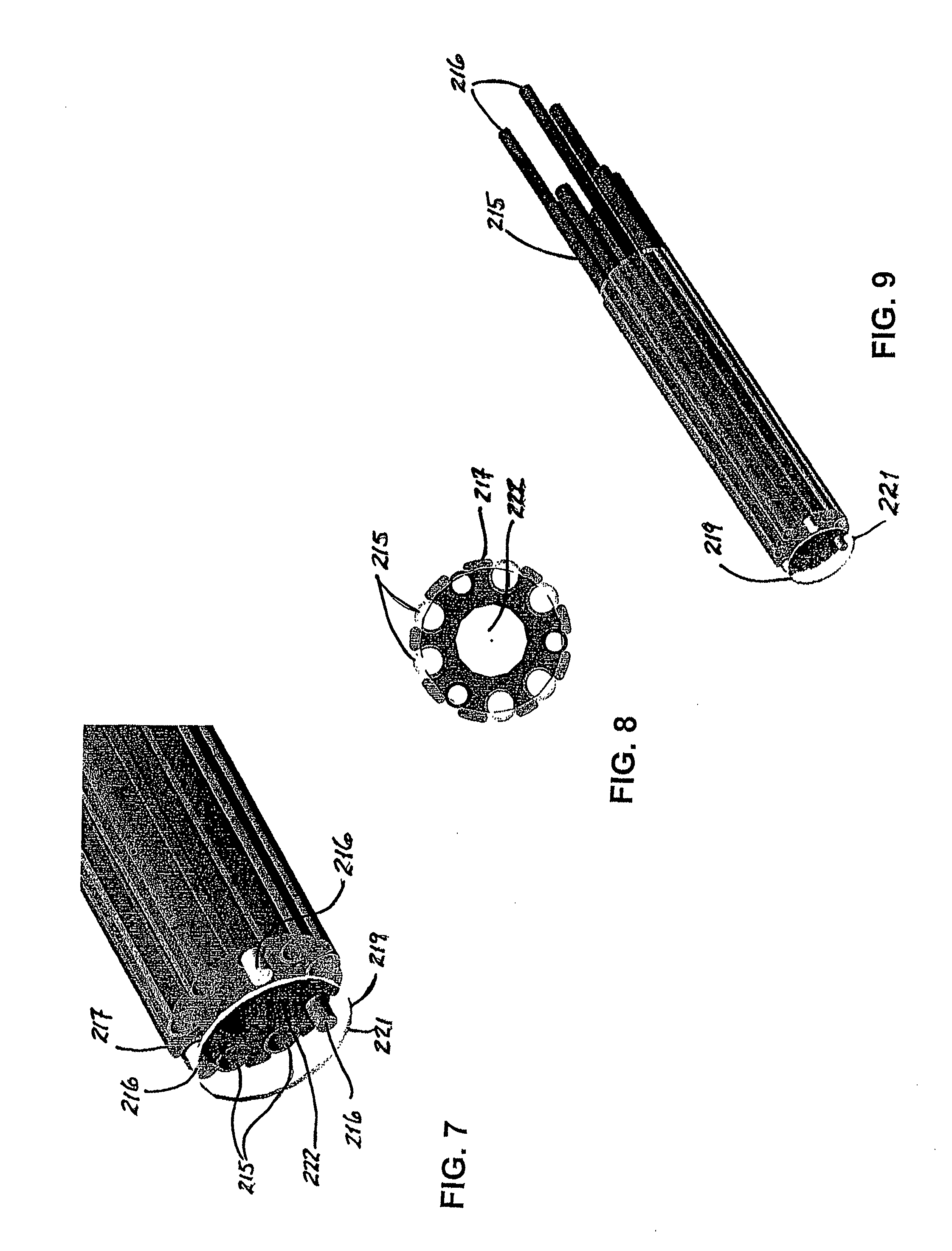
[0047] FIG. 7 is an enlarged perspective view of the tip of the probe shown in FIG. 6 including a transparent cover to reveal the interior features;
[0048] FIG. 8 is an end view of probe shown in FIG. 7;
[0049] FIG. 9 is an expanded perspective view of the probe similar to that shown in FIG. 7;
[0050] FIG. 10 is a schematic diagram of an alternate embodiment of the disclosed system with a supplemental irrigation means included in the probe;
[0051] FIG. 11A is an end view of the probe tip showing the placement of three electrodes as in the embodiment shown in FIGS. 7, 8, and 9;
[0052] FIG. 11B is an end view of a probe tip having four electrodes;
[0053] FIG. 12A is an activation scheme associated with the electrode array shown in FIG. 11A;
[0054] FIG. 12B is an activation scheme associated with the electrode array shown in FIG. 11B;
[0055] FIG. 13A is an illustration of exemplary field lines resulting from placement of a charge on one or more of the electrodes displayed in FIG. 11A;
[0056] FIG. 13B is an illustration of exemplary field lines resulting from placement of a charge on one or more of the electrodes displayed in FIG. 11B;
[0057] FIG. 14 is a schematic diagram of an exemplary three-channel pulse generator used with a three-electrode probe;
[0058] FIG. 15 is a schematic diagram of the channel states during a single cycle of pulsing of the generators shown in FIG. 14;
[0059] FIG. 16 is an enlarged perspective view of another embodiment of the tip of the probe shown in FIG. 6 including a transparent cover to reveal the interior features;
[0060] FIG. 17 is an enlarged perspective view of the probe shown in FIG. 16 including a jacket that covers the interior features;
[0061] FIG. 18 is an end view of probe shown in FIG. 16;
[0062] FIG. 19 is an end view of probe shown in FIG. 17;
[0063] FIG. 20 is an enlarged perspective view of another embodiment of the tip of the probe shown in FIG. 6 including a transparent cover to reveal the interior features;
[0064] FIG. 21 is an enlarged perspective view of the probe shown in FIG. 20 including a jacket that covers the interior features;
[0065] FIG. 22 is an end view of probe shown in FIG. 20; and
[0066] FIG. 23 is an end view of probe shown in FIG. 21.
DETAILED DESCRIPTION OF THE EMBODIMENTS
[0067] Liquefaction (synchysis) is manifested in vitreous portion of the eye as a natural consequence of aging. As an individual reaches 70 to 90 years, roughly 50% of the vitreous gel structure has gone through a change of state or become liquefied. The results of synchysis are realized in the posterior vitreous as a destabilization of the vitreous matrix, dissolution of HA-collagen coupling, unwinding of collagen helices, molecular rearrangements, increases in the volume of liquefied spaces, loosening of entangled tethers, increases in vitreous detachment from the retina, collagen fiber fragmentation and aggregation, and loss of proteoglycans, non-covalent bound macromolecules and adhesive collagen (type IX). At the cellular level, many of the activities leading to liquefaction in the vitreous portion of the eye may be emulated by the present invention.
[0068] The apparatus and method of the disclosed invention deliver a variable direction, pulsed high-intensity and ultrashort duration disruptive electric field (low energy) at a pulse duration, repetition rate, pulse pattern, and pulse train length tuned to the properties of the components of the intraocular extracellular matrix (ECM) to create a short period of tissue dissociation. The recommended modality of ultrashort-pulsed disruptive electric field application relies on the delivery of high powers of low energy.
[0069] As shown in FIG. 1, the disclosed apparatus for implementing the current invention includes a probe assembly 110 which delivers, channels, and distributes the energy applied to the soft tissue in such a fashion as to create a confined, localized, non-thermal dynamic region of electrical forces within a macroscopic volume of the extracellular matrix ECM (e.g., vitreous and intraocular membranes) leading to momentary dissociation of proteinaceous complexes and local liquefaction of the entrained macroscopic volume of tissue. The tip 112 of the hollow probe 114 is positioned to encircle the entrained macroscopic volume of proteinaceous tissue. Fluidic techniques (irrigation) are used first to provide a region of stable impedance and dilution between the electrodes 116 at the tip 112 of the hollow probe 114 and then draw in and remove (aspiration) the affected macroscopic volume of proteinaceous tissue before the reassembly of non-covalent proteinaceous relationships can occur. The fluidic techniques used with the probe assembly 110 may include both saline irrigation and effluent aspiration.
[0070] The directionally changing electrical field created at the tip 112 of the hollow probe 114 is presented substantially perpendicular or orthogonal to the direction of carrier fluid movement (i.e., proteinaceous material in a water solution). The direction of the electrical field is changed with every or nearly every pulse. Pulse duration (nanoseconds) is short, relative to the dielectric relaxation time of protein complexes (.about.1 ms). Multiple pulse direction changes may occur within the dielectric relaxation time interval. Pulse duration, pulse repetition rate, pulse pattern, and pulse train length are chosen to avoid the development of thermal effects ("cold" process). The disclosed system generates and delivers square-shaped pulses of variable direction with fast (<5 nanoseconds) rise time and fall time. The shorter the rise and fall times of the pulse, the higher the frequency components in the Fourier spectrum of the pulse and, consequently, the smaller the structures that can be affected by the pulse. In the system for dissociation and removal of proteinaceous tissue disclosed herein, pulse durations are in the nanosecond range, and the electric field strength would be greater than 1 kV/cm, preferably in the range of hundreds (100s) of kV/cm.
[0071] The apparatus and method which effect the system of the disclosed invention utilize ultrashort chaotic high-intensity pulsed electric field flow fractionation (CHIP EFFF) to engage, dissociate, and remove vitreous and intraocular membranous material. A stepwise continual change in direction of the field (by use of an array of electrodes 116) created by reversing polarity, switching active electrodes or a combination of both is incorporated into the tip 112 of the hollow probe 114 to create a disruptive effect on charges involved in the non-covalent bonds holding the vitreous complexes (groups of proteins) together. By making the macroscopic volume of intraocular electrically unstable tissue, it is possible to further weaken the hydrophobic and hydrostatic bonds within the captured proteinaceous tissue, membranes, and multi-component enzymes, thereby increasing the fluidity or liquefaction of the tissue. The resulting assault on the hydrophobic and hydrostatic bonds of the proteinaceous tissue is sufficient for a momentary compromise of the binding mechanisms of the adhesive macromolecules of the vitreous and associated intraocular tissue, thereby temporarily reducing a minute portion of the bulk vitreous material to a manageable free proteinaceous liquid complex.
[0072] Paramount to the efficacy of the disclosed invention is the choice of energy. The object of the assault on the bonds which hold proteinaceous tissue together is to create disorder among electrons in the outer shell of the macromolecules associated with non-covalent bonds. The preferable form of energy is electricity--energizing electrons by the direct creation of an electric field. Other sources of energy, such as microwaves, and ultrasound which utilize photons and phonons to energize electrons, may also be used to create a disruptive field. It is appreciated herein that lasers, particularly those operating with pulse durations in the femtosecond range and at frequencies substantially at the peak absorption frequency of water, may also be utilized as an alternative energy source.
[0073] In the preferred embodiment of the apparatus and method disclosed herein, a rapid variable direction electric field flow fractionation is used to engage, to dissociate, and to remove vitreous and intraocular membranous material. Specifically, the disclosed system utilizes high-intensity ultrashort-pulsed disruptive electrical field characterized by continuous changes of field direction coupled with fluidic techniques both to facilitate creation of the electrical field and then to remove the proteinaceous dissociated tissue. The high-intensity ultrashort-pulsed disruptive electric field is generated using field strengths on the order of kV/cm with pulse widths on the order of nanoseconds. The high-intensity ultrashort-pulsed disruptive electrical field is kept substantially orthogonal to the direction of aspirating carrier fluid flow. A stepwise continual change in the direction of the high-intensity ultrashort-pulsed disruptive electrical field (created by reversing polarity or switching between an array of electrodes) is adopted to create disorder among the electrons involved in the non-covalent bonds holding the tissue complexes (groups of proteins) together. Using pulse durations and pulse trains that are short with respect to the time required for thermal effects, the assault on the tissue-binding mechanisms is essentially a "cold" process and sufficient for momentary tissue matrix dissociation. The assault on the tissue-binding mechanisms will compromise the binding mechanisms of the adhesive macromolecules of the vitreous and associated intraocular tissue, thereby temporarily reducing a minute portion of the bulk vitreous material to a manageable proteinaceous liquid complex. The strength of the electrical field causing the disassociation obeys the inverse square law. As such, the strength of the field is highest in region between electrodes. In the preferred embodiment, this distance is less than 0.5 millimeters. The affected proteinaceous liquid complex is localized within the region of applied pulsed rapid variable direction electrical field between probe electrodes and is removed using fluidic techniques (aspiration) before the transient effects of the assault on the tissue-binding mechanism expire (relax). Once the volume of proteinaceous tissue is in the extraction channel (i.e., within the fluidic aspiration stream), the state of the altered proteinaceous complex may return to a quasi pre-assault state.
[0074] The disclosed exemplary application of the system described herein is for the treatment of pathologic retinal conditions whereby, as shown in FIG. 1, a hollow probe 114, as described herein, using a handle 120 is inserted by a surgeon into the posterior region of the eye 100 via a pars plana approach 101, as shown in FIG. 3. Using standard visualization process, vitreous and/or intraocular membranes and tissues would be engaged by the tip 112 of the hollow probe 114, irrigation 130 and aspiration 140 mechanisms would be activated, and ultrashort high-intensity pulsed electric power from a high voltage pulse generator 150 would be delivered through a pulse-forming network 160, switching circuit 170, and cable 124, creating a disruptive high-intensity ultrashort-pulsed electrical field within the entrained volume of tissue. The adhesive mechanisms of the entrained constituents of the tissue that are drawn toward the probe tip 112 via aspiration through an aspiration line 118 connected to an aspiration lumen, 122 in the hollow probe 114 would be dissociated, and the fluidic techniques employed would remove the disrupted tissue. Engagement may be axial to or lateral to the tip 112 of the hollow probe 114. Extracted tissue would be removed through the aspiration lumen 122 via a saline aspiration carrier to a distally located collection module.
[0075] All of the posterior vitreous tissue could be removed, or just specific detachments of vitreous tissue from the retina or other intraocular tissues or membranes could be realized.
[0076] Engagement disruption and removal of vitreous tissue, vitreoretinal membranes, and fibrovascular membranes from the posterior cavity of the eye and surfaces of the retina are the critical processes pursued by vitreoretinal specialists, in order to surgically treat sight-threatening conditions, such as diabetic retinopathy, retinal detachment, proliferative vitreoretinopathy, traction of modalities, penetrating trauma, epi-macular membranes, and other retinopathologies.
[0077] Though intended for posterior intraocular surgery involving the vitreous and retina, it can be appreciated that the device and modality described herein is applicable to anterior ophthalmic treatments as well, including traction reduction (partial vitrectomy); micelle adhesion reduction; trabecular meshwork disruption, manipulation, reorganization, and/or stimulation; trabeculoplasty to treat chronic glaucoma; Schlemm's Canal manipulation, removal of residual lens epithelium, and removal of tissue trailers. Applicability of the disclosed apparatus and method to other medical treatments will become obvious to one skilled in the art.
Parts of System:
[0078] Control Unit (180) [0079] Pulse Power Generator (150) [0080] Pulse-Forming Network (160) [0081] Switching Circuit (170) [0082] Transmission Line (124) [0083] Multi-Electrode Surgical Probe Assembly (110) [0084] Fluidics System (130, 140)
[0085] The apparatus and method of the disclosed invention deliver pulsed high-intensity and ultrashort duration electrical field (low energy) at a pulse duration, repetition rate, pulse pattern, and pulse train length tuned to the properties of the components of the intraocular extracellular matrix (ECM). The pulse power generator 150 for the system 190 delivers pulsed DC or gated AC against a low impedance of vitreous and the irrigating solution. Included in the system 190 are energy storage, pulse shaping, transmission, and load-matching components. The peak output voltage of the high voltage generator 150 is sufficient to deliver up to a 300 kV/cm field strength using the electrodes 116 at the distal end 112 of the hollow surgical probe 114. Pulse duration would be short relative to the dielectric relaxation time of protein complexes. Also, pulse duration, repetition rate, and pulse train length (i.e., duty cycle) are chosen to avoid the development of thermal effects ("cold" process). The system 190 generates and delivers square-shaped pulses with a fast (<5 nanoseconds) rise time and fall time. In the apparatus and method disclosed herein, pulse durations would be in the nanosecond range, and the voltage would be greater than one (1) kV and preferably in the range of tens (10s) of kV.
[0086] A switching circuit 170 is incorporated to control pulse duration, repetition rate, and generate a stepwise continual change in the direction of the electrical field by switching between electrodes, reversing polarity between electrodes or a combination of both in an array of electrodes at the tip 112 of the hollow probe 114, thus creating disorder in the electric field without causing dielectric breakdown of the carrier fluid between the electrodes or thermal effects.
[0087] Paramount to the effectiveness of the disclosed invention is the choice of energy. The object is to create disorder among electrons in the outer shell of macromolecules associated with non-covalent bonds binding proteinaceous complexes together. The preferable form of energy is electricity--energizing electrons by the direct creation of an electrical field. Sources of energy, such as microwaves, laser, and ultrasound, which utilize photons and phonons to energize electrons may also be used to create the desired disorder among the electrons in the outer shell of macromolecules.
[0088] The disclosed apparatus includes a transmission line 124 and a hollow surgical probe 114 which delivers, channels, and distributes the applied energy in such a fashion as to create a confined, localized region of electrical force within a macroscopic volume of the extracellular matrix ECM (e.g., vitreous and intraocular membranes). The electrical field is presented essentially perpendicularly or orthogonally to the direction of carrier fluid movement (i.e., proteinaceous material in a water solution). FIGS. 4A, 4B, 4C, 4D, and 4E illustrate several possible electrode array embodiments at the distal end 112 of the surgical probe 114.
[0089] For example, reference number 1 is used in FIGS. 4A, 4B, 4C, 4D, and 4E to refer to a polymer extrusion with one or more through lumens. Reference number 2 designates the lumen for aspirated fluid flow. Reference numbers 3, 4, 5, 6, 7, 8, 9, and 10 refer to the electrode wires embedded in extrusion 1. In FIGS. 4A, 4C, and 4D, a centrally located electrode wire 11 is used. In FIG. 4E, a centrally located tubular electrode 12 is used. Also in FIG. 4E, a centrally located lumen 13 is used for fiberoptic equipment or some other form of instrumentation. Those of ordinary skill in the art will understand that numerous other configurations are possible to generate the desired pulsed rapid strong electrical field pattern. Though shown in a substantially planar fashion, the distal face of each electrode 116 may be axially staggered or aligned and may be either inset or protruding, or a combination of both, from the distal end 112 of the hollow probe 114. Though shown terminating in a plane perpendicular to the axial direction of the probe shaft, the electrodes 116 may terminate axially about a lateral window (not shown).
[0090] In the preferred embodiment, the outside diameter of the extrusion 1 is less than 0.040 inches. It is envisioned that vitreous or intraocular tissue material would be drawn toward and into the aspiration channel(s), and, as the material approached the region orthogonal to the electrodes 116, the electrodes would be activated, creating an ultrashort, high-intensity disruptive electric field between electrodes 116.
[0091] Variable field projections with constantly changing direction would result from the placement and sequential activation of arrays of electrodes. Tables 5A, 5B, 5C, 5D, and 5E illustrate a plan of electrode activation for the embodiments shown in FIGS. 4A, 4B, 4C, 4D, and 4E, respectively. In Table 5A, there are 12 pulses that are illustrative of a pulse sequence used on the embodiment of the end of the probe 114 shown in FIG. 4A. The first pulse utilizes the electrode 116, given reference number 11, as an anode, and the cathodes are 3, 4, 5. The second pulse is just the opposite. The remaining pulses are illustrative of a pulse arrangement to establish a variable direction electrical filed.
[0092] In Table 5B, there are 11 pulses that are illustrative of a pulse sequence used on the embodiment of the probe 114 shown in FIG. 4B.
[0093] In Table 5C, a 12-pulse sequence is shown as in FIG. 5A for use on the probe shown in FIG. 4C.
[0094] In Tables 5D and 5E, a 10-pulse sequence is shown for the probes shown in FIGS. 4D and 4E, respectively. Numerous other field patterns are envisioned, depending on the embodiment and the sequence of electrode activation. The object of the electrode activation is to utilize the polar properties of water and protein, create disorder with rapidly changing high-intensity electric field direction, and thus induce conformal changes of both water and protein, leading to momentary tissue dissociation. The dissociated tissue complex localized within the region of applied electrical field is then removed using concurrent fluidic techniques before the transient effects of the assault expire (relax).
[0095] In the case of embodiment 4E, the central electrode 12 may be a tubular conductive electrode with a center region 13. The central region 13 could be a through lumen for an irrigation or instrument channel, or the central region could be a fiber-optic device for delivery of light.
[0096] As previously stated, the position of electrodes in the arrays and the number of electrodes may be configured to present the most efficacious disruptive electric fields. The electrodes may also be axially positioned so that one or more of the electrodes does not terminate at the same length or same axial position. The terminal end of the electrodes may be shaped in such a fashion as to optimize spatial field strength between the electrodes. Shapes of the terminal end of the electrodes may include straight edges, corners, sharps, curvatures (constant and variable) or combinations thereof chosen to project and optimize electric field strength distribution between the electrodes.
[0097] Fluidic techniques (aspiration) are included to draw in and remove the dissociated tissue volume before reassembly of non-covalent proteinaceous relationships can occur. The fluidic techniques used in the preferred embodiment include both saline irrigation and effluent aspiration. In the preferred embodiment, the fluidics system includes irrigation and aspiration features which are uniquely matched such that the volume and pressure within the eye are maintained within physiological limits. The posterior vitreous contains more than 97% water, and an important function of the fluidics system is to ensure dilution, hydration and stable impedance of engaged material. In the preferred embodiment, the aspiration channel is incorporated into the hollow surgical probe 114 such that intraocular tissues are drawn into the aspiration lumen 122 or channels while being subjected to the disruptive electric field described above. The volume flow rate of the aspirated effluent is matched to the dissociation rate of the hydrated proteinaceous material under the influence of the disruptive electric field. It is anticipated that irrigation with BSS.RTM. irrigating solution or BSS PLUS.RTM. irrigating solution, both available from Alcon Laboratories, Inc., will be utilized. Innocuous properties and ingredients may be incorporated into the irrigation fluid to enhance dissociation. The irrigation route/channel may be incorporated into the surgical probe, as illustrated in FIG. 4E, it may be provided in an independent cannula, or it may be provided by a combination of both means.
[0098] FIG. 6 is a perspective of an alternate embodiment of a probe assembly 210 including three electrodes. As in the preferred embodiment 110, the probe assembly 210 includes a hollow probe 214 and a handle 220. Tissue would be engaged by the tip 212 of the hollow probe 214. A better understanding of probe assembly 210 may be had by reference to FIGS. 6, 7, and 8. The three electrodes 216 are positioned at substantially equal angular intervals around a central spine 217 within the probe 214. Between the electrodes 216 are the irrigation channels 215. In the center of the central spine 217 is located an aspiration lumen 222. Covering the central spine 217, the irrigation channels 215, and the electrodes is an external jacket 219 which terminates in an atraumatic tip 221. The probe assembly 210 is positioned so that the tissue to be removed is located just inside the atraumatic tip 221.
[0099] The support system 290 for probe assembly 210, shown in FIG. 10, is similar to that of the preferred embodiment shown in FIG. 3 but for the inclusion of a probe tip irrigation system 235. Included is a global irrigation system 230, an aspiration system 240 connected to an aspiration line 218, a control unit 280, one or more high-voltage pulse generators 250, a switching circuit 270 connected to a transmission line 224, and a probe tip diluting irrigation system 235 connected to a probe tip irrigation tube 237.
[0100] As in FIGS. 4A, 4B, 4C, 4D, and 4E which display the electrodes at the probe tip, FIGS. 11A and 11B illustrate alternate arrangements of electrodes 1, 2, 3, and 4 in the probe assembly 210. FIGS. 12A and 12B correspond to FIGS. 11A and 11B showing exemplary sequences of electrode activation to create the non-plasma, non-contact energized disruptive region around the proteinaceous tissue. To better understand the creation of this non-plasma, non-contact energized disruptive region, FIGS. 13A and 13B illustrate the field lines for the sequence of pulses illustrated in FIGS. 12A and 12B, respectively, where the polarity of the electrodes is not reversed.
[0101] FIG. 14 is a schematic diagram of the three-channel pulse generator 250 which controls the duration of individual pulses, the repetition rate of the individual pulses, and the pulse length of the pulse train.
[0102] FIG. 15 is a table illustrating the channel states of an exemplary single cycle of pulsing of the three-channel pulse generator 250 shown in FIG. 14.
[0103] A still better understanding of the system 290, shown in FIG. 10, may be had by understanding that the probe assembly 210 includes a plurality of through lumens 215 for supplemental irrigation, as shown in FIGS. 6, 7, 8, and 9, respectively. The flow rate of irrigation is less than the aspiration rate through the central lumen 222, such that the escape velocity of the supplemental irrigation fluid is less than the entrance velocity of diluted hydrated intraocular tissue. Additional irrigation fluid is presented by probe tip diluting irrigation mechanism 235 which is external to the probe (FIG. 10). The irrigation fluid is used both to dilute intraocular tissue and to maintain a stable or near constant impedance between the electrodes 216, thereby avoiding significant shifts in realized energy delivery and field strength. Properties of the irrigation fluid such as pH and ingredients may be chosen to enhance vitreous dissociation.
[0104] A third conduit for irrigation 237 connects the probe assembly 210 to the supplemental irrigation source 235. Also to be noted, in FIG. 10, the pulse forming network is incorporated into the high voltage pulse generator 250.
[0105] By reference to FIGS. 11A and 12A, it may be seen that, in lieu of reversing polarity of the electrodes 216 between pulses, the active anodes and cathodes are switched between the electrodes. The field lines created are shown in FIG. 13A to illustrate an example of an electric field for each pulse. For the three electrode 1, 2, and 3 configuration, shown in FIG. 11A, a single cycle includes three pulses emanating from different directions. In the table at FIG. 12A, sequencing examples are shown for cases involving electrode switching and not actual polarity (reversal). The table at FIG. 12B and the field lines shown in FIG. 13B illustrate the possible four-electrode embodiment 1, 2, 3, and 4, shown in FIG. 11B, where the electrodes act in pairs as anodes and cathodes.
[0106] The three-channel pulse generator, whose schematic is illustrated in FIG. 14, shows that the triggering of one channel sends a pulse to an electrode, then triggers a second channel which, in turn, sends a pulse to a different electrode, then triggers the third channel which, in turn, sends a pulse to a different electrode and triggers the first channel to start the sequence over again. As one channel fires a pulse, the other two channels offer zero resistance and act as return circuits for the fired pulse. The sequencing of channels may be ordered, or it may be random.
[0107] FIG. 15 illustrates the polarity condition of each channel during a pulse firing. The polarity condition of each channel results from electrode switching as opposed to actual polarity switching on any single channel.
[0108] A further embodiment of probe assembly 210 is pictured in FIGS. 16-23. FIGS. 16-19 depict an embodiment with electrodes 216 that are flattened and axially elongated. These electrodes 216 are flattened with the large flat portion aligned radially with respect to the aspiration channel 222. The sharp corners of electrodes 216 allow for a more intensely focused electric field to be produced at the aspiration channel 222. These electrodes 216 terminate at the orifice of jacket 219.
[0109] FIGS. 20-23 depict an embodiment with electrodes 216 that have pointed tips. These electrodes 216 are flattened with the large flat portion aligned radially with respect to the aspiration channel 222. These electrodes 216 terminate in a folded pointed tip with the pints directed radially inward toward the aspiration channel 222. The sharp corners of electrodes 216 allow for a more intensely focused electric field to be produced at the aspiration channel 222.
[0110] In the two embodiments depicted in FIGS. 16-23, the three electrodes 216 are positioned at substantially equal angular intervals around a central spine 217 within the probe 214. Between the electrodes 216 are the irrigation channels 215. In the center of the central spine 217 is located an aspiration lumen 222. Covering the central spine 217, the irrigation channels 215, and the electrodes is an external jacket 219 which terminates in an atraumatic tip 221. The probe assembly 210 is positioned so that the tissue to be removed is located just inside the atraumatic tip 221. In FIGS. 17, 19, 21, and 23, an opening 227 between the jacket 219 and the aspiration channel 222 allows irrigation fluid to pass in a waterfall effect near the electrodes 216.
[0111] The operation of the probe assembly of FIGS. 16-23 is similar to that depicted in FIGS. 11A, 12A, and 13A. Other modes of operation previously described are also appropriate with the assembly of FIGS. 16-23.
[0112] The disclosed system provides the following advantages:
[0113] a) Traction-free removal of intraocular tissues from the posterior segment of the eye.
[0114] b) Manageable dissociation of small volumes of tissue with no far-field effect.
[0115] Specifically, there is no far-field migration, leakage, or scattering of the electrical field. Unlike enzymatic processes which affect the entire posterior of the eye, including the retina, the effect of the disclosed CHIP EFFF is localized.
[0116] c) Partial vitrectomy or traction release without total vitrectomy.
[0117] Most vitreoretinal surgical applications required extraction of all the vitreous in the posterior of the eye. Using the disclosed system, it is possible to selectively detach proteinaceous tissue and collagen from the retinal membrane without removing all the vitreous. Accordingly, the need for post-surgical artificial vitreous is eliminated.
[0118] d) No reactive oxygen species is created.
[0119] As opposed to ablative technologies, such as lasers, plasmas, and thermal-generating modalities, the disclosed system affects only the non-covalent adhesion aspects of the vitreous and intraocular membranes; therefore, no toxic chemicals or ROS are induced or released. Insufficient energy is delivered to cause thermal events.
[0120] e) Safety.
[0121] Discontinuation of energy delivery results in reassembly of proteinaceous tissue. Thus, the disclosed method can be discontinued almost instantaneously at any time without permanent damage to target tissue.
[0122] f) Multimodal (extract, coagulate, cut, stimulate).
[0123] Since the probe has a plurality of electrodes, it is possible to change power settings to achieve different functional results. In the CHIP EFFF mode, the probe would be utilized to extract vitreous and intraocular membranes. In the coagulator mode, RF energy could be applied in order to stop vascular hemorrhage. In a cut mode, RF energy at the appropriate power and frequency could be applied as to actually create a plasma or spark erosion to effect cutting of tissue. In the stimulate mode, an electrical pulse of lower power could be delivered for therapeutic purposes.
[0124] g) Reduction in instrument exchange.
[0125] In posterior ocular surgery, an abundant number of custom and specialized instruments are required to engage, tease, separate, and remove vitreous and intraocular membranous material. Instrument exchange during surgery is a major factor in post-operation complications. Use of this disclosed invention renders many prior-art instruments obsolete and minimizes instrument exchange.
[0126] h) No moving parts.
[0127] Reduction in cost and labor for probe fabrication is realized. Fabrication of mechanical vitrectomy probes is labor-intensive. The disposable hollow probe perceived herein consists of a small handle with an attached multi-lumen co-extrusion or assemblies with wires in the lumens or crevices. Skill in assembly compared to current mechanical assemblies is reduced.
[0128] i) Posterior and anterior applications.
[0129] While designed for tractionless removal of vitreous and intraocular tissues, the disclosed apparatus may be utilized for certain anterior segment surgeries, such as trabecular meshwork stimulation, removal of residual lens epithelium, and removal of tissue trailers, anterior vitrectomy, among others.
[0130] j) Hybrid-friendly.
[0131] The simplicity of design in the disclosed probe assembly makes it useful as stand-alone or an adjunct to other tissue disruption and extraction means, such as mechanical vitrectomy, AquaLase.RTM. surgical instruments, available from Alcon Laboratories, Inc., and chemical vitrectomy (enzymatic action).
[0132] While the disclosed invention has been described in terms of its preferred and alternate embodiments, those of ordinary skill in the art will realize that still other embodiments have been enabled by the foregoing disclosure.
* * * * *
D00000
D00001
D00002
D00003
D00004
D00005
D00006
D00007
D00008
D00009
D00010
D00011
D00012

D00013

D00014
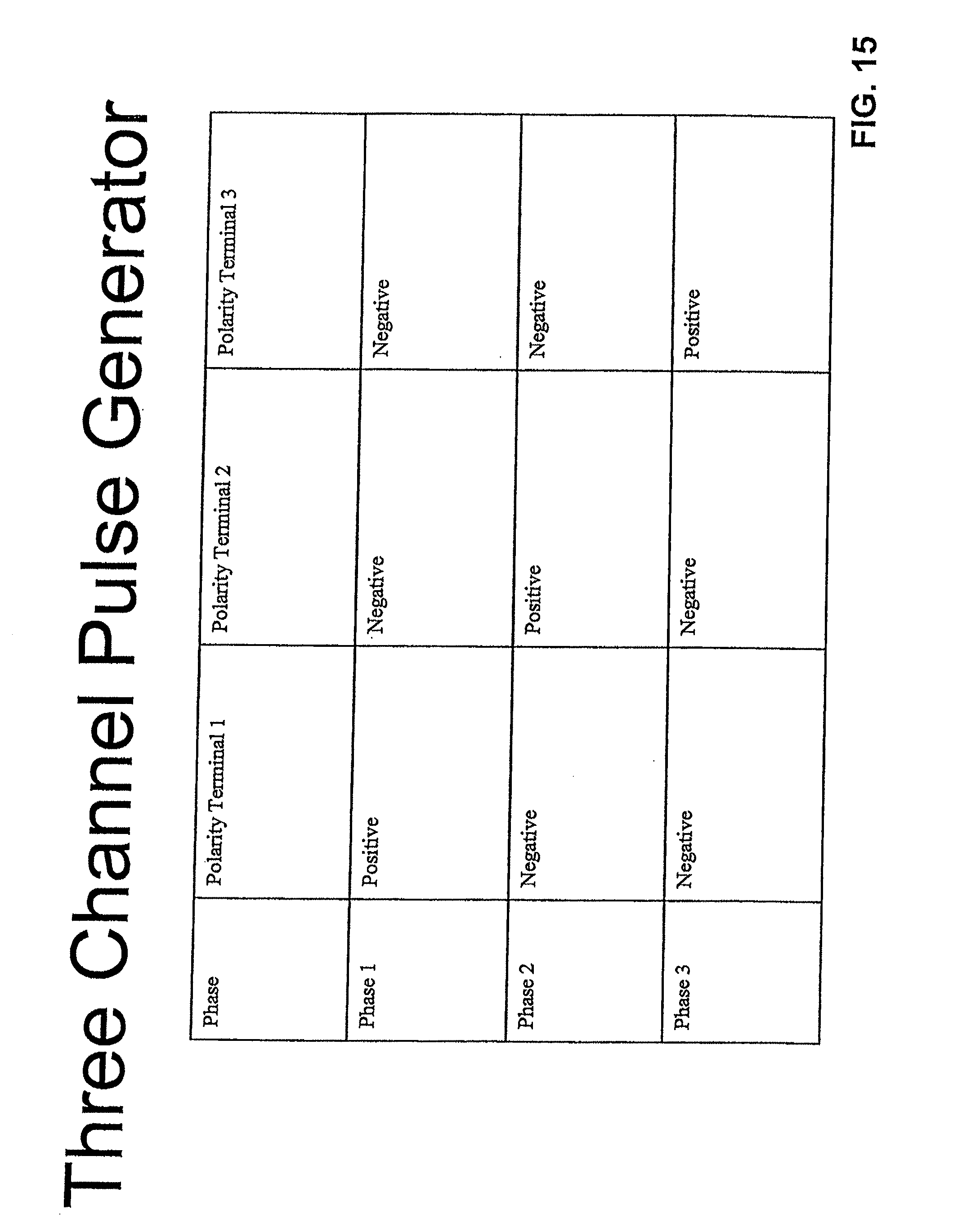
D00015

D00016

D00017

D00018

XML
uspto.report is an independent third-party trademark research tool that is not affiliated, endorsed, or sponsored by the United States Patent and Trademark Office (USPTO) or any other governmental organization. The information provided by uspto.report is based on publicly available data at the time of writing and is intended for informational purposes only.
While we strive to provide accurate and up-to-date information, we do not guarantee the accuracy, completeness, reliability, or suitability of the information displayed on this site. The use of this site is at your own risk. Any reliance you place on such information is therefore strictly at your own risk.
All official trademark data, including owner information, should be verified by visiting the official USPTO website at www.uspto.gov. This site is not intended to replace professional legal advice and should not be used as a substitute for consulting with a legal professional who is knowledgeable about trademark law.