Proximally Trimmable Catheter Including Pre-attached Bifurcation And Related Methods
Blanchard; Daniel B.
U.S. patent application number 12/823663 was filed with the patent office on 2010-12-30 for proximally trimmable catheter including pre-attached bifurcation and related methods. This patent application is currently assigned to C. R. Bard, Inc.. Invention is credited to Daniel B. Blanchard.
| Application Number | 20100331823 12/823663 |
| Document ID | / |
| Family ID | 43381532 |
| Filed Date | 2010-12-30 |


View All Diagrams
| United States Patent Application | 20100331823 |
| Kind Code | A1 |
| Blanchard; Daniel B. | December 30, 2010 |
PROXIMALLY TRIMMABLE CATHETER INCLUDING PRE-ATTACHED BIFURCATION AND RELATED METHODS
Abstract
A proximally trimmable catheter is disclosed. In one embodiment, the catheter includes a multi-lumen catheter tube, one or more extension tubes, and a hub for fluidly connecting the two. In a first unlocked state, the hub is axially slidable along the catheter tube. The hub includes tube pins that are in fluid communication with the extension tubes. A cutting member is positioned to longitudinally cut the catheter tube during axial sliding of the hub along the catheter tube such that distal portions of the tube pins remain disposed within the lumens of the catheter tube. When positioned as desired, the hub is locked into a second locked state and is no longer axially slidable along the catheter tube. The tube pins are fluidly sealed within the lumens of the catheter tube as to establish fluid communication between the extension tubes and the lumens via the tube pins.
| Inventors: | Blanchard; Daniel B.; (Bountiful, UT) |
| Correspondence Address: |
    Rutan & Tucker, LLP.
    611 ANTON BLVD, SUITE 1400
    COSTA MESA
    CA
    92626
    US
|
| Assignee: | C. R. Bard, Inc. Murray Hill NJ |
| Family ID: | 43381532 |
| Appl. No.: | 12/823663 |
| Filed: | June 25, 2010 |
Related U.S. Patent Documents
| Application Number | Filing Date | Patent Number | ||
|---|---|---|---|---|
| 61220943 | Jun 26, 2009 | |||
| Current U.S. Class: | 604/533 |
| Current CPC Class: | A61M 39/105 20130101; A61M 2025/0037 20130101; A61M 39/12 20130101; A61M 25/0097 20130101; A61M 25/0014 20130101 |
| Class at Publication: | 604/533 |
| International Class: | A61M 25/18 20060101 A61M025/18 |
Claims
1. A tubular medical device for placement of a portion thereof into a body of a patient, the medical device, comprising: an elongate tube defining at least one lumen; at least one extension tube; and a hub for placing the at least one extension tube in fluid communication with the at least one lumen of the elongate tube, the hub being axially slidable along the elongate tube in a first unlocked state, the hub including: at least one tube pin in fluid communication with the at least one extension tube; means for cutting a proximal portion of the elongate tube such that a portion of the at least one tube pin remains within an uncut portion of the at least one lumen during sliding of the hub along the elongate tube, the means for cutting being at least temporarily included with the hub; and means for fluidly sealing the at least one tube pin within the at least one lumen when the hub is locked into a second locked state such that the hub is no longer slidable along the elongate tube and such that the at least one extension tube is in fluid communication with the at least one lumen of the elongate tube via the at least one tube pin.
2. The tubular medical device as defined in claim 1, wherein the means for fluidly sealing compressively seals an interface of the at least one tube pin within the at least one lumen.
3. The tubular medical device as defined in claim 2, wherein the means for fluidly sealing includes at least one annular compression washer disposed about the catheter tube proximate the interface of the at least one tube pin within the at least one lumen, the at least one compression washer being invertible between first and second positions, an inner diameter of the at least one compression washer being relatively smaller in the second position than in the first position.
4. The tubular medical device as defined in claim 1, wherein the means for cutting is included with an assembly tool disposed about the hub during placement thereof, the means for cutting being removable from the assembly tool.
5. The tubular medical device as defined in claim 1, wherein the means for cutting splits the elongate tube into at least two longitudinal pieces.
6. A catheter, comprising: an elongate catheter tube defining at least one lumen; at least one extension tube; and a hub for placing the at least one extension tube in fluid communication with the at least one lumen of the catheter tube, the hub being axially slidable along the catheter tube when in a first unlocked state, the hub including: at least one tube pin in fluid communication with the at least one extension tube; and a first cutting member at least temporarily included with the hub for longitudinally cutting the catheter tube during axial sliding of the hub along the catheter tube such that a distal portion of the at least one tube pin remains disposed within the at least one lumen of an uncut portion of the catheter tube, wherein the hub is lockable into a second locked state such that the hub is no longer axially slidable along the catheter tube and the at least one extension tube is in fluid communication with the at least one lumen of the catheter tube via the at least one tube pin.
7. The catheter as defined in claim 6, further comprising: a compression element to fluidly seal the at least one tube pin within the at least one lumen.
8. The catheter as defined in claim 7, wherein the compression element includes an invertible compression washer.
9. The catheter as defined in claim 7, wherein the hub includes a distal hub portion and a proximal hub portion, wherein the compression element is initially included with the proximal hub portion, and wherein the distal and proximal hub portions include latching features for engaging one another when the hub is placed into the second locked state.
10. The catheter as defined in claim 6, wherein the first cutting member includes a blade positioned proximal to at least a portion of the at least one tube pin, and wherein the first cutting member is removable from the hub after use.
11. The catheter as defined in claim 6, further comprising: a second cutting member for trimming a proximal portion of the catheter after the hub is positioned in a desired location on the catheter tube, wherein the first and second cutting members are included with an assembly tool, the assembly tool removably attached to the hub.
12. A method for proximally trimming a catheter, the catheter including an elongate catheter tube defining at least one lumen, the method comprising: placing at least a distal portion of the catheter tube within a body of a patient; sliding a hub in a distal direction along the catheter tube, the catheter tube received by a conduit of the hub, the hub including at least one tube pin including a portion that remains within the at least one lumen of the catheter tube during the sliding of the hub; and sealing an interface between the at least one tube pin and the at least one lumen after the hub is disposed at a desired position such that fluid communication is established between the at least one lumen of the catheter tube and at least one extension tube of the catheter via the at least one tube pin.
13. The method for proximally trimming as defined in claim 12, wherein sliding the hub further comprises: axially cutting a proximal portion of the catheter tube as the hub is slid along the catheter tube such that the at least one tube pin remains within the at least one lumen.
14. The method for proximally trimming as defined in claim 12, wherein the hub includes a distal hub portion and a proximal hub portion, wherein the distal and proximal hub portions are unlocked with respect to one another during sliding of the hub, and wherein the method further comprises: locking the distal and proximal hub portions together after the hub is disposed at the desired position.
15. The method for proximally trimming as defined in claim 14, wherein locking the distal and proximal hub portions together further includes actuating at least one lever component to lock the hub portions together and wherein locking the distal and proximal hub portions together further causes the sealing of the interface between the at least one tube pin and the at least one lumen of the catheter tube.
16. The method for proximally trimming as defined in claim 15, wherein sealing the interface further comprises: compressing the interface between the at least one tube pin and the at least one lumen with a compression component included with the proximal hub portion.
17. A catheter, comprising: an elongate catheter tube defining a plurality of lumens; a hub including a distal hub portion and a proximal hub portion, the distal and proximal hub portions defining a conduit through which the catheter tube is received; a plurality of extension tubes; a plurality of tube pins included with the hub assembly, each tube pin being in fluid communication with a corresponding one of the extension tubes; and an assembly tool removably included with the hub and including: a first cutting member positioned to cut a proximal portion of the catheter tube along a length thereof as the hub is moved distally along the catheter tube such that a portion of each of the tube pins remains disposed within an uncut portion of a respective one of the lumens of the catheter tube and such each extension tube is in fluid communication with at least one of the lumens of the catheter tube; and at least one lever component for locking the distal and proximal hub portions together to prevent further movement of the hub along the catheter tube after the hub is positioned in a desired location.
18. The catheter as defined in claim 17, further comprising an annular compression element for fluidly sealing an interface between the plurality of tube pins and the lumens of the catheter tube, the compression element component including at least one invertible compression washer disposed about the catheter tube, wherein inversion of the at least one compression washer is at least partially actuated by actuation of the at least one lever component.
19. The catheter as defined in claim 18, wherein the at least one lever component includes two lever arms hingedly connected to the assembly tool, each lever arm including an engagement surface for engaging a portion of the proximal hub portion during locking with the distal hub portion.
20. The catheter as defined in claim 19, wherein the assembly tool includes a second cutting member for removing portions from the catheter tube already cut by the first cutting member, the first and second cutting members included in a cutting member housing that is removable from the assembly tool.
21. A method for proximally trimming a catheter after insertion thereof into a patient, the catheter including a catheter tube defining at least one lumen, the method comprising: longitudinally cutting a proximal portion of the catheter tube during advancement of a hub distally along the catheter tube such that a portion of a tube pin of the hub for providing fluid access to the at least one lumen remains within the at least one lumen during advancement of the hub; and sealing an interface between the tube pin and the at least one lumen of the catheter tube.
Description
CROSS-REFERENCE TO RELATED APPLICATIONS
[0001] This application claims the benefit of U.S. Provisional Patent Application No. 61/220,943, filed Jun. 26, 2009, and entitled "Direct Placement Catheter and Method of Use," which is incorporated herein by reference in its entirety.
BRIEF SUMMARY
[0002] Briefly summarized, embodiments of the present invention are directed to a proximally trimmable catheter. In one embodiment, the catheter includes a multi-lumen catheter tube, a set of one or more extension tubes, and a hub for fluidly connecting the two. In a first unlocked state, the hub is axially slidable along the catheter tube. The hub includes one more tube pins that are in fluid communication with the extension tubes.
[0003] A cutting member is positioned to longitudinally cut the catheter tube during axial sliding of the hub along the catheter tube such that distal portions of the tube pins remain disposed within the lumens of the uncut portion of the catheter tube distal to the cutting member.
[0004] When positioned as desired, the hub can be locked into a second locked state such that it is no longer axially slidable along the catheter tube. The tube pins are fluidly sealed within the lumens of the catheter tube by a compression component or other suitable element as to establish fluid communication between the extension tubes and the lumens of the catheter tube via the tube pins.
[0005] These and other features of embodiments of the present invention will become more fully apparent from the following description and appended claims, or may be learned by the practice of embodiments of the invention as set forth hereinafter.
BRIEF DESCRIPTION OF THE DRAWINGS
[0006] A more particular description of the present disclosure will be rendered by reference to specific embodiments thereof that are illustrated in the appended drawings. It is appreciated that these drawings depict only typical embodiments of the invention and are therefore not to be considered limiting of its scope. Example embodiments of the invention will be described and explained with additional specificity and detail through the use of the accompanying drawings in which:
[0007] FIG. 1 is a simplified view of a catheter positioned in a body of a patient, showing one possible environment for practice of an embodiment of the present invention;
[0008] FIG. 2 is a perspective view of a catheter including a hub in a first unlocked state and configured in accordance with one embodiment;
[0009] FIGS. 3A-3F are various views of a distal portion of the hub of FIG. 2;
[0010] FIGS. 4A-4F are various views of a proximal portion of the hub of FIG. 2;
[0011] FIG. 5 is a cross sectional view of the proximal hub portion taken along the line 5-5 in FIG. 4F;
[0012] FIGS. 6A-6B are various views of a cutting member positioned with respect to the proximal hub portion;
[0013] FIGS. 7A-7C are cross sectional views of a catheter showing possible cutting thereof by a cutting member according to one embodiment;
[0014] FIGS. 8A-8E are various views of an assembly tool for use with the hub of FIG. 2 according to one embodiment; and
[0015] FIGS. 9A-9D are various views of use of the hub and assembly tool of FIGS. 8A-8E in placing and trimming a catheter.
DETAILED DESCRIPTION OF SELECTED EMBODIMENTS
[0016] Reference will now be made to figures wherein like structures will be provided with like reference designations. It is understood that the drawings are diagrammatic and schematic representations of exemplary embodiments of the invention, and are not limiting of the present invention nor are they necessarily drawn to scale.
[0017] FIGS. 1-9D depict embodiments of the present invention, which are generally directed to a proximally trimmable catheter for use in gaining access to a body of a patient, such as access to a patient's vasculature, for instance. The catheter includes a catheter tube defining one or more lumens and a hub. The hub is configured to be distally slid along the length of the catheter tube. So configured, the hub can be positioned as desired along the length of the catheter tube with respect to the insertion site of the catheter. Once positioned as desired, the hub can be locked into position and establish fluid communication between the lumen(s) of the catheter tube and one or more extension legs of the catheter.
[0018] FIG. 1 depicts details of one possible environment in which the present catheter can be employed, in accordance with one example embodiment. In particular, FIG. 1 shows a catheter 10 including a tube 12, a distal portion of which is inserted into a vasculature 16 of a patient 18. Including one or more lumens, the catheter 10 can be advanced through the vasculature in a distal direction from an insertion site 20 to a desired or predetermined destination within the patient's body. In one embodiment, the catheter 10 can include a peripherally inserted central catheter ("PICC"), a central venous catheter ("CVC"), or another suitable catheter or medical device. One possible destination for a distal end 12B of the catheter tube 12 is within the superior vena cava ("SVC"). In other embodiments, the catheter tube can be advanced to other suitable destinations within the patient. It should therefore be appreciated that the above environment is merely one example of possible use; indeed, other catheters and tubular type medical devices for placement in a variety of circumstances can benefit from the principles described herein.
[0019] For clarity it is to be understood that the word "proximal" refers to a direction relatively closer to a clinician using the device to be described herein, while the word "distal" refers to a direction relatively further from the clinician. For example, the end of a catheter placed within the body of a patient is considered a distal end of the catheter, while the catheter end remaining outside the body is a proximal end of the catheter. Further, the words "including," "has," and "having," as used herein, including the claims, shall have the same meaning as the word "comprising."
[0020] FIG. 2 depicts a perspective view of a hub 22 of the catheter 10, which is configured to enable fluid communication between the one or more lumens of the catheter tube 12 and one or more extension legs 28. The hub 22 is shown in a first unlocked configuration and includes a distal hub portion 24 and a proximal hub portion 26 which lockingly engage one another in a manner to be described further below.
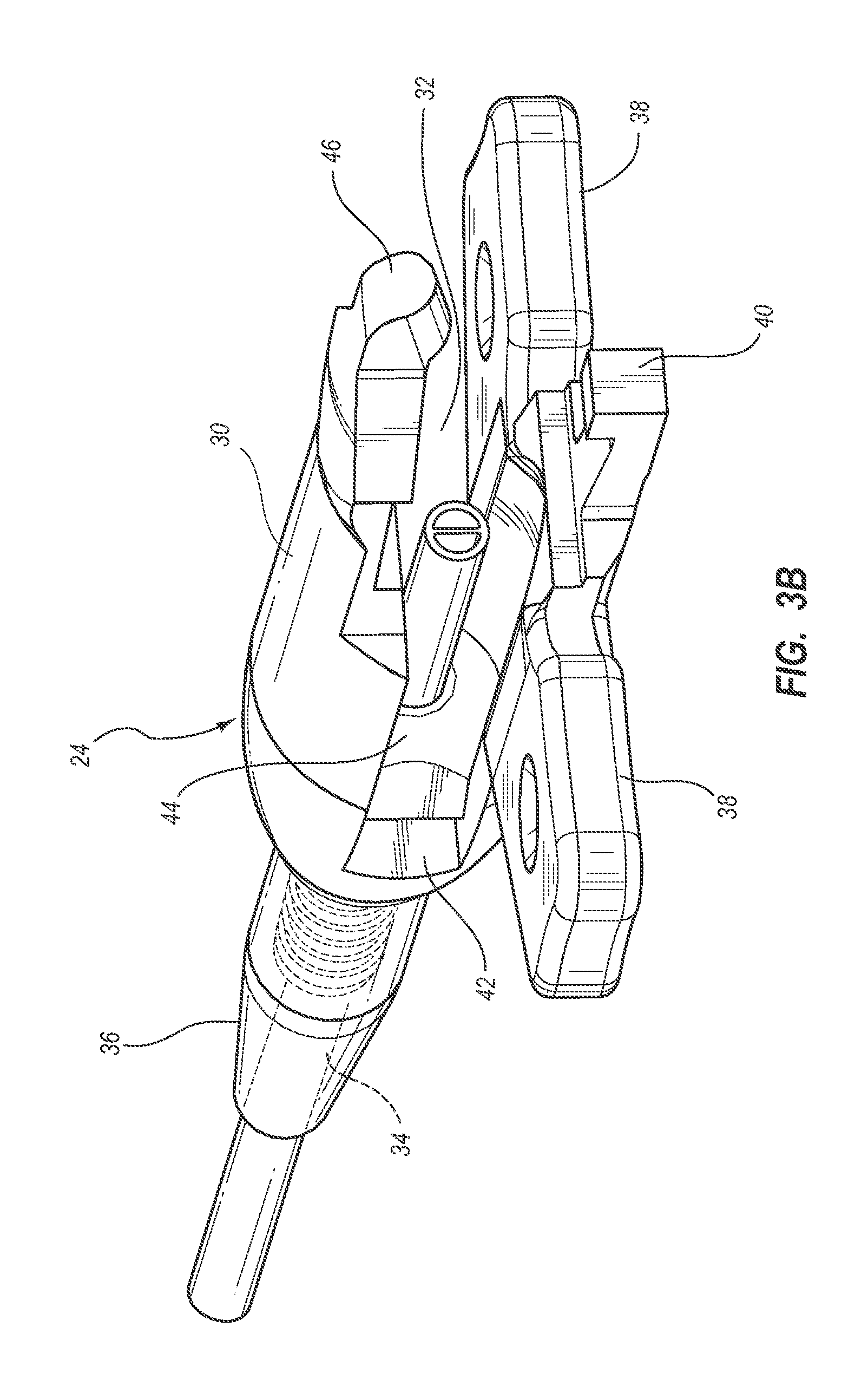
[0021] FIGS. 3A-3F show that in the present embodiment the distal hub portion 24 includes a body 30 defining a cavity 32 sized to inter-engage with the proximal hub portion 26. The body 30, together with a nose portion 36 thereof, further defines a conduit 34 through which extends a proximal portion of the catheter tube 12. Suture wings 38 for securing the hub 22 to the body of the patient 18 can also be included.
[0022] A connector latch 40 is included for enabling locking attachment of the distal hub portion 24 with the proximal hub portion 26 after placement of the hub 22 is complete, as will be described. Additionally, receptacles 42 are included on the body 30 of the distal hub portion 24 for engagement with corresponding latches 62 (FIG. 4A) included on the proximal hub portion 26. Of course, it is appreciated that the latches and receptacles described herein are merely one example for enabling attachment between the two hub portions 24 and 26; other attachment modes can also be employed without limitation. For example, the use of differing numbers of locking members, the use of differently shaped locking members, and the placement of the locking members in other locations on the distal hub portion are contemplated.
[0023] The distal hub portion 24 further includes an actuation surface 44, disposed adjacent the cavity 32 about a proximal opening of the conduit 34, which is configured to activate a compression element for sealing a fluid path of the catheter, as will be described further below. A tip portion 46 also proximally extends from the distal hub portion 24.
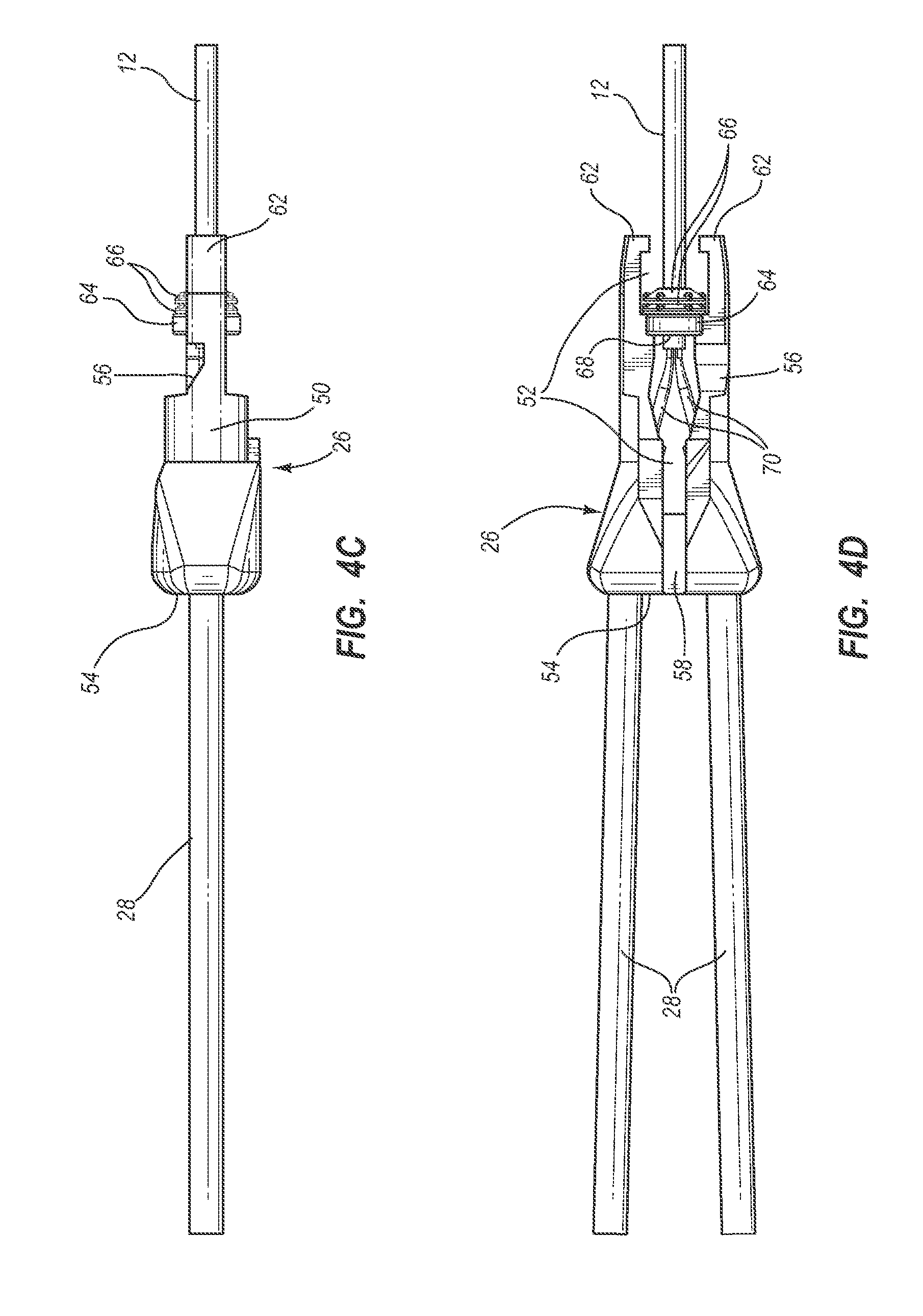
[0024] FIGS. 4A-4F depict various details of the proximal hub portion 26 of FIG. 2. As shown, the proximal hub portion 26 includes a body 50 that is sized to inter-engage with the proximal hub portion 26. The body 50 of the proximal hub portion 26 defines various features, including a cavity 52 a base surface 54 adjacent the points of entry for the extension legs 28 into the body, and a notch 56 in communication with the cavity. A notch 58 is also defined by the body 50 for receiving the tip portion 46 of the distal hub portion 24 (FIG. 3A) when the distal and proximal hub portions are mated together.
[0025] As best seen in FIG. 4E, the proximal hub portion 24 includes a latch receptacle 60 for receiving the connector latch 40 of the distal hub portion 24 when the hub portions are mated to one another. In addition, the proximal hub portion 26 includes two connector latches 62 configured to engage the receptacles 42 included on the distal hub portion 24, best seen in FIGS. 3A and 3B. As has been mentioned, the latches and receptacles described herein serve as one example of structures for lockingly mating the distal hub portion 24 to the proximal hub portion after positioning of the hub (described below) is complete.
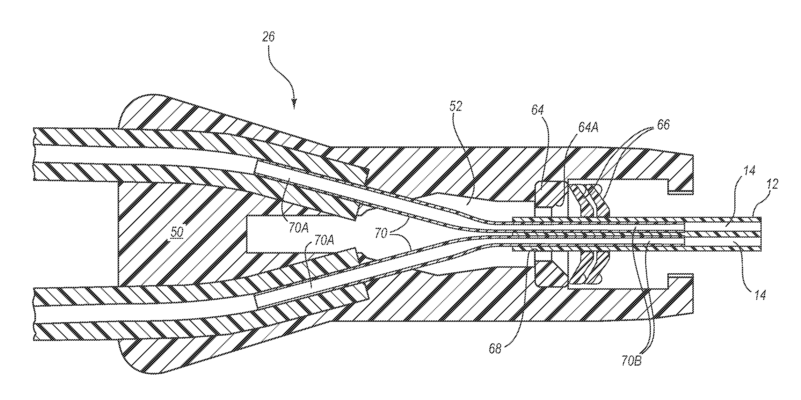
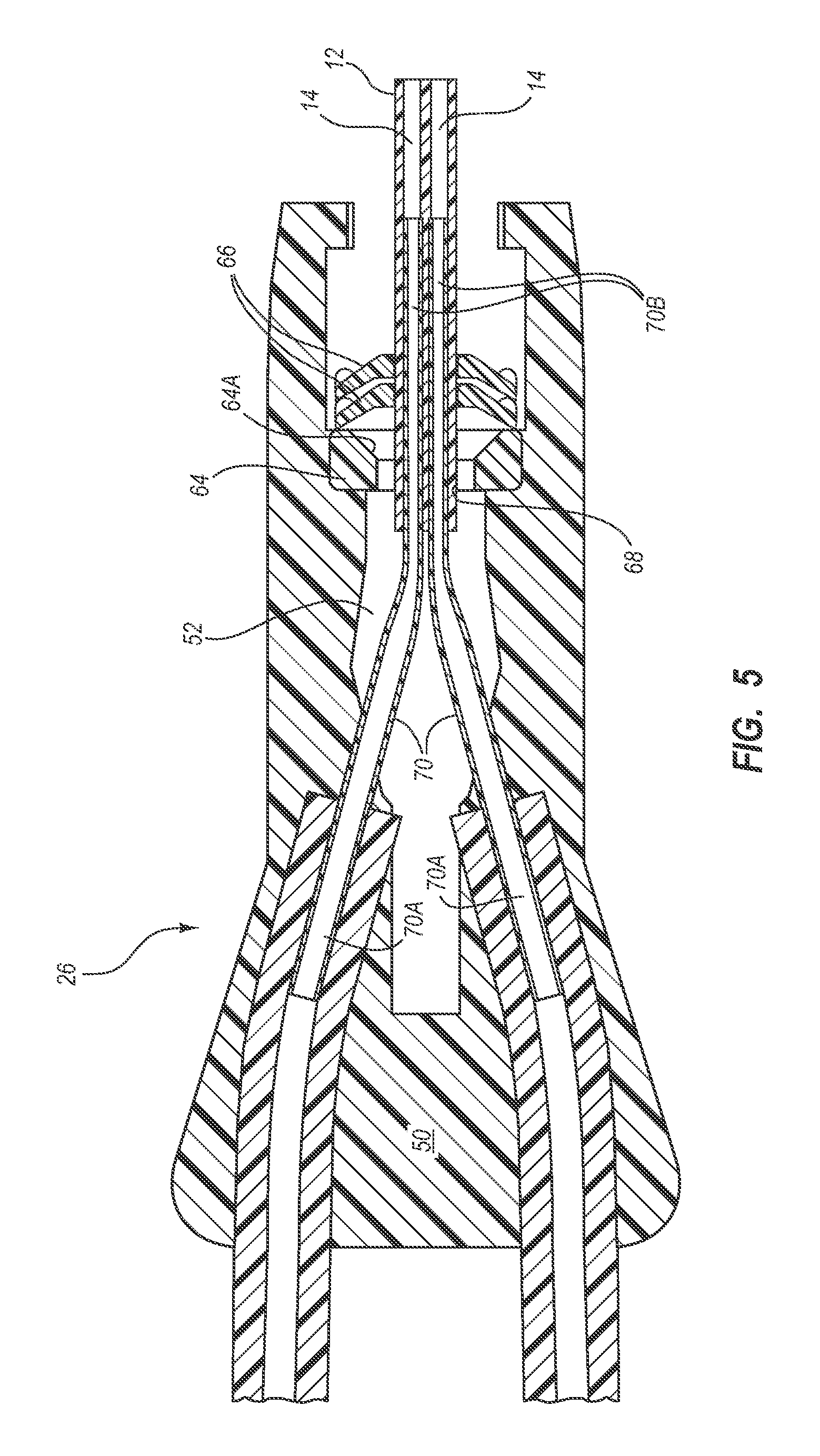
[0026] As seen in FIGS. 4A-4F, the proximal hub portion 26 includes an annular compression support member 64 disposed in the cavity 52, against which are positioned a plurality of annular compression washers 66. The compression support member 64 and compression washers 66 cooperate to define a conduit 68 through which a proximal portion of the catheter tube 12 extends. In addition, two tube pins 70 are included with the proximal hub portion 26 and each includes a proximal portion 70A and a distal portion 70B. As best seen in FIG. 5, the proximal portion 70A of each tube pin 70 is included within the hub portion body 50 so as to be in fluid communication with a respective one of the extension legs 28. The distal portion 70B of each tube pin 70 is disposed within a respective one of the lumens 14 of the catheter tube 12 via a proximal end 12A thereof. In this way, fluid communication is established between the extension legs 28 and the respective lumens 14 of the catheter tube 12. As will be seen, the compression washers 66 are employed when actuated to seal the interface between the tube pins and the catheter tube 12.
[0027] It is appreciated that that the number and type of components for sealing the tube pin/catheter tube interface can vary from what is shown and described herein; indeed, compression rings, collets, barbs, and other sealing components can be employed, for instance. In one embodiment, for instance, a silicone sleeve can be included to seal the tube pin/catheter interface, wherein the sleeve is radially constrained about its outer diameter, then compressed axially so that the inner diameter of the sleeve decreases to seal the interface. Further, note that the number of extension legs, tube pins, and catheter lumens can vary from the dual configurations shown and described herein. For instance, the catheter can include one, three, or more lumens, with a corresponding or different number of tube pins and extension legs.
[0028] FIGS. 6A and 6B show that in the present embodiment a first cutting member 80 is included to assist in placing the catheter 10. In particular, the first cutting member 80 extends through the notch 56 defined in the body 50 of the proximal hub portion 26 and is positioned to longitudinally slice along the catheter tube 12, cutting across each lumen 14 as the hub 22 is axially slid distally along the catheter tube toward the catheter insertion site 20 of the patient 18 (FIG. 1) during catheter placement procedures, described in greater detail below. Slicing of the catheter tube 12 in this manner enables the distal portion 70B of each tube pin 70 to remain in the uncut portion of its respective catheter tube lumen 14 distal to the first cutting member 80 as the hub is distally advanced along the catheter tube.
[0029] FIG. 6B shows that, as the hub 22 advances distally, the catheter tube 12 is cut by the first cutting member 80 and the two resulting pieces of the catheter tube extend proximally through the cavities 32, 52 of the hub portions 24, 26. The first cutting member 80 is shown positioned at a relatively small angle with respect to a longitudinal axis of the catheter tube 12 so as to assist with urging the upper cut portion of the catheter tube to exit the hub portion cavities 32, 52. The cut catheter pieces can be trimmed off after the hub 22 is slid into the desired position with respect to the catheter insertion site 20 of the patient 18. The first cutting member 80 can be included with a removable assembly tool that is temporarily attached to the hub 22, such as that shown in FIG. 8D for instance, or in one embodiment may be integrated into or removable from the hub itself. Thus, it is seen that the first cutting member 80 serves as one example of a means for cutting a proximal portion of the catheter tube; other structures or components can also acceptably accomplish the desired cutting.
[0030] FIG. 7A shows a cross sectional view of the catheter tube 12; FIG. 7B shows the catheter tube after cutting by the first cutting member 80 along a cut line 84 as described above. FIG. 7C shows the catheter tube 12 after cutting along the cut lines 84 by cutting members according to another embodiment, wherein two cutting members cut at opposing points along the outer wall of the catheter. In this example, the catheter tube 12 remains in one piece after cutting, as opposed to the two portions remaining after cutting as shown in FIG. 7B. These and other slicing scenarios are therefore contemplated. For instance, a triple lumen catheter tube can be sliced so as to result in a one, two, or three piece remaining portion after cutting.
[0031] FIG. 7C thus illustrates use of another example of a means for cutting a proximal portion of the catheter tube, according to one embodiment. As should therefore appreciated, the number, type, positioning, and other configuration of the means for cutting can vary as appreciated by one skilled in the art.
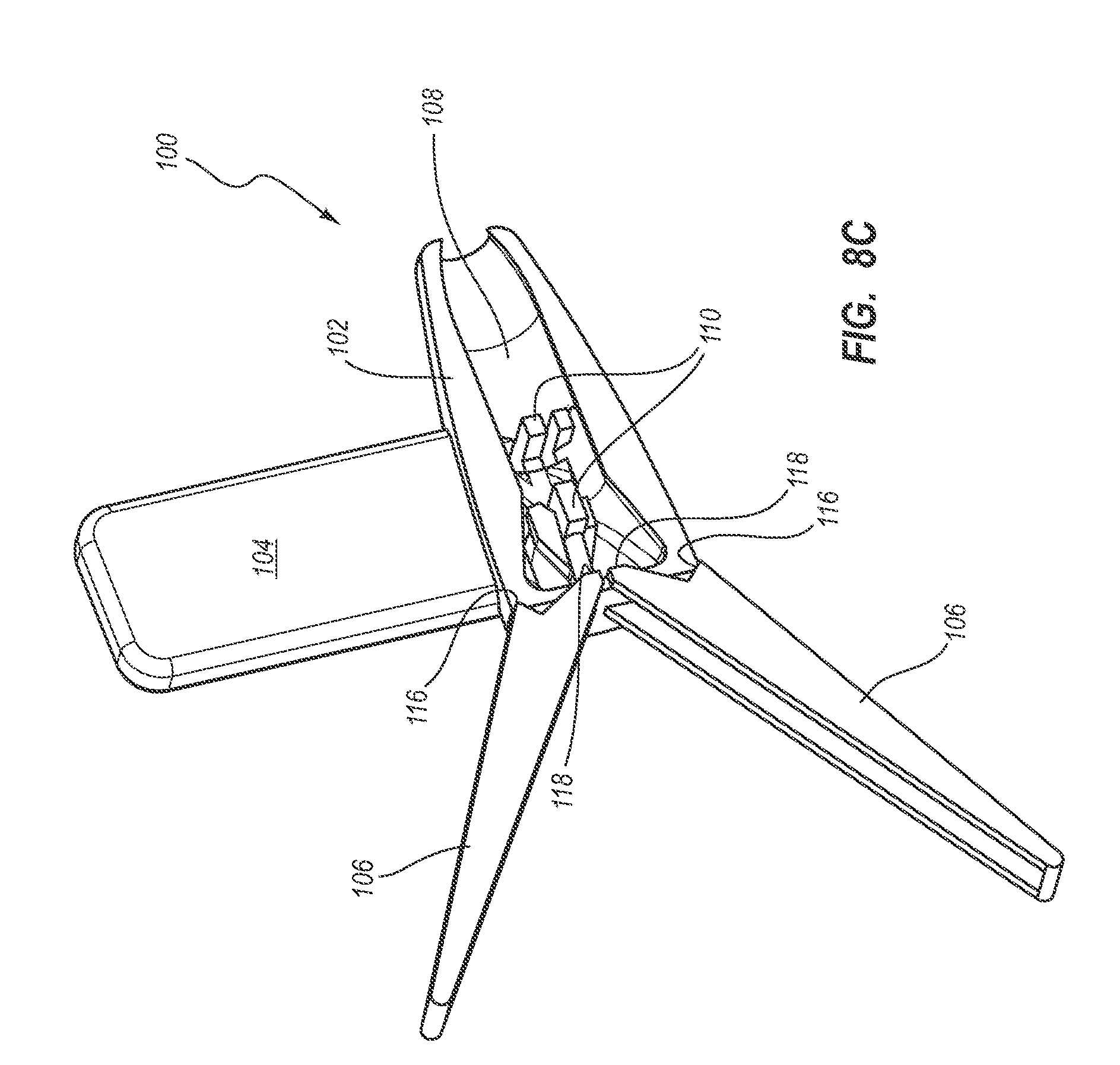
[0032] Reference is now made to FIGS. 8A-8E in describing an assembly tool 100 for assisting in the advancement and locking of the portions of the hub 22 during catheter placement into the body of the patient 18. The assembly tool 100 also maintains the two hub portions 24 and 26 in a state of suitable separation during advancement and positioning of the hub. As shown, the assembly tool 100 includes a main body 102, a cutting member housing 104, and one or more leverage components, here configured as two lever arms 106.
[0033] In greater detail, the main body 102 of the assembly tool 100 includes a shell-like structure that defines a cavity 108 sized to receive the two portions 24, 26 of the hub 22 in their engaged but unlocked state as shown in FIG. 2. As best seen in FIG. 8C, the main body 102 further defines various stabilization features 110 included within the cavity 108 to assist in securing the hub 22 in place while it is positioned within the cavity. In one embodiment, one or more stabilization features can be included on the cutting member housing as well.
[0034] The cutting member housing 104 is removably attached to the assembly tool main body 102. As mentioned further above, the cutting member housing 104 houses the first cutting member 80, as shown in FIG. 8D such that the first cutting member extends through the notch 56 in the proximal hub portion body 50 (FIG. 6A) when the proximal hub portion 26 is disposed within the assembly tool cavity 108. As mentioned, this enables the first cutting member 80 to cross sectionally slice the catheter tube 12 as it passes through the hub 22 during distal hub advancement along the catheter tube.
[0035] The cutting member housing 104 further includes a second cutting member 112 that is positioned such that a tip 112A thereof extends through the proximal hub portion body 50 and into the cavity 52, as shown in FIG. 8E. So positioned, and with the its cutting surface facing proximally, the tip 112A of the second cutting member 112 is employed to trim off the portions of the catheter tube 12 extending from the proximal hub portion cavity 52 (FIG. 6B) after the tube has been sliced by the first cutting member 80 during distal advancement of the hub 22 along the catheter tube. Further details regarding catheter tube trimming by the second cutting member 112 are given further below. Note that the main body 102 of the assembly tool 100 includes a window 114 to enable the sliced portions of the catheter tube 12 extending from the hub portion cavities 32, 52 to extend through the assembly tool (see, e.g., FIG. 9A).
[0036] The lever arms 106 of the assembly tool 100 are lever components employed to lockingly mate the distal hub portion 24 and the proximal hub portion 26 to each other after the hub 22 has been slid along the catheter tube 12 to a desired location. As best seen in FIGS. 8C and 8D, in the present embodiment each lever arm 106 includes a hinge point 116, at which point the lever arm is hingedly connected to the main body 102 of the assembly tool 100, and an engagement surface 118.
[0037] As will be described in further detail below, as the lever arms 106 are pinched squeezed together the engagement surface 118 of each lever arm pushes against the base surface 54 of the proximal hub portion 26. This causes the distal hub portion 24 to fully engage the proximal hub portion 26, in turn causing the connector latches 62 of the proximal hub portion to engage with the corresponding receptacles 42 of the distal hub portion 24 and the connector latch 40 thereof to engage with the receptacle 60 of the proximal hub portion, thus locking the two hub portions together. Locking of the distal and proximal hub portions 24, 26 also causes a compressive fit to be established between the tube pins 70 and the uncut proximal portion of the catheter tube 12, as will be details further below. As mentioned, it is appreciated that other levered and non-levered structures can be employed for causing the mating of the two hub portions as described herein; as such, the present discussion should not be considered limiting.
[0038] Reference is now made to FIGS. 9A-9D in describing placement and locking of the hub 22 about the catheter tube 12 of the catheter 10 as part of a procedure for placing the catheter within the body of the patient 18 (FIG. 1), according to one embodiment. Note again that the hub, assembly tool, and method described herein can be adapted for use with other catheters and tubular medical devices for placement within a patient.
[0039] The catheter 10 can be configured before placement with the catheter hub 22 generally positioned with respect to the catheter tube 12 as shown in FIG. 9A and with the assembly tool 100 disposed about the hub so as to maintain the distal and proximal hub portions 24, 26 in a desired state of proximate separation as shown in FIG. 2. A distal portion of the catheter tube 12 is inserted into the patient via the insertion site 20. The hub 22 and/or assembly tool 100 is then grasped and slid distally along the catheter tube 12 toward the insertion site 20, as indicated by the arrow in FIG. 9B (note that any stylet or guidewire included in one or both of the catheter tube lumens 14 is first removed before hub advancement). This causes portions of the catheter tube 12 to pass through the conduits 34 and 68 defined in the distal hub portion 24 and proximal hub portion 26, respectively (FIGS. 3A, 3C, 5), and past the first cutting member 80 (FIGS. 6A, 6B), which extends into the hub portion cavities 32, 52 from the cutting member housing 104 (FIG. 8D).
[0040] Passage of the catheter tube 12 past the first cutting member 80 causes cutting and splitting of the catheter tube into two pieces, thus enabling distal portions 70B of the tube pins 70 to remain within the uncut portion of the catheter tube lumens 14 (FIGS. 5-6B) while the hub 22/assembly tool 100 is distally advanced. The split pieces of the catheter tube 12 exit the hub portion cavities 32, 52 and out through the assembly tool window 114 (FIG. 9B). Note that the distal movement of the hub 22 along the catheter tube 12 toward the catheter insertion site 20 results in the split tube advancing out the assembly tool window 114.
[0041] As shown in FIG. 9C, once the hub 22/assembly tool 100 has been advanced to a desired position with respect to the insertion site 20, the split catheter tube 12 extending from the proximal hub portion cavity 52 via the assembly tool window 114 is pulled as indicated by the arrow disposed on the assembly tool main body 102 such that a portion of the split catheter tube proximate the tip 112A of the second cutting member 112 (FIG. 8E) is cut by the cutting member tip, thus separating it from the catheter 10 and enabling it to be discarded.
[0042] With the first and second cutting members 80, 112 no longer needed, the cutting member housing 104 can then be removed from the assembly tool 100 (FIG. 9C), which removes both cutting members from the hub 22 and assembly tool. The cutting member housing can be disposed of. In one embodiment, a blade safety mechanism can be included to protect the user from the cutting members 80, 112 when the cutting member housing 104 is removed. Note that in one embodiment, the cutting member housing can include only one of the two cutting members. In another embodiment, one or both of the cutting members can be removably or permanently integrated into one of the hub portions itself, or the cutting members can be combined into a single component. In yet another embodiment, no assembly tool is included with the hub.
[0043] Finally, the lever arms 106 are actuated by pinching them together, as shown in FIG. 9C, in order to lockingly mate the distal and proximal hub portions 24, 26 together, as has been described. Mating of the hub portions 24, 26 in this manner further causes actuation of the compression washers 66. In particular, mating of the distal and proximal hub portions 24, 26 causes the invertible compression washers 66 to become compressed between the actuation surface 44 of the distal hub portion (FIG. 3C) and the compression support member 64 (FIG. 4E). This compression causes the actuation surface 44 to engage the most proximate compression washer and cause it and the other washers to invert, or fold in on themselves. This reduces the inner diameter of each compression washer 66, which in turn compresses the catheter tube 12 passing through the inner diameter against the distal portion 70B of the tube pins 70 disposed within the catheter tube lumens 14, thus fluidly sealing the tube pins within the catheter tube lumens and preventing fluid leakage from the interface. Note that a distal surface of the compression support member 64 includes a chamfered surface 64A that substantially matches the shape of the most proximal compression washer 66 after inversion thereof, as best seen in FIG. 5.
[0044] Thus it is seen that the compression washers serve as one example of a means for fluidly sealing a tube pin within a catheter lumen. It is appreciated, however, that other means can also be employed to accomplish the desired functionality as appreciated by one skilled in the art. For example, compression rings or collets of varying configurations can be employed in one embodiment. Note also that, though locking of the hub portions and compression of the tube pin/catheter lumen interface occurs in a single stage, in other embodiments these actions can occur separately in sequence. Note further that, in one embodiment, the distal and proximal hub portions can be locked together manually, i.e., without mechanical tool assistance, that the hub can include more than two portions, or that the hub can include a single piece that does not require locking together.
[0045] Once the hub 22 has been positioned and locked into place on the catheter tube 12, the assembly tool 100 can be removed from the hub, resulting in the catheter 10 configured as shown in FIG. 9D, including connectors 120 for connecting the catheter to suitable apparatus.
[0046] While certain representative embodiments and details have been shown for purposes of illustrating aspects contemplated by the instant disclosure, it will be apparent to those skilled in the art that various changes in the methods and apparatus disclosed herein may be made without departing from the scope contemplated by the instant disclosure, which is defined in the appended claims.
* * * * *
D00000
D00001
D00002
D00003
D00004
D00005
D00006
D00007
D00008
D00009
D00010
D00011
D00012

D00013

D00014

D00015

D00016

D00017
D00018

D00019

D00020

D00021

D00022

D00023

XML
uspto.report is an independent third-party trademark research tool that is not affiliated, endorsed, or sponsored by the United States Patent and Trademark Office (USPTO) or any other governmental organization. The information provided by uspto.report is based on publicly available data at the time of writing and is intended for informational purposes only.
While we strive to provide accurate and up-to-date information, we do not guarantee the accuracy, completeness, reliability, or suitability of the information displayed on this site. The use of this site is at your own risk. Any reliance you place on such information is therefore strictly at your own risk.
All official trademark data, including owner information, should be verified by visiting the official USPTO website at www.uspto.gov. This site is not intended to replace professional legal advice and should not be used as a substitute for consulting with a legal professional who is knowledgeable about trademark law.