Transducer Driver For Measuring A Parameter Of The Muscularskeletal System
Stein; Marc ; et al.
U.S. patent application number 12/826109 was filed with the patent office on 2010-12-30 for transducer driver for measuring a parameter of the muscularskeletal system. This patent application is currently assigned to OrthoSensor. Invention is credited to Andrew Kelly, Marc Stein.
| Application Number | 20100331685 12/826109 |
| Document ID | / |
| Family ID | 43379281 |
| Filed Date | 2010-12-30 |
| United States Patent Application | 20100331685 |
| Kind Code | A1 |
| Stein; Marc ; et al. | December 30, 2010 |
TRANSDUCER DRIVER FOR MEASURING A PARAMETER OF THE MUSCULARSKELETAL SYSTEM
Abstract
A measurement system for capturing a transit time, phase, or frequency of energy waves propagating through a propagation medium is disclosed. The measurement system comprises two different closed-loop feedback paths. The first path includes a transducer driver (726), a transducer (704), a propagation structure (702), a transducer (706), and a zero-crossing receiver (740). The transducer driver (726) efficiently drives the transducer (704) and comprises a digital driver (106), a level shifter (112), and a matching network (114). A second path includes a transducer driver (1126), a transducer (1104), a propagation medium (1102), a reflecting surface (1106), and an edge-detect receiver (1140). Energy waves in the propagating medium (1102) are reflected at least once. The edge-detect receiver (1140) detects a wave front of an energy wave. Each positive closed-loop path maintains the emission, propagation, and detection of energy waves in the propagation medium.
| Inventors: | Stein; Marc; (Chandler, AZ) ; Kelly; Andrew; (Scottsdale, AZ) |
| Correspondence Address: |
    Orthosensor, Inc.
    1560 Sawgrass Corporate Pkwy, 4th Floor
    Sunrise
    FL
    33323
    US
|
| Assignee: | OrthoSensor Sunrise FL |
| Family ID: | 43379281 |
| Appl. No.: | 12/826109 |
| Filed: | June 29, 2010 |
Related U.S. Patent Documents
| Application Number | Filing Date | Patent Number | ||
|---|---|---|---|---|
| 61221916 | Jun 30, 2009 | |||
| 61221761 | Jun 30, 2009 | |||
| 61221767 | Jun 30, 2009 | |||
| 61221779 | Jun 30, 2009 | |||
| 61221788 | Jun 30, 2009 | |||
| 61221793 | Jun 30, 2009 | |||
| 61221801 | Jun 30, 2009 | |||
| 61221808 | Jun 30, 2009 | |||
| 61221817 | Jun 30, 2009 | |||
| 61221867 | Jun 30, 2009 | |||
| 61221874 | Jun 30, 2009 | |||
| 61221879 | Jun 30, 2009 | |||
| 61221881 | Jun 30, 2009 | |||
| 61221886 | Jun 30, 2009 | |||
| 61221889 | Jun 30, 2009 | |||
| 61221894 | Jun 30, 2009 | |||
| 61221901 | Jun 30, 2009 | |||
| 61221909 | Jun 30, 2009 | |||
| 61221923 | Jun 30, 2009 | |||
| 61221929 | Jun 30, 2009 | |||
| Current U.S. Class: | 600/438 |
| Current CPC Class: | A61B 8/15 20130101; A61B 5/6878 20130101; A61B 5/7239 20130101; A61B 5/6846 20130101; A61B 5/4528 20130101; A61B 5/4509 20130101 |
| Class at Publication: | 600/438 |
| International Class: | A61B 8/00 20060101 A61B008/00 |
Claims
1. A transducer driver circuit in a positive closed-loop path that generates time and frequency specific energy waves and pulses to measure a parameter of the muscular-skeletal system.
2. The driver circuit of claim 1 further comprising a level shifter to raise or lower voltage levels of output pulses to voltage levels required to efficiently drive an energy emitting resonator or transducer given the characteristics of the resonator or transducer.
3. The driver circuit of claim 2 further comprising an impedance matching network to translate a digital output pulse into a required wave shape for efficiently and compactly driving the transducer.
4. The driver circuit of claim 3 further comprising control logic to generate drive signals according to the transducer characteristics and operational modes to achieve highly accurate control, timing, and duration of the generated energy waves and pulses.
5. The driver circuit of claim 4 where the driver circuit drives more than one transducer.
6. The driver circuit of claim 4 where the impedance matching network comprises a pi network.
7. The driver circuit of claim 4 where the driver circuit controls a duration of stimulation of the transducer.
8. The driver circuit of claim 4 further including a sensor in the positive closed-loop comprising: a first transducer; a propagation medium where the first transducer is coupled to the propagation medium at a first location; and a second transducer coupled to the propagation medium at a second location where the propagation medium is affected by the parameter of the muscular-skeletal system being measured and where there is a known relationship between the parameter being measured and one of transit time, phase, and frequency of energy waves propagating through the medium.
9. The driver circuit of claim 4 further including a sensor in the positive closed-loop comprising: a transducer; a propagation medium where the transducer is coupled to the propagation medium at a first location; and a reflecting surface coupled to the propagation medium at a second location where the propagation medium is affected by the parameter of the muscular-skeletal system being measured and where there is a known relationship between the parameter being measured and one of transit time, phase, and frequency of energy waves propagating through the medium.
10. The driver circuit of claim 1 where the transducer driver circuit maintains positive closed loop feedback operating in at least one of continuous wave mode, pulse-loop mode, and pulse echo-mode.
11. A sensor comprising: a first transducer; a propagation medium where the first transducer is coupled to the propagation medium at a first location; and a second transducer coupled to the propagation medium at a second location where the series and parallel resonance of the first transducer does not overlap the series and parallel resonance of the second transducer.
12. The sensor of claim 11 where the series and parallel resonance of the first transducer is less than the series and parallel resonance of the second transducer.
13. The sensor of claim 11 where the series and parallel resonance of the first transducer is greater than the series and parallel resonance of the second transducer.
14. The sensor of claim 11 where the propagation medium is a compressible waveguide to contain, propagate, and direct energy waves.
15. The sensor of claim 11 where the first transducer emits ultrasonic energy waves into the propagation medium at the first location.
16. A sensor system comprising: a transducer driver coupled in positive closed-loop feedback comprising: a digital driver having an input and an output; a level shifter having an input coupled to the input of the digital driver and an output; and a matching network having an input coupled to an output of the level shifter and an output.
17. The sensor system of claim 16 further including: a sensor in the positive closed-loop feedback comprising; a transducer having a terminal coupled to the output of the matching network; and a compressible propagation medium where the transducer couples to the medium at a first location and where the transducer is enabled to emit ultrasonic energy waves into the propagation medium.
18. The sensor system of claim 17 further including a reflecting surface at a second location of the propagation medium.
19. The sensor system of claim 17 further including a second transducer coupled to a second location of the propagation medium where the second transducer includes a terminal coupled to the input of the digital driver.
20. The sensor system of claim 17 further including: a control logic circuit having an input and an output coupled to the input of the digital driver; and an amplifier having an input coupled to the output of the level shifter and an output coupled to the input of the matching network where the sensor system measures one of transit time, phase, and frequency of the ultrasonic energy waves propagating through the propagation medium.
Description
CROSS-REFERENCE TO RELATED APPLICATIONS
[0001] This application claims the priority benefit of U.S. provisional patent applications Nos. 61/221,761, 61/221,767, 61/221,779, 61/221,788, 61/221,793, 61/221,801, 61/221,808, 61/221,817, 61/221,867, 61/221,874, 61/221,879, 61/221,881, 61/221,886, 61/221,889, 61/221,894, 61/221,901, 61/221,909, 61/221,916, 61/221,923, and 61/221,929 all filed 30 Jun. 2009; the disclosures of which are hereby incorporated herein by reference in their entirety.
FIELD
[0002] The present invention pertains generally to measurement of physical parameters, and particularly to, but not exclusively, to control and driver circuitry for generating energy waves or pulses.
BACKGROUND
[0003] Sensors are used to provide information to a device or system. The sensor information can be critical to device operation or provide additional data on the system or an external environment. For example, a temperature sensor is commonly used to monitor the operating temperature of components. The temperature sensor can be used to monitor average operating temperatures and instantaneous operating extremes. Sensor data can be used to understand how device functions or performs in different working environments, users, and environmental factors. Sensors can trigger an action such as turning off the system or modifying operation of the system in response to a measured parameter.
[0004] In general, cost typically increases with the measurement precision of the sensor. Cost can limit the use of highly accurate sensors in price sensitive applications. Furthermore, there is substantial need for low power sensing that can be used in systems that are battery operated. Ideally, the sensing technology used in low-power applications will not greatly affect battery life. Moreover, a high percentage of battery-operated devices are portable devices comprising a small volume and low weight. Device portability can place further size and weight constraints on the sensor technology used. Thus, form factor, power dissipation, cost, and measurement accuracy are important criteria that are evaluated when selecting a sensor for a specific application.
BRIEF DESCRIPTION OF THE DRAWINGS
[0005] Various features of the system are set forth with particularity in the appended claims. The embodiments herein, can be understood by reference to the following description, taken in conjunction with the accompanying drawings, in which:
[0006] FIG. 1 is a block diagram of a transducer driver in accordance with one embodiment;
[0007] FIG. 2 is a block diagram of the integrated transducer driver coupled to drive a transducer of a sensing assembly in accordance with one embodiment;
[0008] FIG. 3 is an exemplary propagation tuned oscillator (PTO) incorporating the integrated transducer driver to maintain positive closed-loop feedback in accordance with one embodiment;
[0009] FIG. 4 is a set of graphs of frequency characteristics of a transducer driven by the integrated transducer driver for non-optimized and optimized configurations in accordance with one embodiment;
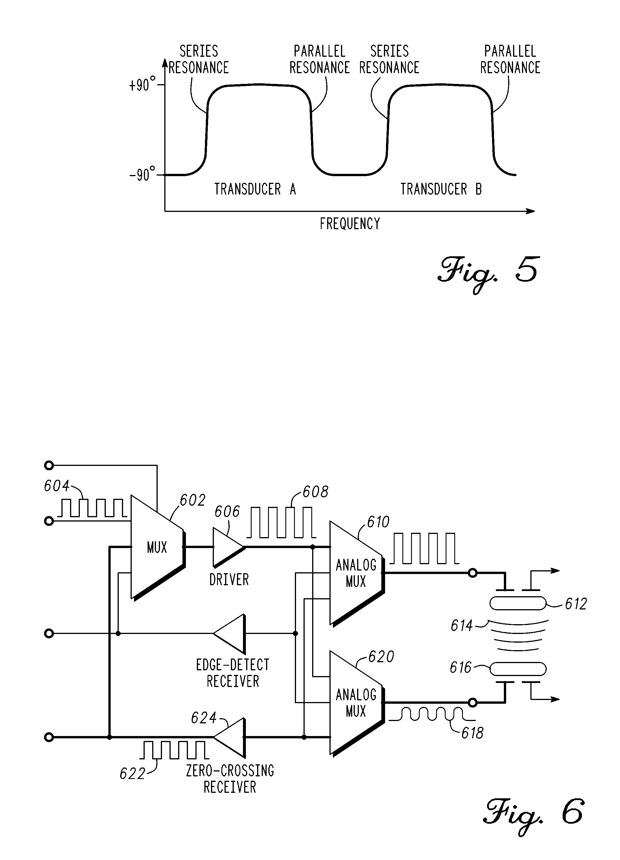
[0010] FIG. 5 is an illustration of a plot of non-overlapping resonant frequencies of paired transducers in accordance with an exemplary embodiment;
[0011] FIG. 6 is a sensor interface diagram incorporating the transducer driver in a continuous wave multiplexing arrangement for maintaining positive closed-loop feedback in accordance with one embodiment;
[0012] FIG. 7 is an exemplary block diagram of a propagation tuned oscillator (PTO) incorporating the transducer driver for operation in continuous wave mode;
[0013] FIG. 8 is a sensor interface diagram incorporating the transducer driver in a pulse multiplexing arrangement for maintaining positive closed-loop feedback in accordance with one embodiment;
[0014] FIG. 9 is an exemplary block diagram of a propagation tuned oscillator (PTO) incorporating the transducer driver for operation in pulse mode in accordance with one embodiment;
[0015] FIG. 10 is a sensor interface diagram incorporating the transducer driver in a pulse-echo multiplexing arrangement for maintaining positive closed-loop feedback in accordance with one embodiment;
[0016] FIG. 11 is an exemplary block diagram of a propagation tuned oscillator (PTO) incorporating the transducer driver for operation in pulse echo mode;
[0017] FIG. 12 is an illustration of a sensor placed in contact between a femur and a tibia for measuring a parameter in accordance with an exemplary embodiment.
DETAILED DESCRIPTION
[0018] Embodiments of the invention are broadly directed to measurement of physical parameters, and more particularly, to control and driver circuitry for generating energy waves or pulses.
[0019] The following description of exemplary embodiment(s) is merely illustrative in nature and is in no way intended to limit the invention, its application, or uses.
[0020] Processes, techniques, apparatus, and materials as known by one of ordinary skill in the art may not be discussed in detail but are intended to be part of the enabling description where appropriate. For example specific computer code may not be listed for achieving each of the steps discussed, however one of ordinary skill would be able, without undo experimentation, to write such code given the enabling disclosure herein. Such code is intended to fall within the scope of at least one exemplary embodiment.
[0021] Additionally, the sizes of structures used in exemplary embodiments are not limited by any discussion herein (e.g., the sizes of structures can be macro (centimeter, meter, and larger sizes), micro (micrometer), and nanometer size and smaller).
[0022] Notice that similar reference numerals and letters refer to similar items in the following figures, and thus once an item is defined in one figure, it may not be discussed or further defined in the following figures.
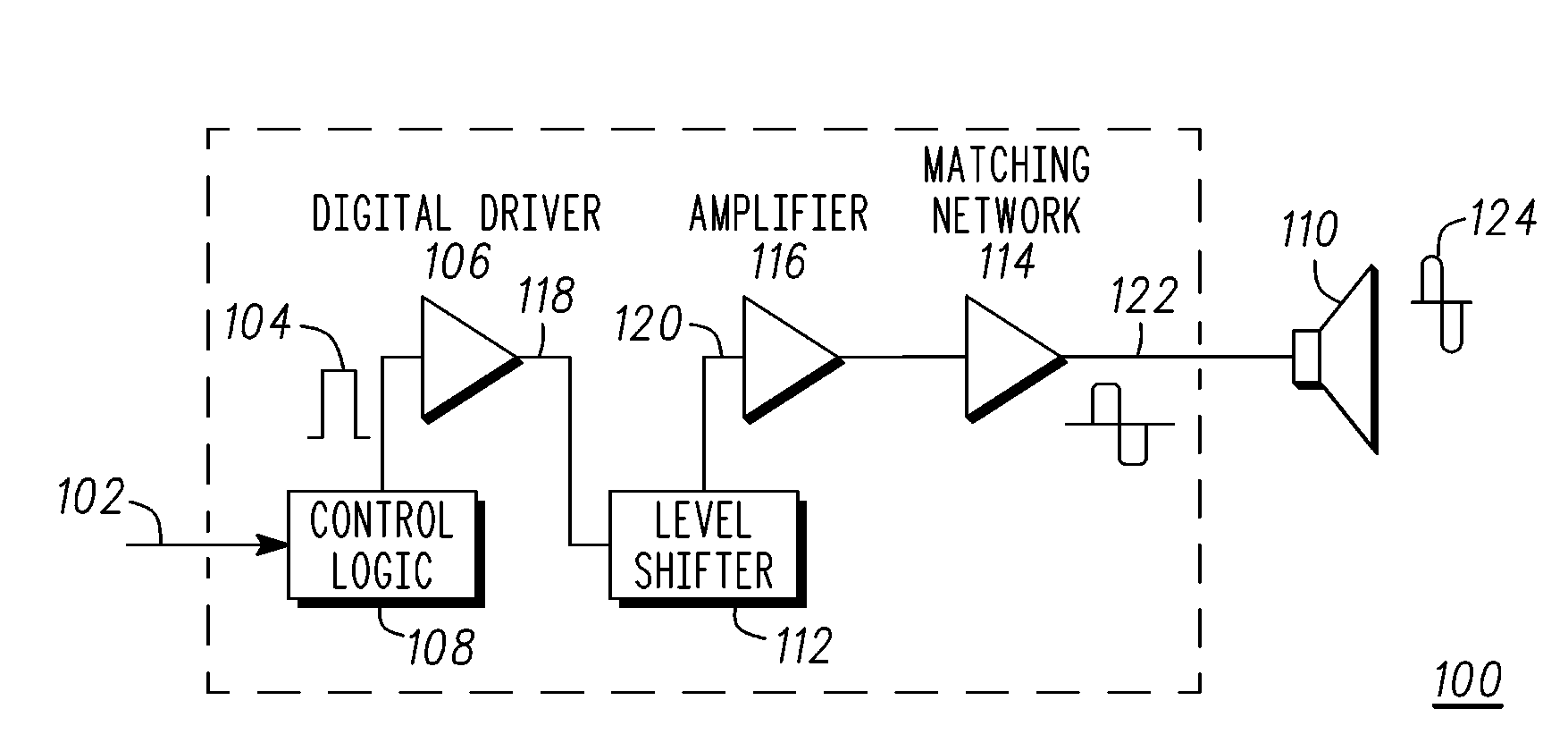
[0023] FIG. 1 illustrates a low power consumption integrated transducer driver circuit 100 in accordance with an exemplary embodiment. In a first embodiment, driver circuit 100 efficiently drives a transducer to generate time and frequency specific energy waves and pulses. It includes digital logic to generate drive signals according to the transducer characteristics and operational modes to achieve highly accurate control, timing, and duration of the generated energy waves and pulses. In one arrangement, the output driver is coupled to an ultrasonic sensing assembly to efficiently generate continuous ultrasonic waves or ultrasonic pulses that propagate through a propagation medium. The driver circuit includes a level shifter 112 to raise or lower voltage levels of output pulses to voltage levels required to efficiently drive an energy emitting resonator or transducer given the characteristics of the resonator or transducer, the frequency and duration of the output waves, and the shape of the output pulse. It includes an impedance matching network 114 to translate the digital output pulse into a required wave shape for efficiently and compactly driving the transducer. This configuration provides the benefit for battery or temporarily powered sensing systems to drive the energy emitting resonators or transducers with much less power consumption than a Digital to Analog Converter (DAC) based design.
[0024] In a second embodiment, the driver circuit 100 is incorporated within a propagation tuned oscillator (PTO) to maintain positive closed-loop feedback. The PTO can operate in continuous wave mode, pulse-loop mode, pulse-echo mode, or controlled combination thereof. The driver circuit 100 is electrically integrated with the PTO by multiplexing input and output circuitry, including off-board components of an impedance matching network, to achieve ultra low-power and small compact size. In this arrangement, off-board energy emitting resonators or transducers are operated at optimum frequencies and drive voltages and currents to achieve optimal performance at a minimum level of power consumption. The drive circuit 100 can singly drive multiple energy emitting resonators or transducers to achieve this level of performance; that is, only one driver circuit can be shared. Appropriate duty cycles and multiplexing timing for optimum frequencies of the energy emitting resonators or transducers are selected to conserve both power and space without compromising performance. This enables, but is not limited to, the design and construction of compact measurement modules or devices with thickness on the order of a few millimeters.
[0025] In one embodiment, low power consumption transducer driver circuit 100 comprises control logic 108, a digital driver 106, level shifter 112, an amplifier 116, and matching network 114. The driver circuit 100 can be implemented in discrete analog components, digital components, an application integrated circuit, or a combination thereof. In a low power application, transducer driver circuit 100 is integrated with other circuitry of the propagation tuned oscillator. Briefly, the transducer driver circuit 100 accurately controls emissions of energy waves or pulses, and parameters thereof, including, but not limited to, transit time, phase, or frequency of the energy waves or pulses. A brief description of the method of operation is as follows.
[0026] An input 102 receives a signal to emit an energy wave. Input 102 couples to control logic 108. Control logic 108 controls the timing and frequency of stimulation of an energy transducer 110. A digital pulse 104 from digital control logic 108 is provided to an input of driver 106. In an energy pulse mode, digital control logic 108 also controls the duration of the stimulation. One or more pulses from an output 118 of driver 106 is coupled to level shifting circuitry 112. Level shifting circuitry 112 adjusts the output voltage of driver 106 to efficiently drive energy transducer 110. One or more level shifted pulses are provided at an output 120 of level shifter 112 to amplifier 116. Amplifier 116 amplifies the signal at output 120 which is provided to an input of matching network 114. Matching network 114 matches the electrical characteristics of the energy transducer 110. Output signal 122 from the matching network 114 drive energy transducer 110. Matching network 114 converts the output pulse from amplifier 116 to the required wave shape, frequency and phase. Energy waves 124 are emitted by energy transducer 110 into the medium.
[0027] As discussed above, the electronic components are operatively coupled together as blocks of integrated circuits. As will be shown ahead, this integrated arrangement performs its specific functions efficiently with a minimum number of components. This is because the circuit components are partitioned between structures within an integrated circuit and discrete components, as well as innovative partitioning of analog and digital functions, to achieve the required performance with a minimum number of components and minimum power consumption.
[0028] Briefly, an input of digital driver 106 is driven by digital control logic 108, which ultimately controls the timing and frequency of the resulting output signal 122. As will be shown ahead, the output signal 122 drives an energy transducer 110 to output an energy wave or energy pulse. The drive circuit 100 is optimally configured to generate the output signal 122 according to the transducer characteristics (e.g., frequency, stiffness, Q, ringing, inductance, ringing, decay, feedback) and in certain cases the operating mode (e.g., continuous, pulse-loop, and pulse echo). For example, in pulse-loop mode, digital control logic 108 also controls the duration of the transducer 110 stimulation. Level shifter 112 adjusts the output voltage of driver output 106 to efficiently drive energy transducer 110. More specifically, the level shifter 112 raises or lowers voltage levels of output pulses to the voltages required to efficiently drive the energy emitting resonator or transducer 110 given the characteristics of the resonator or transducer 110, the frequency and duration of the output waves, and the shape of the output pulse. Matching network 114 matches the electrical characteristics of the energy transducer 110 and converts the output pulse 122 to the required wave shape, frequency and phase. The generated digital output waveform 122 or pulse may have a moderately sharp leading edge.
[0029] With regard to the integrated transducer driver 100, efficient use of power and conservation of charge is required for ultra low power operation. Energy emitting resonators or transducers 110 can be stimulated with a sine wave or other form of continuous wave to efficiently emit energy waves of the required frequency, phase, and duration. Partitioning circuit components between structures within the integrated circuit and discrete components enhances design flexibility and minimize power consumption without compromising performance. Therefore, the driver circuit 100 and matched network 114 together efficiently convert the input pulse 104 to an energy wave 124 of the required frequency, phase, and duration; which is, specific to operation of transducer 110.
[0030] The output of the driver amplifier 116 is coupled with the impedance matching network 114, such as, but not limited to, a pi network. This pi network can include a discrete inductor or inductors and a discrete capacitor or capacitors to translate the digital output pulse into the required wave shape efficiently and compactly. In one arrangement, the phase and time delay through the pi network are constant. The pi network may also include resistance as well as the discrete inductance and capacitance components. The resistance element is primarily parasitic resistances within the integrated components and interconnects and is included in the analysis and design of the pi network to assure matching the electrical drive requirements of the energy emitting device.
[0031] Driving the energy emitting transducer 110 through the impedance matching network 114 achieves a waveform 122 that is input to the energy emitting resonator or transducer 110. This drives the energy emitting resonators or transducers 110 efficiently and with much less power consumption than a Digital to Analog Converter (DAC) based design. The integration of miniature, surface mountable, inductors and capacitors enables highly compact driver circuit and minimizes the total number of electronic components. In a hybrid approach, off-chip and return to on-chip, may have size penalty but can be integrated to save power and reduce design complexity.
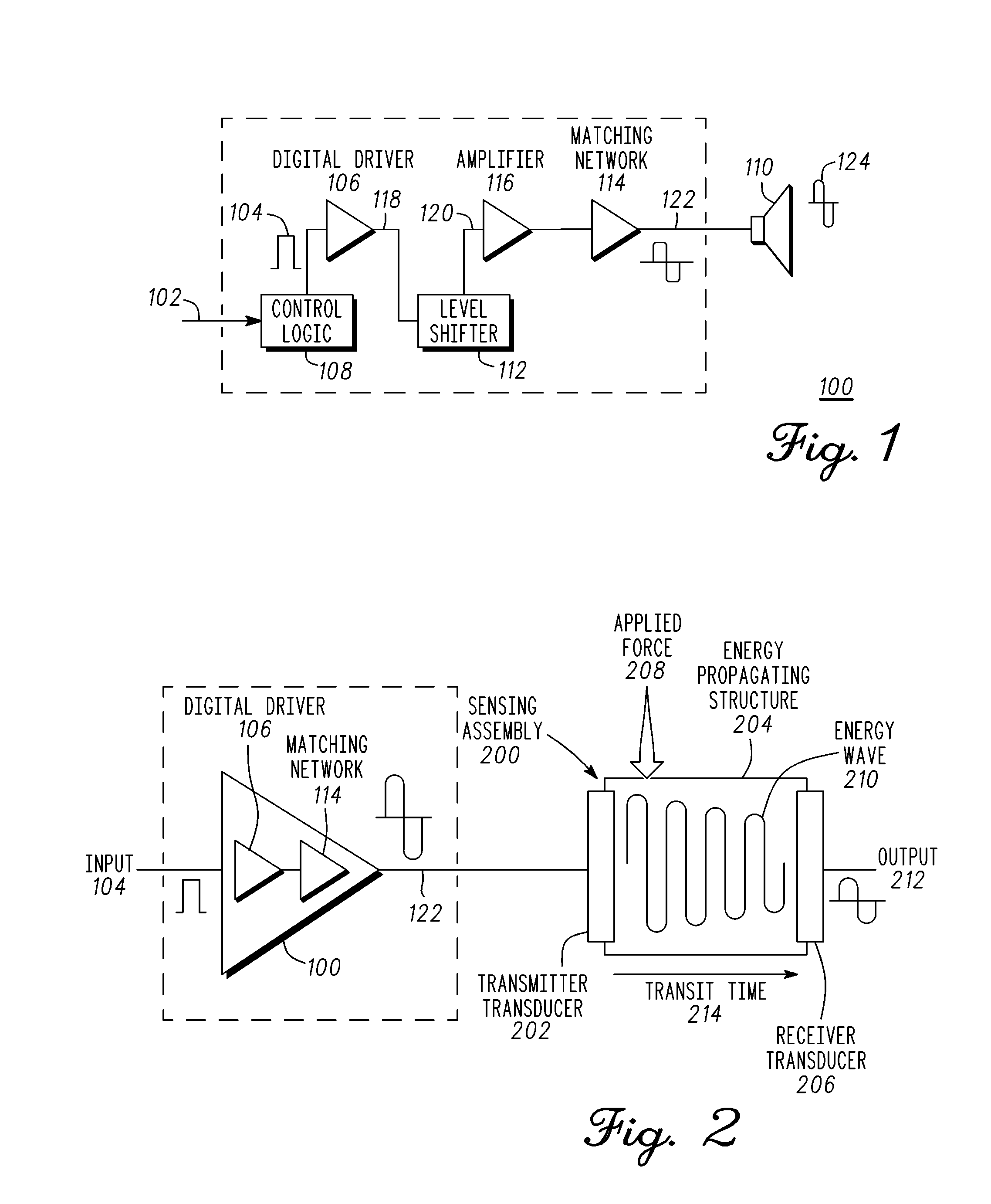
[0032] FIG. 2 illustrates a block diagram of the transducer driver circuit 100 coupled to a sensing assembly 200 in accordance with an exemplary embodiment. The sensing assembly 200 comprises a transmitter transducer 202, an energy propagating medium 204, and a receiver transducer 206. Alternatively, the sensing assembly can comprise a single transducer, a propagating medium, and a reflecting surface. Energy waves or pulses are emitted by the single transducer into the medium, propagate in the medium, are reflected by the reflecting surface, and the reflected energy wave received by the single transducer. This provides the benefit of lower cost due to the use of the single transducer. As will be explained ahead in further detail, the sensing assembly 200 in one embodiment is part of a sensory device that assesses loading, in particular, the externally applied forces 208 on the sensing assembly 200. In one embodiment, forces 208 are applied in a direction corresponding to energy wave propagation in the propagating structure or medium 204 such that propagating structure 204 is changed dimensionally. The transducer driver circuit 100 drives the transmitter transducer 202 of the sensing assembly 200 to produce energy waves 210 that are directed into the energy propagating medium 204. The time for an energy wave to propagate from transducer 202 to transducer 206 is a transit time 214. Changes in the energy propagating medium 204 due to the externally applied forces 208 change the frequency, phase, and transit time of energy waves 210. A controller (not shown), as will be explained below, operatively coupled to the receiver transducer 206 monitors an output signal 212 for these characteristic changes to assess parameters of interest (e.g., force, direction, displacement, etc.) related to the loading.
[0033] Measurement methods that rely on such propagation of energy waves or pulses of energy waves are required to achieve highly accurate and controlled emissions of energy waves or pulses. Accordingly, the transducer driver 100, controlled in part by control logic 108, is an efficient device for achieving highly accurate control of timing and duration of the energy waves 210 (and pulses when in pulse mode or pulse echo mode). The transducer driver 100 including matched network 122 translates the input digital pulses 104 into analog waveforms 122 with the required timing, duration, frequency, and phase to drive the transmitter transducer 202 to generate the energy waves 210. These functions are performed efficiently with a minimum of components due to partitioning of circuit components between structures within the integrated circuit and discrete components, as well as innovative partitioning of analog and digital functions. This enables, but is not limited to, the design and construction of compact measurement modules or devices with thickness on the order of a few millimeters. In addition to accurate control of the timing and duration of energy waves or pulses, partitioning functions between analog and digital circuitry enhances design flexibility and facilitates minimizing total size and power consumption of the circuitry driving energy emitting resonators or transducers 202 without sacrificing functionality or performance.
[0034] There are a wide range of applications for compact measurement modules or devices having ultra low power circuitry that enables the design and construction of highly performing measurement modules or devices that can be tailored to fit a wide range of nonmedical and medical applications. Applications for highly compact measurement modules or devices may include, but are not limited to, disposable modules or devices as well as reusable modules or devices and modules or devices for long term use. In addition to nonmedical applications, examples of a wide range of potential medical applications may include, but are not limited to, implantable devices, modules within implantable devices, intra-operative implants or modules within intra-operative implants or trial inserts, modules within inserted or ingested devices, modules within wearable devices, modules within handheld devices, modules within instruments, appliances, equipment, or accessories of all of these, or disposables within implants, trial inserts, inserted or ingested devices, wearable devices, handheld devices, instruments, appliances, equipment, or accessories to these devices, instruments, appliances, or equipment.
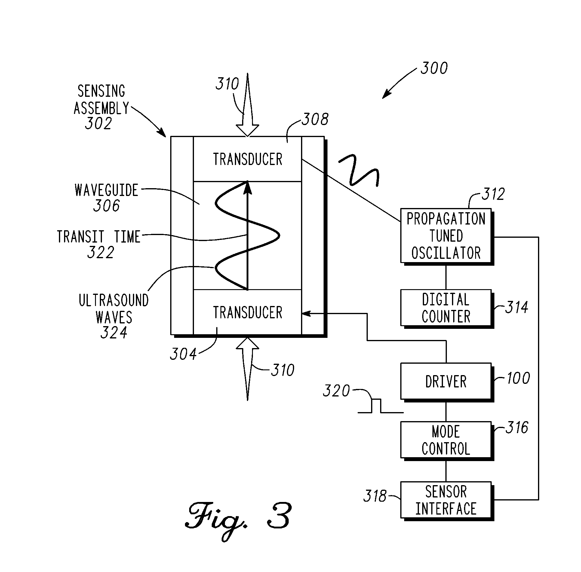
[0035] FIG. 3 is an exemplary propagation tuned oscillator (PTO) incorporating the transducer driver 100 to maintain positive closed-loop feedback in accordance with one embodiment. The PTO is provided to maintain positive closed-loop feedback of energy waves in the energy propagating structures of the sensing assembly 200. A positive feedback closed-loop circuit causes the oscillator to tune the resonant frequency of the energy waves in accordance with physical changes in the one or more energy propagating structures; hence the term, propagation tuned oscillator. The physical changes occur from compression or length changes resulting from externally applied forces or pressure. The physical changes in the energy propagating structures change in direct proportion to the external applied forces and can be precisely evaluated to measure the applied forces.
[0036] The sensing assembly 302 comprises a first transducer 304, a second transducer 308, and a waveguide 306 (energy propagating structure). In one embodiment, waveguide 306 is a compressible medium that contains, directs, and propagates energy waves coupled thereto. The sensing assembly 302 is affixed to load bearing or contacting surfaces 310. External forces applied to the contacting surfaces 310 compress the waveguide 306 and change the length of the waveguide 306. This also results in the transducers 304 and 308 being moved a similar distance closer together. This change in distance affects the transmit time 322 of energy waves 324 transmitted and received between transducers 304 and 308. The PTO 4 in response to these physical changes alters the oscillation frequency of the ultrasound waves 2 to achieve resonance. This is accomplished by way of the PTO 312 in conjunction with the transducer driver 100, the mode control 316 (e.g., continuous, pulse-loop, and pulse-echo), and sensor interface 318.
[0037] Notably, changes in the waveguide 306 (energy propagating structure or structures) alter the propagation properties of the medium of propagation (e.g. transmit time 322). Due to the closed-loop operation shown, the PTO 312 changes the resonant frequency of the oscillator and accordingly the frequency of oscillation of the closed loop circuit. In particular, the PTO 312 adjusts the oscillation frequency to be an integer number of waves. The digital counter 314 in conjunction with electronic components counts the number of waves to determine the corresponding change in the length of the waveguide 306. These changes in length change in direct proportion to the external force thus enabling the conversion of changes in parameter or parameters of interest into electrical signals.
[0038] The operation of the sensing system is described in more detail hereafter. The frequency of ultrasound waves 324 emitted by ultrasound resonator or transducer 304 is controlled by propagation tuned oscillator 312. The detecting ultrasound resonator or transducer 308 can be either a separate ultrasound resonator or transducer or the emitting resonator or transducer 304 itself depending on the selected mode of propagation. In the example where a single transducer is used, a reflecting surface reflects a propagated energy wave in waveguide 306 back to transducer 304 where it is detected by transducer 304 in a receiving mode. In either sensor example, propagation tuned oscillator enable the measurement of the transit time, frequency, or phase of energy waves through the medium.
[0039] The transit time 322 of ultrasound waves 324 through the waveguide determines the period of oscillation of propagation tuned oscillator 312. A change in external forces or conditions upon surfaces 310 affect the propagation characteristics of waveguide 306 and alter transit time 322. In one embodiment, the number of wavelengths of ultrasound waves 324 is held constant by propagation tuned oscillator 312. The constraint of having an integer number of wavelengths forces the frequency of oscillation of propagation tuned oscillator 312 to change. The resulting changes in frequency are captured with digital counter 314 as a measurement of changes in external forces or conditions applied to surfaces 310.
[0040] The closed loop measurement of the PTO enables high sensitivity and high signal-to-noise ratio closed-loop (time-based) measurements that are largely insensitive to most sources of error that may influence voltage or current driven sensing methods and devices. The resulting changes in the frequency of operation can be measured rapidly and with high resolution. This achieves the required measurement accuracy and precision thus capturing changes in the physical parameters of interest and enabling analysis of their dynamic and static behavior.
[0041] The level of accuracy and resolution achieved by the integration of energy transducers and an energy propagating structure or structures coupled with the electronic components of the propagation tuned oscillator enables the construction of, but is not limited to, compact ultra low power modules or devices for monitoring or measuring the parameters of interest. The flexibility to construct sensing modules or devices over a wide range of sizes enables sensing modules to be tailored to fit a wide range of applications such that the sensing module or device may be engaged with, or placed, attached, or affixed to, on, or within a body, instrument, appliance, vehicle, equipment, or other physical system and monitor or collect data on physical parameters of interest without disturbing the operation of the body, instrument, appliance, vehicle, equipment, or physical system.
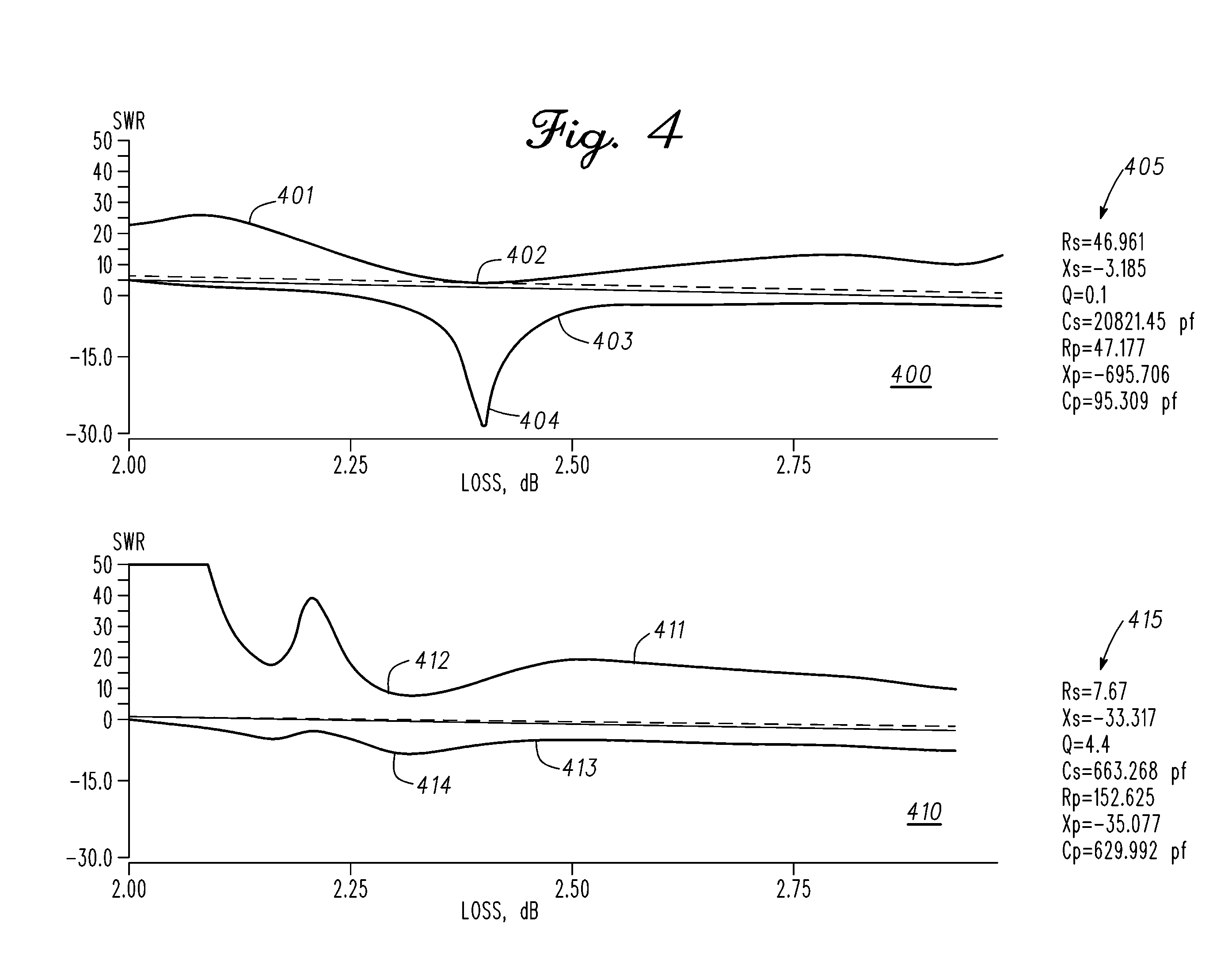
[0042] FIG. 4 is an example set of two graphs of frequency characteristics of an ultrasound piezoelectric transducer driven by the integrated transducer driver for two different configurations of adhesive and interfacing materials in accordance with an exemplary embodiment. The plots illustrate changes in the levels of standing wave ratio (SWR) and the efficiency of conversion of electrical signals to ultrasound output for a piezoelectric resonator or transducer with changes in the selection of adhesive and interfacing materials. The upper trace of values 401 in the top plot 400 illustrates the minimum level of SWR, 402 the lower trace 403 in the top plot 400 illustrates the minimum conversion loss 404 achieved with one selection of adhesive and interfacing materials. The equivalent electrical circuit of the associated transducer is identified in table 405.
[0043] The upper trace 411 of values in the bottom plot 410 illustrates the minimum value of SWR 412 and the lower trace 413 illustrates the minimum conversion loss 414 with a second selection of adhesive and interfacing materials, where required. The equivalent electrical circuit of the associated transducer is identified in table 415. In these plots, the combination of `loss` and `SWR` is an indication of the conversion efficiency of the ultrasound transducers at and around their resonant frequencies. The standing wave ratio is an indication of how much electrical energy is being reflected back into the driver circuitry from the interface with the transducer. The conversion loss is the loss of the unreflected electrical energy into ultrasound energy. The combination of the standing wave ratio with conversion loss is an indication of the total conversion efficiency of electrical energy into ultrasound energy for a given electrical driver circuit, matching network, and ultrasound resonator or transducer. The two plots indicate the sensitivity of standing wave ratio and conversion loss, and thus the level of the conversion efficiency, to differences in the structure and composition of different interfaces between the electrical circuitry and the ultrasound transducers. The optimal selection of adhesive and interfacing materials, where required, depends on many factors including, but not limited to, the composition, structure, and dimensions of the electronic substrate, piezoelectric components, and waveguides.
[0044] FIG. 5 is an illustration of a plot of non-overlapping resonant frequencies of paired transducers in accordance with an exemplary embodiment. In a non-limiting example, the characteristics of transducer A correspond to transducer 304 driven by the transducer driver 100. The characteristics of transducer B correspond to transducer 308 of sensing assemblage 302. Operation too close to their resonant frequencies results in substantial changes in phase, but limits shifts in frequency with changes in propagation through the waveguide or propagation medium. One approach to avoiding operation where the frequency of operation of an embodiment of a propagation tuned oscillator is bound this way is to select transducers with different resonant frequencies. The two transducers may be selected such that their respective series and parallel resonant frequencies do not overlap. That is, that both resonant frequencies of one transducer must be higher than either resonant frequency of the other transducer. This approach has the benefit of substantial, monotonic shifts in operating frequency of the present embodiment of a propagation tuned oscillator with changes in the transit time of energy or ultrasound waves within the waveguide or propagation medium with minimal signal processing, electrical components, and power consumption
[0045] Measurement of the changes in the physical length of individual ultrasound waveguides may be made in several modes. Each assemblage of one or two ultrasound resonators or transducers combined with an ultrasound waveguide may be controlled to operate in six different modes. This includes two wave shape modes: continuous wave or pulsed waves, and three propagation modes: reflectance, unidirectional, and bi-directional propagation of the ultrasound wave. The resolution of these measurements can be further enhanced by advanced processing of the measurement data to enable optimization of the trade-offs between measurement resolution versus length of the waveguide, frequency of the ultrasound waves, and the bandwidth of the sensing and data capture operations, thus achieving an optimal operating point for a sensing module or device.
[0046] FIG. 6 is a sensor interface diagram incorporating the transducer driver 100 in a continuous wave multiplexing arrangement for maintaining positive closed-loop feedback in accordance with one embodiment. The positive closed-loop feedback is illustrated by the bold line path. Initially, multiplexer (mux) 602 receives as input a clock signal 604, which is passed to the transducer driver 606 to produce the drive line signal 608. Analog multiplexer (mux) 610 receives drive line signal 608, which is passed to the transmitter transducer 612 to generate energy waves 614. Transducer 612 is located at a first location of an energy propagating medium. The emitted energy waves 614 propagate through the energy propagating medium. Receiver transducer 616 is located at a second location of the energy propagating medium. Receiver transducer 616 captures the energy waves 614, which are fed to analog mux 620 and passed to the zero-crossing receiver 624. The captured energy waves by transducer 616 are indicated by electrical waves 618 provided to mux 620. Zero-crossing receiver 624 outputs a pulse corresponding to each zero crossing detected from captured electrical waves 618. The zero crossings are counted and used to determine changes in the phase and frequency of the energy waves propagating through the energy propagating medium. In a non-limiting example, a parameter such as applied force is measured by relating the measured phase and frequency to a known relationship between the parameter (e.g. force) and the material properties of the energy propagating medium. In general, pulse sequence 622 corresponds to the detected signal frequency. The transducer driver 606 and the zero-crossing receiver 624 are in a feedback path of the propagation tuned oscillator. The pulse sequence 622 is coupled through mux 602 in a positive closed-loop feedback path. The pulse sequence 622 disables the clock signal 604 such that the path providing pulse sequence 622 is coupled to transducer driver 606 to continue emission of energy waves into the energy propagating medium and the path of clock signal 604 to driver 606 is disabled.
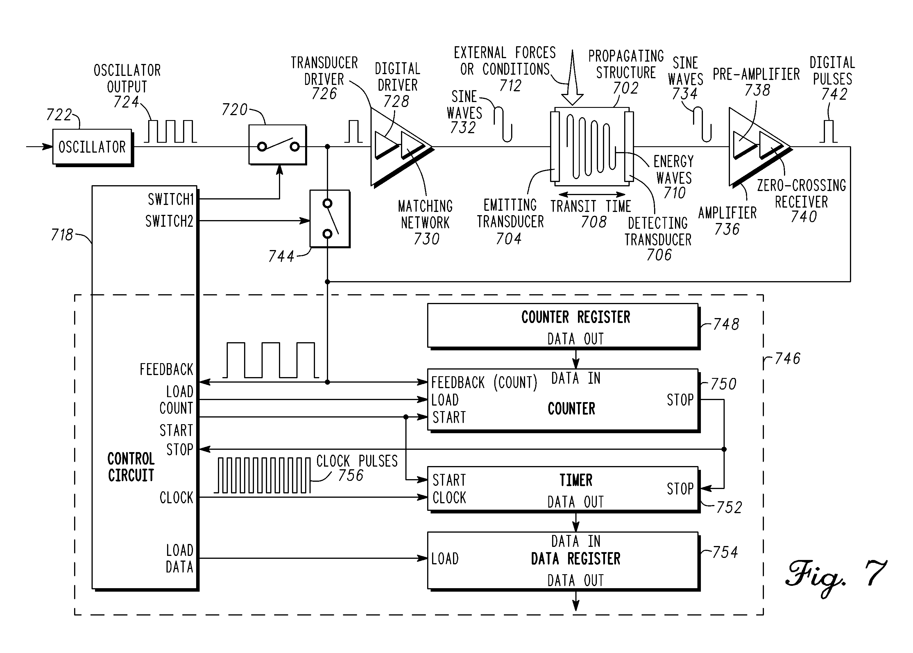
[0047] FIG. 7 is an exemplary block diagram of a propagation tuned oscillator (PTO) incorporating the transducer driver 100 for operation in continuous wave mode. In particular, with respect to FIG. 3, it illustrates closed loop measurement of the transit time 322 of ultrasound waves 324 within the waveguide 306 by the operation of the propagation tuned oscillator 312. This example is for operation in continuous wave mode. The system can also be operated in pulse mode and a pulse-echo mode. Pulse mode and pulsed echo-mode use a pulsed energy wave. Pulse-echo mode uses reflection to direct an energy wave within the energy propagation medium. Briefly, the digital logic circuit 746 digitizes the frequency of operation of the propagation tuned oscillator.
[0048] In continuous wave mode of operation a sensor comprising transducer 704, propagating structure 702, and transducer 706 is used to measure the parameter. In general, the parameter to be measured affects the properties of the propagating medium. For example, an external force or condition 712 is applied to propagating structure 702 that changes the length of the waveguide in a path of a propagating energy wave. A change in length corresponds to a change in transit time 708 of the propagating wave. Similarly, the length of propagating structure 702 corresponds to the applied force 712. A length reduction corresponds to a higher force being applied to the propagating structure 702. Conversely, a length increase corresponds to a lowering of the applied force 712 to the propagating structure 702. The length of propagating structure 702 is measured and is converted to force by way of a known length to force relationship.
[0049] Transducer 704 is an emitting device in continuous wave mode. The sensor for measuring a parameter comprises transducer 704 coupled to propagating structure 702 at a first location. A transducer 706 is coupled to propagating structure 702 at a second location. Transducer 706 is a receiving transducer for capturing propagating energy waves. In one embodiment, the captured propagated energy waves are electrical sine waves 734 that are output by transducer 706.
[0050] A measurement sequence is initiated when control circuitry 718 closes switch 720 coupling oscillator output 724 of oscillator 722 to the input of transducer driver 726. One or more pulses provided to transducer driver 726 initiates an action to propagate energy waves 710 having simple or complex waveforms through energy propagating structure or medium 702. Transducer driver 726 comprises a digital driver 728 and matching network 730. In one embodiment, transducer driver 726 transforms the oscillator output of oscillator 722 into sine waves of electrical waves 732 having the same repetition rate as oscillator output 724 and sufficient amplitude to excite transducer 704.
[0051] Emitting transducer 704 converts the sine waves 732 into energy waves 710 of the same frequency and emits them at the first location into energy propagating structure or medium 702. The energy waves 710 propagate through energy propagating structure or medium 702. Upon reaching transducer 706 at the second location, energy waves 710 are captured, sensed, or detected. The captured energy waves are converted by transducer 706 into sine waves 734 that are electrical waves having the same frequency.
[0052] Amplifier 736 comprises a pre-amplifier 738 and zero-cross receiver 740. Amplifier 736 converts the sine waves 734 into digital pulses 742 of sufficient duration to sustain the behavior of the closed loop circuit. Control circuitry 718 responds to digital pulses 742 from amplifier 736 by opening switch 720 and closing switch 744. Opening switch 720 decouples oscillator output 724 from the input of transducer driver 726. Closing switch 744 creates a closed loop circuit coupling the output of amplifier 736 to the input of transducer driver 726 and sustaining the emission, propagation, and detection of energy waves through energy propagating structure or medium 702.
[0053] An equilibrium state is attained by maintaining unity gain around this closed loop circuit wherein sine waves 732 input into transducer 704 and sine waves 734 output by transducer 706 are in phase with a small but constant offset. Transducer 706 as disclosed above, outputs the sine waves 734 upon detecting energy waves propagating to the second location. In the equilibrium state, an integer number of energy waves 710 propagate through energy propagating structure or medium 702.
[0054] Movement or changes in the physical properties of energy propagating structure or medium 702 change a transit time 708 of energy waves 710. The transit time 708 comprises the time for an energy wave to propagate from the first location to the second location of propagating structure 702. Thus, the change in the physical property of propagating structure 702 results in a corresponding time period change of the energy waves 710 within energy propagating structure or medium 702. These changes in the time period of the energy waves 710 alter the equilibrium point of the closed loop circuit and frequency of operation of the closed loop circuit. The closed loop circuit adjusts such that sine waves 732 and 734 correspond to the new equilibrium point. The frequency of energy waves 710 and changes to the frequency correlate to changes in the physical attributes of energy propagating structure or medium 702.
[0055] The physical changes may be imposed on energy propagating structure 702 by external forces or conditions 712 thus translating the levels and changes of the parameter or parameters of interest into signals that may be digitized for subsequent processing, storage, and display. Translation of the operating frequency into digital binary numbers facilitates communication, additional processing, storage, and display of information about the level and changes in physical parameters of interest. Similarly, the frequency of energy waves 710 during the operation of the closed loop circuit, and changes in this frequency, may be used to measure movement or changes in physical attributes of energy propagating structure or medium 702.
[0056] Prior to measurement of the frequency or operation of the propagation tuned oscillator, control logic 718 loads the loop count into digital counter 750 that is stored in count register 748. The first digital pulses 742 initiates closed loop operation within the propagation tuned oscillator and signals control circuit 718 to start measurement operations. At the start of closed loop operation, control logic 718 enables digital counter 750 and digital timer 752. In one embodiment, digital counter 750 decrements its value on the rising edge of each digital pulse output by zero-cross receiver 740. Digital timer 752 increments its value on each rising edge of clock pulses 756. When the number of digital pulses 742 has decremented, the value within digital counter 750 to zero a stop signal is output from digital counter 750. The stop signal disables digital timer 752 and triggers control circuit 718 to output a load command to data register 754. Data register 754 loads a binary number from digital timer 752 that is equal to the period of the energy waves or pulses times the value in counter 748 divided by clock period 756. With a constant clock period 756, the value in data register 754 is directly proportional to the aggregate period of the energy waves or pulses accumulated during the measurement operation. Duration of the measurement operation and the resolution of measurements may be adjusted by increasing or decreasing the value preset in the count register 748.
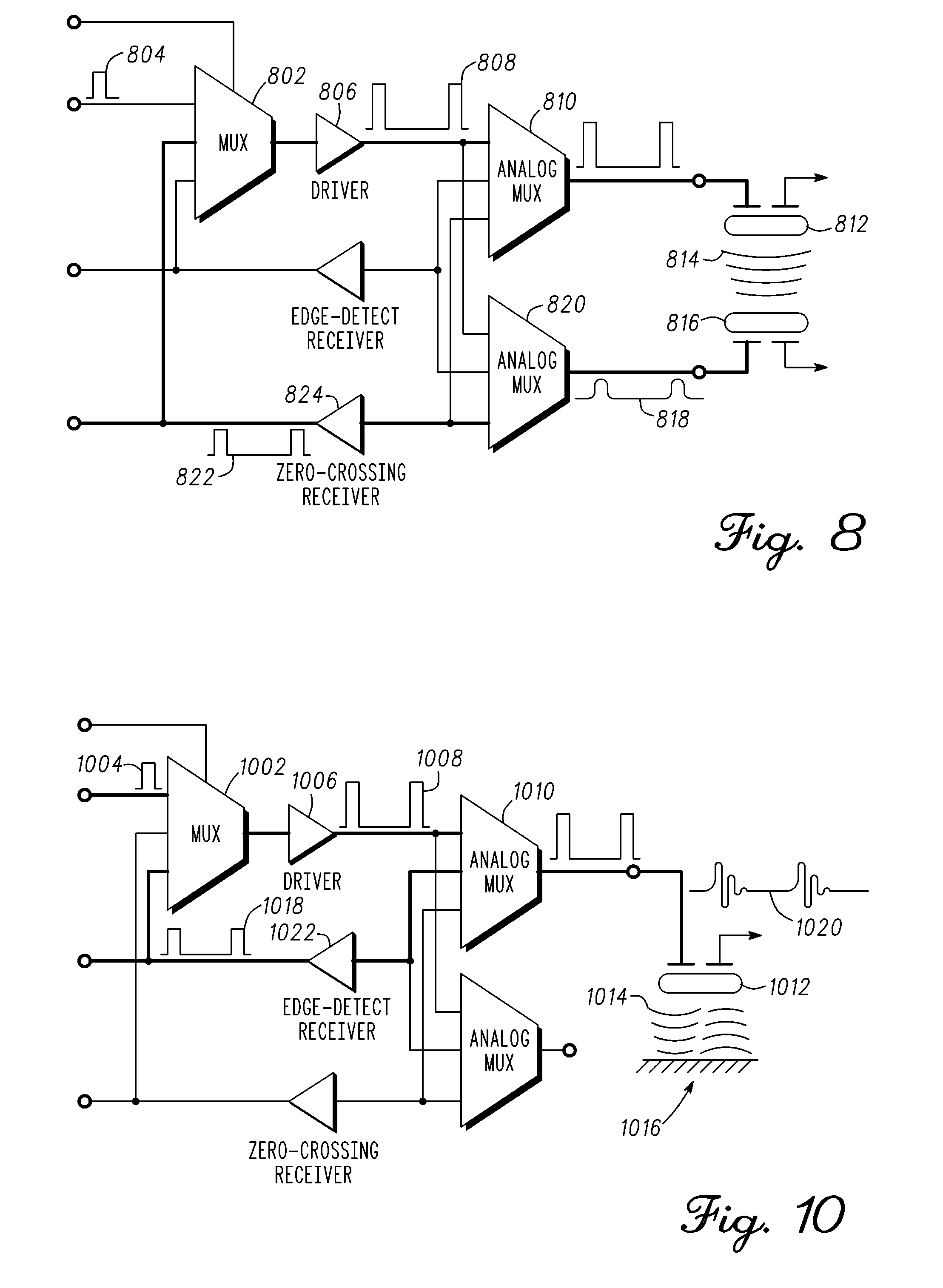
[0057] FIG. 8 is a sensor interface diagram incorporating the transducer driver 100 in a pulse multiplexing arrangement for maintaining positive closed-loop feedback in accordance with one embodiment. In one embodiment, the circuitry other than the sensor is integrated on an application specific integrated circuit (ASIC). The positive closed-loop feedback is illustrated by the bold line path. Initially, mux 802 is enabled to couple one or more digital pulses 804 to the transducer driver 806. Transducer driver 806 generates a pulse sequence 808 corresponding to digital pulses 804. Analog mux 810 is enabled to couple pulse sequence 808 to the transmitter transducer 812. Transducer 812 is coupled to a medium at a first location. Transducer 812 responds to pulse sequence 808 and generates corresponding energy pulses 814 that are emitted into the medium at the first location. The energy pulses 814 propagate through the medium. A receiver transducer 816 is located at a second location on the medium. Receiver transducer 816 captures the energy pulses 814 and generates a corresponding signal of electrical pulses 818. Transducer 816 is coupled to a mux 820. Mux 820 is enabled to couple to zero-cross receiver 824. Electrical pulses 818 from transducer 816 are coupled to zero-cross receiver 824. Zero-cross receiver 824 counts zero crossings of electrical pulses 818 to determine changes in phase and frequency of the energy pulses responsive to an applied force, as previously explained. Zero-cross receiver 824 outputs a pulse sequence 822 corresponding to the detected signal frequency. Pulse sequence 822 is coupled to mux 802. Mux 802 is decoupled from coupling digital pulses 804 to driver 806 upon detection of pulses 822. Conversely, mux 802 is enabled to couple pulses 822 to driver 806 upon detection of pulses 822 thereby creating a positive closed-loop feedback path. Thus, in pulse mode, transducer driver 806 and zero-cross receiver 824 is part of the closed-loop feedback path that continues emission of energy pulses into the medium at the first location and detection at the second location to measure a transit time and changes in transit time of pulses through the medium.
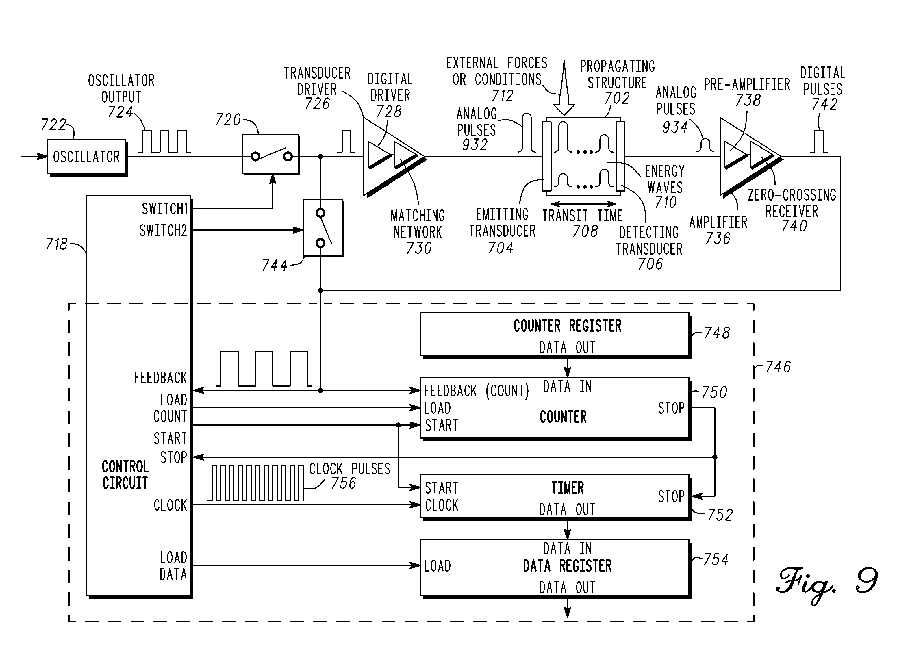
[0058] FIG. 9 is an exemplary block diagram of a propagation tuned oscillator (PTO) incorporating the transducer driver 100 for operation in pulse mode. In particular, with respect to FIG. 3, it illustrates closed loop measurement of the transit time 322 of ultrasound waves 324 within the waveguide 306 by the operation of the propagation tuned oscillator 312. This example is for operation in pulse mode. The system can also be operated in continuous wave mode and a pulse-echo mode. Continuous wave mode uses a continuous wave signal. Pulse-echo mode uses reflection to direct an energy wave within the energy propagation medium. Briefly, the digital logic circuit 746 digitizes the frequency of operation of the propagation tuned oscillator.
[0059] In pulse mode of operation, a sensor comprising transducer 704, propagating structure 702, and transducer 706 is used to measure the parameter. In general, the parameter to be measured affects the properties of the propagating medium. For example, an external force or condition 712 is applied to propagating structure 702 that changes the length of the waveguide in a path of a propagating energy wave. A change in length corresponds to a change in transit time 708 of the propagating wave. The length of propagating structure 702 is measured and is converted to force by way of a known length to force relationship. One benefit of pulse mode operation is the use of a high magnitude pulsed energy wave. In one embodiment, the magnitude of the energy wave decays as it propagates through the medium. The use of a high magnitude pulse is a power efficient method to produce a detectable signal if the energy wave has to traverse a substantial distance or is subject to a reduction in magnitude as it propagated due to the medium.
[0060] A measurement sequence is initiated when control circuitry 718 closes switch 720 coupling oscillator output 724 of oscillator 722 to the input of transducer driver 726. One or more pulses provided to transducer driver 726 initiates an action to propagate energy waves 710 having simple or complex waveforms through energy propagating structure or medium 702. Transducer driver 726 comprises a digital driver 728 and matching network 730. In one embodiment, transducer driver 726 transforms the oscillator output of oscillator 722 into analog pulses of electrical waves 932 having the same repetition rate as oscillator output 724 and sufficient amplitude to excite transducer 704.
[0061] Emitting transducer 704 converts the analog pulses 932 into energy waves 710 of the same frequency and emits them at a first location into energy propagating structure or medium 702. The energy waves 710 propagate through energy propagating structure or medium 702. Upon reaching transducer 706 at the second location, energy waves 710 are captured, sensed, or detected. The captured energy waves are converted by transducer 706 into analog pulses 934 that are electrical waves having the same frequency.
[0062] Amplifier 736 comprises a pre-amplifier 738 and zero-cross receiver 740. Amplifier 736 converts the analog pulses 934 into digital pulses 742 of sufficient duration to sustain the behavior of the closed loop circuit. Control circuitry 718 responds to digital pulses 742 from amplifier 736 by opening switch 720 and closing switch 744. Opening switch 720 decouples oscillator output 724 from the input of transducer driver 726. Closing switch 744 creates a closed loop circuit coupling the output of amplifier 736 to the input of transducer driver 726 and sustaining the emission, propagation, and detection of energy waves through energy propagating structure or medium 702.
[0063] An equilibrium state is attained by maintaining unity gain around this closed loop circuit wherein pulses 932 input into transducer 704 and pulses 934 output by transducer 706 are in phase with a small but constant offset. Transducer 706 as disclosed above, outputs the pulses 934 upon detecting energy waves propagating to the second location. In the equilibrium state, an integer number of energy waves 710 propagate through energy propagating structure or medium 702.
[0064] Movement or changes in the physical properties of energy propagating structure or medium 702 change a transit time 708 of energy waves 710. The transit time 708 comprises the time for an energy wave to propagate from the first location to the second location of propagating structure 702. Thus, the change in the physical property of propagating structure 702 results in a corresponding time period change of the energy waves 710 within energy propagating structure or medium 702. These changes in the time period of the energy waves 710 alter the equilibrium point of the closed loop circuit and frequency of operation of the closed loop circuit. The closed loop circuit adjusts such that pulses 932 and 934 correspond to the new equilibrium point. The frequency of energy waves 710 and changes to the frequency correlate to changes in the physical attributes of energy propagating structure or medium 702.
[0065] The physical changes may be imposed on energy propagating structure 702 by external forces or conditions 712 thus translating the levels and changes of the parameter or parameters of interest into signals that may be digitized for subsequent processing, storage, and display. Translation of the operating frequency into digital binary numbers facilitates communication, additional processing, storage, and display of information about the level and changes in physical parameters of interest as disclosed in more detail hereinabove. Similarly, the frequency of energy waves 710 during the operation of the closed loop circuit, and changes in this frequency, may be used to measure movement or changes in physical attributes of energy propagating structure or medium 702.
[0066] Briefly referring back to FIG. 5 an exemplary plot of non-overlapping resonant frequencies of paired transducers was shown. One approach to avoiding operation where the frequency of operation of a propagation tuned oscillator is bound this way is to select transducers with different resonant frequencies. The two transducers are selected such that their respective series and parallel resonant frequencies do not overlap. That is, that both resonant frequencies of one transducer are higher than either resonant frequency of the other transducer.
[0067] FIG. 10 is a sensor interface diagram incorporating the transducer driver 100 in a pulse-echo multiplexing arrangement for maintaining positive closed-loop feedback in accordance with one embodiment. The positive closed-loop feedback is illustrated by the bold line path. Initially, multiplexer (mux) 1002 receives as input a digital pulse 1004, which is passed to the transducer driver 1006 to produce the pulse sequence 1008. Analog multiplexer (mux) 1010 receives pulse sequence 1008, which is passed to the transducer 1012 to generate energy pulses 1014. Energy pulses 1014 are emitted into a first location of a medium and propagate through the medium. In the pulse-echo example, energy pulses 1014 are reflected off a surface 1016 at a second location of the medium, for example, the end of a waveguide or reflector, and echoed back to the transducer 1012. The transducer 1012 proceeds to then capture the reflected pulse echo. In pulsed echo mode, the transducer 1012 performs as both a transmitter and a receiver. As disclosed above, transducer 1012 toggles back and forth between emitting and receiving energy waves. Transducer 1012 captures the reflected echo pulses, which are coupled to analog mux 1010 and directed to the edge-detect receiver 1022. The captured reflected echo pulses is indicated by electrical waves 1018. Edge-detect receiver 1022 locks on pulse edges corresponding to the wave front of a propagated energy wave to determine changes in phase and frequency of the energy pulses 1014 responsive to an applied force, as previously explained. Among other parameters, it generates a pulse sequence 1018 corresponding to the detected signal frequency. The pulse sequence 1018 is coupled to mux 1002 and directed to driver 1006 to initiate one or more energy waves being emitted into the medium by transducer 1012. Pulse 1004 is decoupled from being provided to driver 1006. Thus, a positive closed loop feedback including transducer driver 1006 is formed that repeatably emits energy waves into the medium until mux 1002 prevents a signal from being provided to driver 1006. The edge-detect receiver 1022 is coupled to a second location of the medium and is in the feedback path. The edge-detect receiver 1002 initiates a pulsed energy wave being provided at the first location of the medium upon detecting a wave front at the second location when the feedback path is closed.
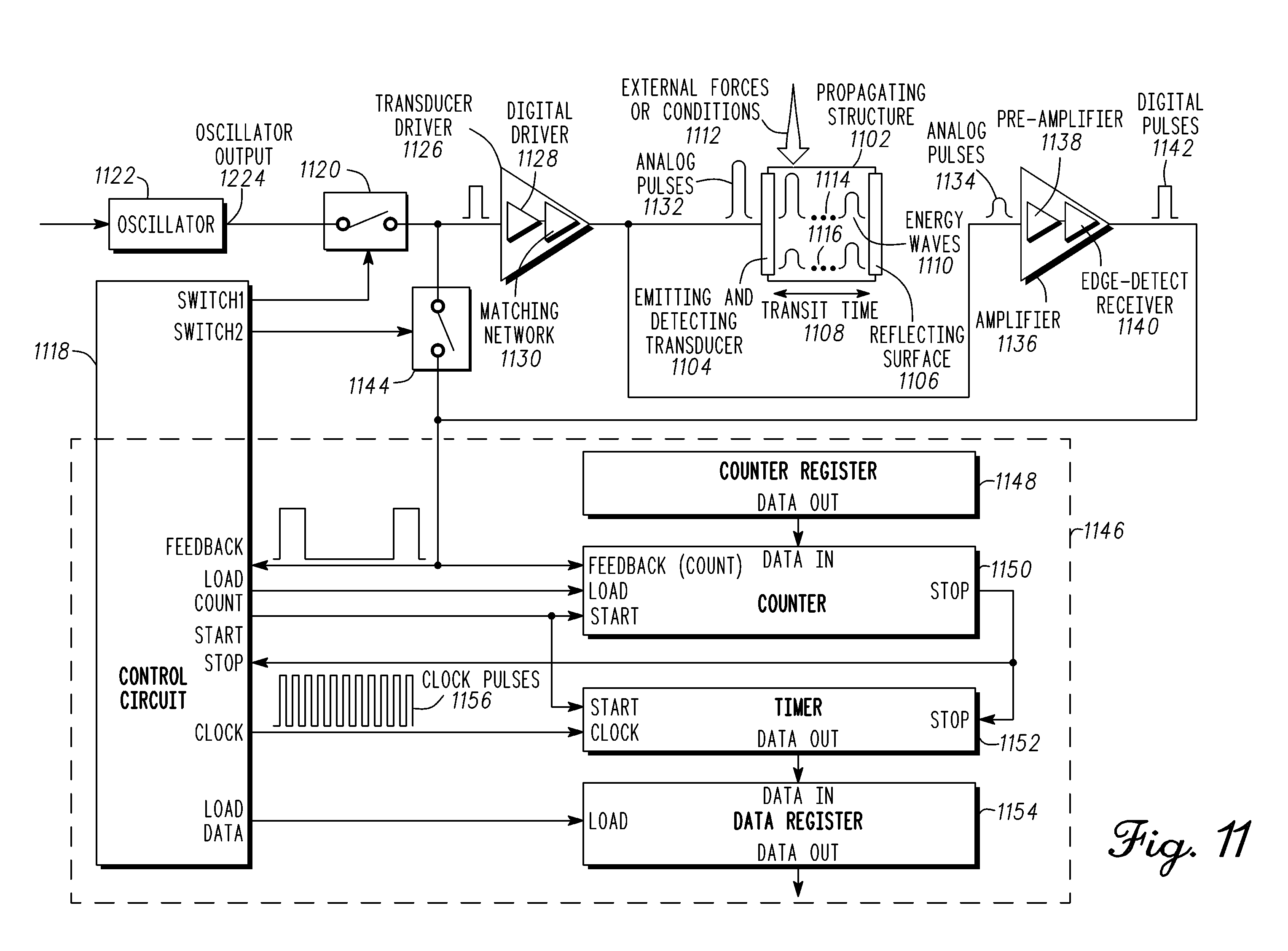
[0068] FIG. 11 is an exemplary block diagram of a propagation tuned oscillator (PTO) incorporating the transducer driver 100 for operation in pulse echo mode. In particular, with respect to FIG. 3, it illustrates closed loop measurement of the transit time 322 of ultrasound waves 324 within the waveguide 306 by the operation of the propagation tuned oscillator 312. This example is for operation in a pulse echo mode. The system can also be operated in pulse mode and a continuous wave mode. Pulse mode does not use a reflected signal. Continuous wave mode uses a continuous signal. Briefly, the digital logic circuit 1146 digitizes the frequency of operation of the propagation tuned oscillator.
[0069] In pulse-echo mode of operation a sensor comprising transducer 1104, propagating structure 1102, and reflecting surface 1106 is used to measure the parameter. In general, the parameter to be measured affects the properties of the propagating medium. For example, an external force or condition 1112 is applied to propagating structure 1102 that changes the length of the waveguide in a path of a propagating energy wave. A change in length corresponds to a change in transit time of the propagating wave. Similarly, the length of propagating structure 1102 corresponds to the applied force 1112. A length reduction corresponds to a higher force being applied to the propagating structure 1102. Conversely, a length increase corresponds to a lowering of the applied force 1112 to the propagating structure 1102. The length of propagating structure 1102 is measured and is converted to force by way of a known length to force relationship.
[0070] Transducer 1104 is both an emitting device and a receiving device in pulse-echo mode. The sensor for measuring a parameter comprises transducer 1104 coupled to propagating structure 1102 at a first location. A reflecting surface is coupled to propagating structure 1102 at a second location. Transducer 1104 has two modes of operation comprising an emitting mode and receiving mode. Transducer 1104 emits an energy wave into the propagating structure 1102 at the first location in the emitting mode. The energy wave propagates to a second location and is reflected by reflecting surface 1106. The reflected energy wave is reflected towards the first location and transducer 1104 subsequently generates a signal in the receiving mode corresponding to the reflected energy wave.
[0071] A measurement sequence in pulse echo mode is initiated when control circuitry 1118 closes switch 1120 coupling digital output 1124 of oscillator 1122 to the input of transducer driver 1126. One or more pulses provided to transducer driver 1126 starts a process to emit one or more energy waves 1110 having simple or complex waveforms into energy propagating structure or medium 1102. Transducer driver 1126 comprises a digital driver 1128 and matching network 1130. In one embodiment, transducer driver 1126 transforms the digital output of oscillator 1122 into pulses of electrical waves 1132 having the same repetition rate as digital output 1124 and sufficient amplitude to excite transducer 1104.
[0072] Transducer 1104 converts the pulses of electrical waves 1132 into pulses of energy waves 1110 of the same repetition rate and emits them into energy propagating structure or medium 1102. The pulses of energy waves 1110 propagate through energy propagating structure or medium 1102 as shown by arrow 1114 towards reflecting surface 1106. Upon reaching reflecting surface 1106, energy waves 1110 are reflected by reflecting surface 1106. Reflected energy waves propagate towards transducer 1104 as shown by arrow 1116. The reflected energy waves are detected by transducer 1104 and converted into pulses of electrical waves 1134 having the same repetition rate.
[0073] Amplifier 1136 comprises a pre-amplifier 1138 and edge-detect receiver 1140. Amplifier 1136 converts the pulses of electrical waves 1134 into digital pulses 1142 of sufficient duration to sustain the pulse behavior of the closed loop circuit. Control circuitry 1118 responds to digital output pulses 1142 from amplifier 1136 by opening switch 1120 and closing switch 1144. Opening switch 1120 decouples oscillator output 1124 from the input of transducer driver 1126. Closing switch 1144 creates a closed loop circuit coupling the output of amplifier 1136 to the input of transducer driver 1126 and sustaining the emission, propagation, and detection of energy pulses through energy propagating structure or medium 1102.
[0074] An equilibrium state is attained by maintaining unity gain around this closed loop circuit wherein electrical waves 1132 input into transducer 1104 and electrical waves 1134 output by transducer 1104 are in phase with a small but constant offset. Transducer 1104 as disclosed above, outputs the electrical waves 1134 upon detecting reflected energy waves reflected from reflecting surface 1106. In the equilibrium state, an integer number of pulses of energy waves 1110 propagate through energy propagating structure or medium 1102.
[0075] Movement or changes in the physical properties of energy propagating structure or medium 1102 change a transit time 1108 of energy waves 1110. The transit time 1108 comprises the time for an energy wave to propagate from the first location to the second location of propagating structure 1102 and the time for the reflected energy wave to propagate from the second location to the first location of propagating structure 1102. Thus, the change in the physical property of propagating structure 1102 results in a corresponding time period change of the energy waves 1110 within energy propagating structure or medium 1102. These changes in the time period of the repetition rate of the energy pulses 1110 alter the equilibrium point of the closed loop circuit and repetition rate of operation of the closed loop circuit. The closed loop circuit adjusts such that electrical waves 1132 and 1134 correspond to the new equilibrium point. The repetition rate of energy waves 1110 and changes to the repetition rate correlate to changes in the physical attributes of energy propagating structure or medium 1102.
[0076] The physical changes may be imposed on energy propagating structure 1102 by external forces or conditions 1112 thus translating the levels and changes of the parameter or parameters of interest into signals that may be digitized for subsequent processing, storage, and display. Translation of the operating frequency into digital binary numbers facilitates communication, additional processing, storage, and display of information about the level and changes in physical parameters of interest. Similarly, the frequency of energy waves 1110 during the operation of the closed loop circuit, and changes in this frequency, may be used to measure movement or changes in physical attributes of energy propagating structure or medium 1102.
[0077] Prior to measurement of the frequency or operation of the propagation tuned oscillator, control logic 1118 loads the loop count into digital counter 1150 that is stored in count register 1148. The first digital pulses 1142 initiates closed loop operation within the propagation tuned oscillator and signals control circuit 1118 to start measurement operations. At the start of closed loop operation, control logic 1118 enables digital counter 1150 and digital timer 1152. In one embodiment, digital counter 1150 decrements its value on the rising edge of each digital pulse output by edge-detect receiver 1140. Digital timer 1152 increments its value on each rising edge of clock pulses 1156. When the number of digital pulses 1142 has decremented, the value within digital counter 1150 to zero a stop signal is output from digital counter 1150. The stop signal disables digital timer 1152 and triggers control circuit 1118 to output a load command to data register 1154. Data register 1154 loads a binary number from digital timer 1152 that is equal to the period of the energy waves or pulses times the value in counter 1148 divided by clock period 1156. With a constant clock period 1156, the value in data register 1154 is directly proportional to the aggregate period of the energy waves or pulses accumulated during the measurement operation. Duration of the measurement operation and the resolution of measurements may be adjusted by increasing or decreasing the value preset in the count register 1148.
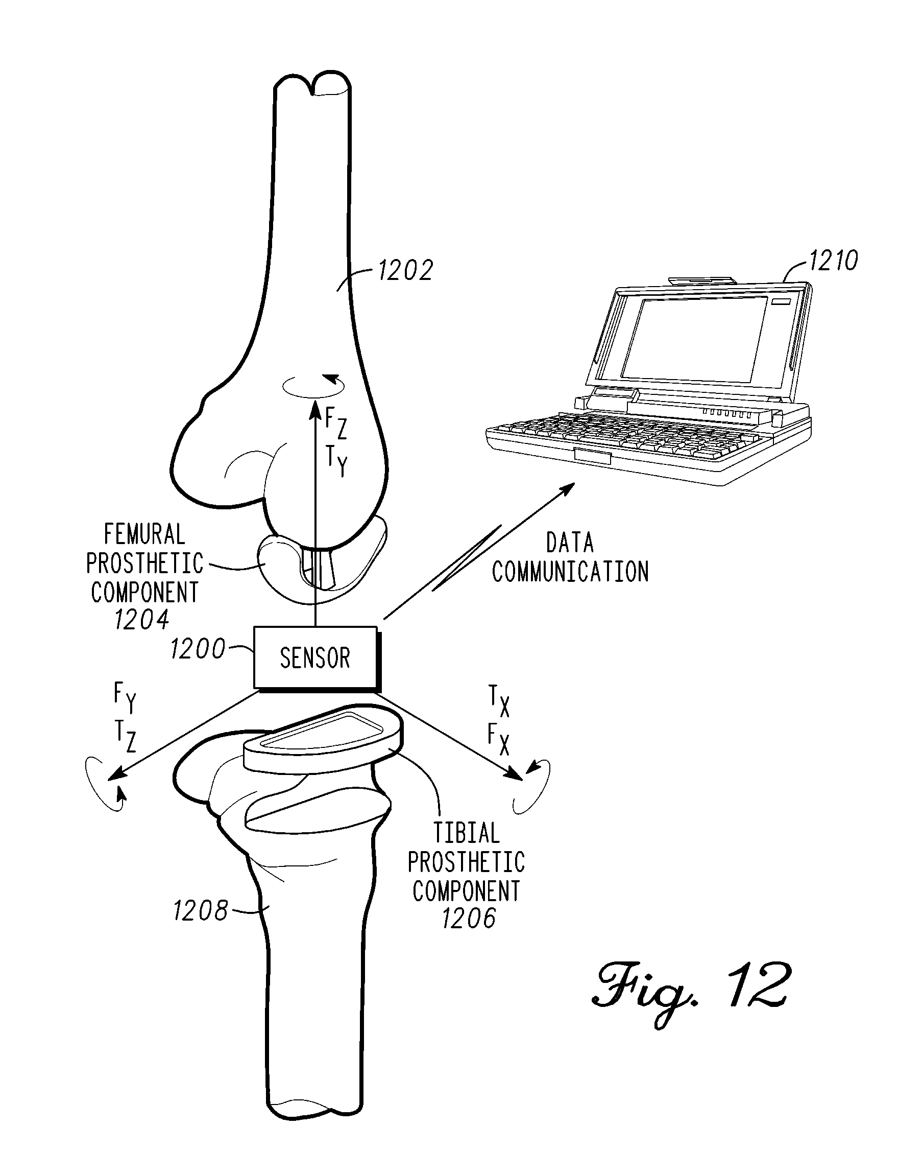
[0078] FIG. 12 is an illustration of a sensor 1200 placed in contact between a femur 1202 and a tibia 1208 for measuring a parameter in accordance with an exemplary embodiment. In general, a sensor 1200 is placed in contact with or in proximity to the muscular-skeletal system to measure a parameter. In a non-limiting example, sensor 1200 can be operated in continuous wave mode, pulse mode, and pulse echo-mode to measure a parameter of a joint or an artificial joint. Embodiments of sensor 1200 are broadly directed to measurement of physical parameters, and more particularly, to evaluating changes in the transit time of a pulsed energy wave propagating through a medium. In-situ measurements during orthopedic joint implant surgery would be of substantial benefit to verify an implant is in balance and under appropriate loading or tension. In one embodiment, the instrument is similar to and operates familiarly with other instruments currently used by surgeons. This will increase acceptance and reduce the adoption cycle for a new technology. The measurements will allow the surgeon to ensure that the implanted components are installed within predetermined ranges that maximize the working life of the joint prosthesis and reduce costly revisions. Providing quantitative measurement and assessment of the procedure using real-time data will produce results that are more consistent. A further issue is that there is little or no implant data generated from the implant surgery, post-operatively, and long term. Sensor 1200 can provide implant status data to the orthopedic manufacturers and surgeons. Moreover, data generated by direct measurement of the implanted joint itself would greatly improve the knowledge of implanted joint operation and joint wear thereby leading to improved design and materials.
[0079] In at least one exemplary embodiment, an energy pulse is directed within one or more waveguides in sensor 1200 by way of pulse mode operations and pulse shaping. The waveguide is a conduit that directs the energy pulse in a predetermined direction. The energy pulse is typically confined within the waveguide. In one embodiment, the waveguide comprises a polymer material. For example, urethane or polyethylene are polymers suitable for forming a waveguide. The polymer waveguide can be compressed and has little or no hysteresis in the system. Alternatively, the energy pulse can be directed through the muscular-skeletal system. In one embodiment, the energy pulse is directed through bone of the muscular-skeletal system to measure bone density. A transit time of an energy pulse is related to the material properties of a medium through which it traverses. This relationship is used to generate accurate measurements of parameters such as distance, weight, strain, pressure, wear, vibration, viscosity, and density to name but a few.
[0080] Sensor 1200 can be size constrained by form factor requirements of fitting within a region the muscular-skeletal system or a component such as a tool, equipment, or artificial joint. In a non-limiting example, sensor 1200 is used to measure load and balance of an installed artificial knee joint. A knee prosthesis comprises a femoral prosthetic component 1204, an insert, and a tibial prosthetic component 1206. A distal end of femur 1202 is prepared and receives femoral prosthetic component 1204. Femoral prosthetic component 1204 typically has two condyle surfaces that mimic a natural femur. As shown, femoral prosthetic component 1204 has single condyle surface being coupled to femur 1202. Femoral prosthetic component 1204 is typically made of a metal or metal alloy.
[0081] A proximal end of femur 1208 is prepared to receive tibial prosthetic component 1206. Tibial prosthetic component 1206 is a support structure that is fastened to the proximal end of the tibia and is usually made of a metal or metal alloy. The tibial prosthetic component 1206 also retains the insert in a fixed position with respect to femur 1208. The insert is fitted between femoral prosthetic component 1204 and tibial prosthetic component 1206. The insert has at least one bearing surface that is in contact with at least condyle surface of femoral prosthetic component 1204. The condyle surface can move in relation to the bearing surface of the insert such that the lower leg can rotate under load. The insert is typically made of a high wear plastic material that minimizes friction.
[0082] In a knee joint replacement process, the surgeon affixes femoral prosthetic component 1204 to the femur 1202 and tibial prosthetic component 1206 to femur 1208. The tibial prosthetic component 1206 can include a tray or plate affixed to the planarized proximal end of the femur 1208. Sensor 1200 is placed between a condyle surface of femoral prosthetic component 1204 and a major surface of tibial prosthetic component 1206. The condyle surface contacts a major surface of sensor 1200. The major surface of sensor 1200 approximates a surface of the insert. Tibial prosthetic component 1206 can include a cavity or tray on the major surface that receives and retains sensor 1200 during a measurement process. Tibial prosthetic component 1206 and sensor 1200 has a combined thickness that represents a combined thickness of tibial prosthetic component 1206 and a final (or chronic) insert of the knee joint.
[0083] In one embodiment, two sensors 1200 are fitted into two separate cavities, the cavities are within a trial insert (that may also be referred to as the tibial insert, rather than the tibial component itself) that is held in position by tibial component 1206. One or two sensors 1200 may be inserted between femoral prosthetic component 1204 and tibial prosthetic component 1206. Each sensor is independent and each measures a respective condyle of femur 1202. Separate sensors also accommodate a situation where a single condyle is repaired and only a single sensor is used. Alternatively, the electronics can be shared between two sensors to lower cost and complexity of the system. The shared electronics can multiplex between each sensor module to take measurements when appropriate. Measurements taken by sensor 1200 aid the surgeon in modifying the absolute loading on each condyle and the balance between condyles. Although shown for a knee implant, sensor 1200 can be used to measure other orthopedic joints such as the spine, hip, shoulder, elbow, ankle, wrist, interphalangeal joint, metatarsophalangeal joint, metacarpophalangeal joints, and others. Alternatively, sensor 1200 can also be adapted to orthopedic tools to provide measurements.
[0084] The prosthesis incorporating sensor 1200 emulates the function of a natural knee joint. Sensor 1200 can measure loads or other parameters at various points throughout the range of motion. Data from sensor 1200 is transmitted to a receiving station 1210 via wired or wireless communications. In a first embodiment, sensor 1200 is a disposable system. Sensor 1200 can be disposed of after using sensor 1200 to optimally fit the joint implant. Sensor 1200 is a low cost disposable system that reduces capital costs, operating costs, facilitates rapid adoption of quantitative measurement, and initiates evidentiary based orthopedic medicine. In a second embodiment, a methodology can be put in place to clean and sterilize sensor 1200 for reuse. In a third embodiment, sensor 1200 can be incorporated in a tool instead of being a component of the replacement joint. The tool can be disposable or be cleaned and sterilized for reuse. In a fourth embodiment, sensor 1200 can be a permanent component of the replacement joint. Sensor 1200 can be used to provide both short term and long term post-operative data on the implanted joint. In a fifth embodiment, sensor 1200 can be coupled to the muscular-skeletal system. In all of the embodiments, receiving station 1210 can include data processing, storage, or display, or combination thereof and provide real time graphical representation of the level and distribution of the load. Receiving station 1210 can record and provide accounting information of sensor 1200 to an appropriate authority.
[0085] In an intra-operative example, sensor 1200 can measure forces (Fx, Fy, Fz) with corresponding locations and torques (e.g. Tx, Ty, and Tz) on the femoral prosthetic component 1204 and the tibial prosthetic component 1206. The measured force and torque data is transmitted to receiving station 1210 to provide real-time visualization for assisting the surgeon in identifying any adjustments needed to achieve optimal joint pressure and balancing. The data has substantial value in determining ranges of load and alignment tolerances required to minimize rework and maximize patient function and longevity of the joint.
[0086] As mentioned previously, sensor 1200 can be used for other joint surgeries; it is not limited to knee replacement implant or implants. Moreover, sensor 1200 is not limited to trial measurements. Sensor 1200 can be incorporated into the final joint system to provide data post-operatively to determine if the implanted joint is functioning correctly. Early determination of a problem using sensor 1200 can reduce catastrophic failure of the joint by bringing awareness to a problem that the patient cannot detect. The problem can often be rectified with a minimal invasive procedure at lower cost and stress to the patient. Similarly, longer term monitoring of the joint can determine wear or misalignment that if detected early can be adjusted for optimal life or replacement of a wear surface with minimal surgery thereby extending the life of the implant. In general, sensor 1200 can be shaped such that it can be placed or engaged or affixed to or within load bearing surfaces used in many orthopedic applications (or used in any orthopedic application) related to the musculoskeletal system, joints, and tools associated therewith. Sensor 1200 can provide information on a combination of one or more performance parameters of interest such as wear, stress, kinematics, kinetics, fixation strength, ligament balance, anatomical fit and balance.
[0087] The present invention is applicable to a wide range of medical and nonmedical applications including, but not limited to, frequency compensation; control of, or alarms for, physical systems; or monitoring or measuring physical parameters of interest. The level of accuracy and repeatability attainable in a highly compact sensing module or device may be applicable to many medical applications monitoring or measuring physiological parameters throughout the human body including, not limited to, bone density, movement, viscosity, and pressure of various fluids, localized temperature, etc. with applications in the vascular, lymph, respiratory, digestive system, muscles, bones, and joints, other soft tissue areas, and interstitial fluids.
[0088] While the present invention has been described with reference to particular embodiments, those skilled in the art will recognize that many changes may be made thereto without departing from the spirit and scope of the present invention. Each of these embodiments and obvious variations thereof is contemplated as falling within the spirit and scope of the invention.
* * * * *
D00000
D00001
D00002
D00003
D00004
D00005
D00006
D00007
D00008
D00009
XML
uspto.report is an independent third-party trademark research tool that is not affiliated, endorsed, or sponsored by the United States Patent and Trademark Office (USPTO) or any other governmental organization. The information provided by uspto.report is based on publicly available data at the time of writing and is intended for informational purposes only.
While we strive to provide accurate and up-to-date information, we do not guarantee the accuracy, completeness, reliability, or suitability of the information displayed on this site. The use of this site is at your own risk. Any reliance you place on such information is therefore strictly at your own risk.
All official trademark data, including owner information, should be verified by visiting the official USPTO website at www.uspto.gov. This site is not intended to replace professional legal advice and should not be used as a substitute for consulting with a legal professional who is knowledgeable about trademark law.