Housing For An Intravascular Sensor
Neale; Paul V. ; et al.
U.S. patent application number 12/828967 was filed with the patent office on 2010-12-30 for housing for an intravascular sensor. This patent application is currently assigned to DexCom, Inc.. Invention is credited to Jennifer Blackwell, Jake S. Leach, Paul V. Neale, Peter C. Simpson.
| Application Number | 20100331644 12/828967 |
| Document ID | / |
| Family ID | 43381481 |
| Filed Date | 2010-12-30 |
View All Diagrams
| United States Patent Application | 20100331644 |
| Kind Code | A1 |
| Neale; Paul V. ; et al. | December 30, 2010 |
HOUSING FOR AN INTRAVASCULAR SENSOR
Abstract
An apparatus houses an intravascular sensor and is configured to measure the analyte in a biological sample of a host. The apparatus includes a fluid coupler having a first end configured to mate with a connecting end of a catheter and a second end configured to mate with a tubing assembly including, for example, an infusion pump, and a housing connected to the fluid coupler. The housing is configured to receive a sensor disposed within the fluid coupler such that when the fluid coupler is mated to the catheter, the sensor can be exposed to a biological sample. The housing is also configured to electrically couple the sensor with an external device, such as a processor for receiving and analyzing the sensor output. The housing and the fluid coupler are connected such that a fluidic seal is formed thereby preventing fluid in the fluid coupler from entering the housing.
| Inventors: | Neale; Paul V.; (San Diego, CA) ; Leach; Jake S.; (Carlsbad, CA) ; Simpson; Peter C.; (Encinitas, CA) ; Blackwell; Jennifer; (San Diego, CA) |
| Correspondence Address: |
    EDWARDS LIFESCIENCES CORPORATION
    LEGAL DEPARTMENT, ONE EDWARDS WAY
    IRVINE
    CA
    92614
    US
|
| Assignee: | DexCom, Inc. San Diego CA |
| Family ID: | 43381481 |
| Appl. No.: | 12/828967 |
| Filed: | July 1, 2010 |
Related U.S. Patent Documents
| Application Number | Filing Date | Patent Number | ||
|---|---|---|---|---|
| 12267545 | Nov 7, 2008 | |||
| 12828967 | ||||
| 61222751 | Jul 2, 2009 | |||
| Current U.S. Class: | 600/345 |
| Current CPC Class: | G16H 10/40 20180101; A61B 2560/0223 20130101; A61M 2230/201 20130101; A61B 5/145 20130101; A61N 1/05 20130101; A61B 5/1473 20130101; A61B 5/0031 20130101; G16H 40/40 20180101; A61B 2562/085 20130101; A61B 5/6849 20130101; A61B 5/6848 20130101; A61B 5/1495 20130101; G16H 20/17 20180101; A61B 5/14542 20130101; A61B 5/4839 20130101; A61M 5/16804 20130101; A61B 5/14865 20130101; A61B 5/14532 20130101; A61B 5/14539 20130101; A61M 5/1723 20130101; A61M 2005/1726 20130101; C12Q 1/006 20130101; A61B 5/14546 20130101; C12Q 1/001 20130101; A61M 5/14 20130101 |
| Class at Publication: | 600/345 |
| International Class: | A61B 5/1468 20060101 A61B005/1468 |
Claims
1. An apparatus for use with an intravascular sensor, the apparatus comprising: a fluid coupler comprising a first end and a second end, wherein the first end is configured to releasably couple with a connecting end of an intravascular catheter, and wherein the second end is configured to releasably couple with a tubing assembly, said fluid coupler adapted to at least partially house an intravascular sensor; and a housing connected to the fluid coupler, the housing configured to receive a portion of at least one sensor disposed at least partially within the fluid coupler such that when the fluid coupler is mated to an intravascular catheter inserted into a circulatory system of the host, the at least one sensor can be exposed to a biological sample, the housing further configured to electrically couple the at least one sensor with at least one external device.
2. The apparatus of claim 1 wherein a seal is formed around a peripheral of the sensor at or proximate the intersection of the fluid coupler and the housing.
3. The apparatus of claim 1 wherein the connection between the fluid coupler and the housing forms a seal configured to prevent flow of fluid from the fluid coupler into the housing.
4. The apparatus of claim 1 wherein the fluid coupler further comprises a seal proximate the connection between the fluid coupler and the housing, the seal configured to prevent flow of fluid from the fluid coupler into the housing.
5. The apparatus of claim 1 wherein the housing further comprises a seal proximate the connection between the housing and the fluid coupler, the seal configured to prevent flow of fluid from the fluid coupler into the housing.
6. The apparatus of claim 1 wherein the at least one sensor comprises at least one conductive wire with an electrode fainted on a distal end and wherein the housing is further configured to receive the at least one conductive wire of the sensor and electrically couple the at least one conductive wire with the at least one external device.
7. The apparatus of claim 6 wherein the housing further comprises at least one connector configured to electrically couple the at least one conductive wire with the at least one external device.
8. The apparatus of claim 7 wherein the at least one connector comprises at least one elastomeric contact.
9. The apparatus of claim 7 wherein the housing further comprises a printed circuit board configured to electrically couple with the at least one connector and the at least one external device thereby electrically coupling the at least one conductive wire of the sensor with the at least one external device.
10. The apparatus of claim 1 wherein the apparatus is configured to measure at least one analyte in the biological sample of the host and wherein the sensor comprises an analyte sensor.
11. The apparatus of claim 1 wherein the tubing assembly comprises an infusion system configured to supply a fluid to the fluid coupler, the fluid coupler configured to transfer the fluid to the sensor.
12. The apparatus of claim 1 wherein the fluid coupler and at least a portion of the housing are formed as a unitary piece.
13. The apparatus of claim 7 wherein the housing comprises: at least one recessed pathway configured to guide placement of the at least one conductive wire of the sensor; and at least one well connected with or proximate to the at least one recessed pathway and configured to receive the at least one conductive wire, the at least one well configured to receive the at least one connector and configured to couple the at least one conductive wire with the at least one connector.
14. The apparatus of claim 13 wherein the housing further comprises a printed circuit board configured to electrically couple with the at least one connector and the at least one external device thereby electrically coupling the at least one conductive wire of the sensor with the at least one external device.
15. The apparatus of claim 14 wherein the housing further comprises a housing cover configured to close the housing, the housing cover comprising an electrical connector configured to electrically couple with the printed circuit board and the at least one external device.
16. The apparatus of claim 1 further comprising: a protective sheath configured to cover at least a portion of the sensor during mating of the fluid coupler with the intravascular catheter; and a hub configured to grasp the protective sheath and mate with the second side of the fluid coupler at least during sensor insertion into the catheter.
17. The apparatus of claim 1 further comprising: an intravascular catheter having a catheter connector configured to releasably couple with the first end of the fluid coupler, the catheter configured for insertion into a vessel of a host thereby establishing fluid communication with the host's circulatory system.
18. The apparatus of claim 1 further comprising: an intravascular sensor configured to measure a characteristic of a biological sample; and a supporting member at least partially surrounding at least a portion of the intravascular sensor situated within a portion of a catheter, the supporting member configured to reduce potential bending of the at least a portion of the intravascular sensor.
19. An apparatus for use with an intravascular sensor, the apparatus comprising: a fluid coupler comprising a first end and a second end, wherein the first end is configured to releasably couple with a connecting end of an intravascular catheter, and wherein the second end is configured to releasably couple with a tubing assembly, said fluid coupler adapted to at least partially house an intravascular sensor; a housing coupled to the fluid coupler, the housing configured to receive a portion of at least one sensor disposed at least partially within the fluid coupler such that when the fluid coupler is mated to an intravascular catheter inserted into a circulatory system of the host, the at least one sensor can be exposed to a biological sample, the housing further configured to electrically couple the at least one sensor with at least one external device; and a seal disposed between the fluid coupler and the housing, the seal configured to couple the fluid coupler to the housing, configured to define a conduit for the at least one sensor from the fluid coupler to the housing, and configured to prevent flow of fluid from the fluid coupler into the housing.
20. The apparatus of claim 19 wherein the at least one sensor comprises at least one conductive wire with an electrode formed on a distal end and wherein the housing is further configured to receive the at least one conductive wire of the sensor and electrically couple the at least one conductive wire with the at least one external device.
21. The apparatus of claim 20 wherein the housing further comprises at least one connector configured to electrically couple the at least one conductive wire with the at least one external device.
22. The apparatus of claim 21 wherein the at least one connector comprises at least one elastomeric contact.
23. The apparatus of claim 21 wherein the housing further comprises a printed circuit board configured to electrically couple with the at least one connector and the at least one external device thereby electrically coupling the at least one conductive wire of the sensor with the at least one external device.
24. The apparatus of claim 19 wherein the apparatus is configured to measure at least one analyte in the biological sample of the host and wherein the sensor comprises an analyte sensor.
25. The apparatus of claim 19 wherein the tubing assembly comprises an infusion system configured to supply a fluid to the fluid coupler, the fluid coupler configured to transfer the fluid to the sensor.
26. The apparatus of claim 19 wherein the fluid coupler and at least a portion of the housing are formed as a unitary piece.
27. The apparatus of claim 21 wherein the housing comprises: at least one recessed pathway configured to guide placement of the at least one conductive wire of the sensor; and at least one well connected with or proximate to the at least one recessed pathway and configured to receive the at least one conductive wire, the at least one well configured to receive the at least one connector and configured to couple the at least one conductive wire with the at least one connector.
28. The apparatus of claim 27 wherein the housing further comprises a printed circuit board configured to electrically couple with the at least one connector and the at least one external device thereby electrically coupling the at least one conductive wire of the sensor with the at least one external device.
29. The apparatus of claim 28 wherein the housing further comprises a housing cover configured to close the housing, the housing cover comprising an electrical connector configured to electrically couple with the printed circuit board and the at least one external device.
30. The apparatus of claim 19 further comprising: a protective sheath configured to cover at least a portion of the sensor during mating of the fluid coupler with the intravascular catheter; and a hub configured to grasp the protective sheath and mate with the second side of the fluid coupler at least during sensor insertion into the catheter.
31. The apparatus of claim 19 further comprising: an intravascular catheter having a catheter connector configured to releasably couple with the first end of the fluid coupler, the catheter configured for insertion into a vessel of a host thereby establishing fluid communication with the host's circulatory system.
32. The apparatus of claim 19 further comprising: an intravascular sensor configured to measure a characteristic of a biological sample; and a supporting member at least partially surrounding at least a portion of the intravascular sensor situated within a portion of a catheter, the supporting member configured to reduce potential bending of the at least a portion of the intravascular sensor.
33. An apparatus for use with an intravascular sensor, the apparatus comprising: a fluid coupler comprising a first end and a second end, wherein the first end is configured to releasably couple with a connecting end of an intravascular catheter, and wherein the second end is configured to releasably couple with a tubing assembly, said fluid coupler adapted to at least partially house an intravascular sensor; a housing connected to the fluid coupler, the housing configured to receive a portion of at least one sensor disposed at least partially within the fluid coupler such that when the fluid coupler is mated to an intravascular catheter inserted into a circulatory system of the host, the at least one sensor can be exposed to a biological sample, the housing further configured to electrically couple the at least one sensor with at least one external device; wherein the at least one sensor comprises at least one conductive wire with an electrode formed on a distal end and wherein the housing is further configured to receive the at least one conductive wire of the sensor and electrically couple the at least one conductive wire with the at least one external device; and wherein the housing further comprises: at least one connector configured to electrically couple the at least one conductive wire with the at least one external device.
34. The apparatus of claim 33 wherein a seal is formed around a peripheral of the sensor at or proximate the intersection of the fluid coupler and the housing.
35. The apparatus of claim 33 wherein the connection between the fluid coupler and the housing forms a seal configured to prevent flow of fluid from the fluid coupler into the housing.
36. The apparatus of claim 33 wherein the fluid coupler further comprises a seal proximate the connection between the fluid coupler and the housing, the seal configured to prevent flow of fluid from the fluid coupler into the housing.
37. The apparatus of claim 33 wherein the housing further comprises a seal proximate the connection between the housing and the fluid coupler, the seal configured to prevent flow of fluid from the fluid coupler into the housing.
38. The apparatus of claim 33 wherein the at least one connector comprises at least one elastomeric contact.
39. The apparatus of claim 33 wherein the housing further comprises a printed circuit board configured to electrically couple with the at least one connector and the at least one external device thereby electrically coupling the at least one conductive wire of the sensor with the at least one external device.
40. The apparatus of claim 33 wherein the apparatus is configured to measure at least one analyte in the biological sample of the host and wherein the sensor comprises an analyte sensor.
41. The apparatus of claim 33 wherein the tubing assembly comprises an infusion system configured to supply a fluid to the fluid coupler, the fluid coupler configured to transfer the fluid to the sensor.
42. The apparatus of claim 33 wherein the fluid coupler and at least a portion of the housing are formed as a unitary piece.
43. The apparatus of claim 33 wherein the housing comprises: at least one recessed pathway configured to guide placement of the at least one conductive wire of the sensor; and at least one well connected with or proximate to the at least one recessed pathway and configured to receive the at least one conductive wire, the at least one well configured to receive the at least one connector and configured to couple the at least one conductive wire with the at least one connector.
44. The apparatus of claim 33 wherein the housing further comprises a printed circuit board configured to electrically couple with the at least one connector and the at least one external device thereby electrically coupling the at least one conductive wire of the sensor with the at least one external device.
45. The apparatus of claim 44 wherein the housing further comprises a housing cover configured to close the housing, the housing cover comprising an electrical connector configured to electrically couple with the printed circuit board and the at least one external device.
46. The apparatus of claim 33 further comprising: a protective sheath configured to cover at least a portion of the sensor during mating of the fluid coupler with the intravascular catheter; and a hub configured to grasp the protective sheath and mate with the second side of the fluid coupler at least during sensor insertion into the catheter.
47. The apparatus of claim 33 further comprising: an intravascular catheter having a catheter connector configured to releasably couple with the first end of the fluid coupler, the catheter configured for insertion into a vessel of a host thereby establishing fluid communication with the host's circulatory system.
48. The apparatus of claim 33 further comprising: an intravascular sensor configured to measure a characteristic of a biological sample; and a supporting member at least partially surrounding at least a portion of the intravascular sensor situated within a portion of a catheter, the supporting member configured to reduce potential bending of the at least a portion of the intravascular sensor.
Description
CROSS-REFERENCE TO RELATED APPLICATIONS
[0001] This application claims priority to U.S. Provisional Application No. 61/222,751 filed Jul. 2, 2009; and is a continuation-in-part of U.S. application Ser. No. 12/267,545 filed Nov. 7, 2008. The disclosures of each of the abovementioned applications is hereby expressly incorporated by reference in its entirety and is hereby expressly made a portion of this application.
TECHNICAL FIELD
[0002] The various embodiments relate generally to systems and methods for measuring an analyte in a host.
BACKGROUND
[0003] In today's medical practice, analyte levels in patient biological samples (e.g., fluids, tissues and the like collected from patients) are routinely measured during the process of diagnosing, monitoring and/or prognosticating a patient's medical status. For example, a basic metabolic panel (e.g., BMP or chem.-7) measures sodium, potassium, chloride, bicarbonate, blood urea nitrogen (BUN), creatinine and glucose. Bodily sample analyte tests are routinely conducted in a variety of medical settings (e.g., doctor's office, clinic, hospital, by medical personnel) and in the home by the host and/or a caretaker. For example, some medical conditions require frequent testing of blood analyte levels. For example, diabetes mellitus, a disorder in which the pancreas cannot create sufficient insulin (Type I or insulin dependent) and/or in which insulin is not effective (Type 2 or non-insulin dependent), is one exemplary medical condition, wherein bodily fluid samples (e.g., blood, interstitial fluid) are routinely tested, in order to ascertain the patient's (e.g., host's) glucose status, often by the host or a caretaker. In the diabetic state, the victim suffers from high blood sugar, which can cause an array of physiological derangements associated with the deterioration of small blood vessels, for example, kidney failure, skin ulcers, or bleeding into the vitreous of the eye. A hypoglycemic reaction (low blood sugar) can be induced by an inadvertent overdose of insulin, or after a normal dose of insulin or glucose-lowering agent accompanied by extraordinary exercise or insufficient food intake.
[0004] Conventionally, a person admitted to a hospital for certain conditions (with or without diabetes) is tested for blood sugar level by a single point blood glucose meter, which typically requires uncomfortable finger pricking methods or blood draws and can produce a burden on the hospital staff during a patient's hospital stay. Due to the lack of convenience, blood sugar glucose levels are generally measured as little as once per day or up to once per hour. Unfortunately, such time intervals are so far spread apart that hyperglycemic or hypoglycemic conditions unknowingly occur, incurring dangerous side effects. It is not only unlikely that a single point value will not catch some hyperglycemic or hypoglycemic conditions, it is also likely that the trend (direction) of the blood glucose value is unknown based on conventional methods. This inhibits the ability to make educated insulin therapy decisions.
[0005] A variety of sensors are known that use, for example, an electrochemical cell to provide output signals by which the presence or absence of an analyte, such as glucose, in a sample can be determined.
SUMMARY
[0006] In accordance with embodiments of the present invention, an apparatus is used with an intravascular sensor and includes a fluid coupler comprising a first end and a second end, wherein the first end is configured to releasably couple with a connecting end of an intravascular catheter, and wherein the second end is configured to releasably couple with a tubing assembly. The fluid coupler is also adapted to at least partially house an intravascular sensor. The apparatus also includes a housing connected to the fluid coupler configured to receive a portion of at least one sensor disposed at least partially within the fluid coupler such that when the fluid coupler is mated to an intravascular catheter inserted into a circulatory system of the host, the at least one sensor can be exposed to a biological sample. The housing is further configured to electrically couple the at least one sensor with at least one external device.
[0007] In some embodiments, a seal is formed around a peripheral of the sensor at or proximate the intersection of the fluid coupler and the housing. In others, the connection between the fluid coupler and the housing forms a seal configured to prevent flow of fluid from the fluid coupler into the housing. In others, the fluid coupler further comprises a seal proximate the connection between the fluid coupler and the housing, the seal configured to prevent flow of fluid from the fluid coupler into the housing. In yet others, the housing further comprises a seal proximate the connection between the housing and the fluid coupler, the seal configured to prevent flow of fluid from the fluid coupler into the housing.
[0008] In some embodiments, the at least one sensor comprises at least one conductive wire with an electrode formed on a distal end and wherein the housing is further configured to receive the at least one conductive wire of the sensor and electrically couple the at least one conductive wire with the at least one external device. In some such embodiments, the housing further comprises at least one connector configured to electrically couple the at least one conductive wire with the at least one external device, and in some of those embodiments, the at least one connector comprises at least one elastomeric contact. In some embodiments, the housing further comprises a printed circuit board configured to electrically couple with the at least one connector and the at least one external device thereby electrically coupling the at least one conductive wire of the sensor with the at least one external device.
[0009] In some embodiments, the apparatus is configured to measure at least one analyte in the biological sample of the host and wherein the sensor comprises an analyte sensor. In some embodiments, the tubing assembly comprises an infusion system configured to supply a fluid to the fluid coupler, the fluid coupler configured to transfer the fluid to the sensor. In some embodiments, the fluid coupler and at least a portion of the housing are formed as a unitary piece.
[0010] In some embodiments, the housing includes at least one recessed pathway configured to guide placement of the at least one conductive wire of the sensor; and at least one well connected with or proximate to the at least one recessed pathway and configured to receive the at least one conductive wire, the at least one well configured to receive the at least one connector and configured to couple the at least one conductive wire with the at least one connector. In some such embodiments, the housing further comprises a printed circuit board configured to electrically couple with the at least one connector and the at least one external device thereby electrically coupling the at least one conductive wire of the sensor with the at least one external device. In some such embodiments, the housing further comprises a housing cover configured to close the housing, the housing cover comprising an electrical connector configured to electrically couple with the printed circuit board and the at least one external device.
[0011] In some embodiments, the apparatus also includes a protective sheath configured to cover at least a portion of the sensor during mating of the fluid coupler with the intravascular catheter; and a hub configured to grasp the protective sheath and mate with the second side of the fluid coupler at least during sensor insertion into the catheter.
[0012] In some embodiments, the apparatus includes an intravascular catheter having a catheter connector configured to releasably couple with the first end of the fluid coupler, the catheter configured for insertion into a vessel of a host thereby establishing fluid communication with the host's circulatory system.
[0013] In some embodiments, the apparatus also includes an intravascular sensor configured to measure a characteristic of a biological sample; and a supporting member at least partially surrounding at least a portion of the intravascular sensor situated within a portion of a catheter, the supporting member configured to reduce potential bending of the at least a portion of the intravascular sensor.
[0014] In accordance with embodiments of the present invention, an apparatus for use with an intravascular sensor includes a fluid coupler comprising a first end and a second end, wherein the first end is configured to releasably couple with a connecting end of an intravascular catheter, and wherein the second end is configured to releasably couple with a tubing assembly. The fluid coupler is adapted to at least partially house an intravascular sensor. The apparatus also has a housing coupled to the fluid coupler, the housing configured to receive a portion of at least one sensor disposed at least partially within the fluid coupler such that when the fluid coupler is mated to an intravascular catheter inserted into a circulatory system of the host, the at least one sensor can be exposed to a biological sample. The housing is further configured to electrically couple the at least one sensor with at least one external device. The apparatus also includes a seal disposed between the fluid coupler and the housing. The seal is configured to couple the fluid coupler to the housing, configured to define a conduit for the at least one sensor from the fluid coupler to the housing, and configured to prevent flow of fluid from the fluid coupler into the housing.
[0015] In some embodiments, the at least one sensor comprises at least one conductive wire with an electrode formed on a distal, end and the housing is further configured to receive the at least one conductive wire of the sensor and electrically couple the at least one conductive wire with the at least one external device. In some such embodiments, the housing further comprises at least one connector configured to electrically couple the at least one conductive wire with the at least one external device. In some such embodiments, the at least one connector comprises at least one elastomeric contact. In some embodiments, the housing further comprises a printed circuit board configured to electrically couple with the at least one connector and the at least one external device thereby electrically coupling the at least one conductive wire of the sensor with the at least one external device.
[0016] In some embodiments, the apparatus is configured to measure at least one analyte in the biological sample of the host, and the sensor comprises an analyte sensor. In some embodiments, the tubing assembly comprises an infusion system configured to supply a fluid to the fluid coupler, the fluid coupler configured to transfer the fluid to the sensor. In some embodiments, the fluid coupler and at least a portion of the housing are formed as a unitary piece.
[0017] In some embodiments, the housing includes at least one recessed pathway configured to guide placement of the at least one conductive wire of the sensor; and at least one well connected with or proximate to the at least one recessed pathway and configured to receive the at least one conductive wire. The at least one well being configured to receive the at least one connector and configured to couple the at least one conductive wire with the at least one connector. In some such embodiments, the housing further comprises a printed circuit board configured to electrically couple with the at least one connector and the at least one external device thereby electrically coupling the at least one conductive wire of the sensor with the at least one external device. In some such embodiments, the housing further comprises a housing cover configured to close the housing, the housing cover comprising an electrical connector configured to electrically couple with the printed circuit board and the at least one external device.
[0018] In some embodiments, the apparatus also includes a protective sheath configured to cover at least a portion of the sensor during mating of the fluid coupler with the intravascular catheter; and a hub configured to grasp the protective sheath and mate with the second side of the fluid coupler at least during sensor insertion into the catheter.
[0019] In some embodiments, the apparatus also includes an intravascular catheter having a catheter connector configured to releasably couple with the first end of the fluid coupler, the catheter configured for insertion into a vessel of a host thereby establishing fluid communication with the host's circulatory system.
[0020] In some embodiments, the apparatus includes an intravascular sensor configured to measure a characteristic of a biological sample; and a supporting member at least partially surrounding at least a portion of the intravascular sensor situated within a portion of a catheter, the supporting member configured to reduce potential bending of the at least a portion of the intravascular sensor.
[0021] In accordance with embodiments of the present invention, an apparatus for use with an intravascular sensor includes a fluid coupler comprising a first end and a second end, wherein the first end is configured to releasably couple with a connecting end of an intravascular catheter, and wherein the second end is configured to releasably couple with a tubing assembly. The fluid coupler is adapted to at least partially house an intravascular sensor. The apparatus also includes a housing connected to the fluid coupler and configured to receive a portion of at least one sensor disposed at least partially within the fluid coupler such that when the fluid coupler is mated to an intravascular catheter inserted into a circulatory system of the host, the at least one sensor can be exposed to a biological sample. The housing is further configured to electrically couple the at least one sensor with at least one external device. The at least one sensor comprises at least one conductive wire with an electrode formed on a distal end, and the housing is further configured to receive the at least one conductive wire of the sensor and electrically couple the at least one conductive wire with the at least one external device. The housing also includes at least one connector configured to electrically couple the at least one conductive wire with the at least one external device.
[0022] In some embodiments, a seal is formed around a peripheral of the sensor at or proximate the intersection of the fluid coupler and the housing. In others, the connection between the fluid coupler and the housing forms a seal configured to prevent flow of fluid from the fluid coupler into the housing. In others, the fluid coupler further comprises a seal proximate the connection between the fluid coupler and the housing, the seal configured to prevent flow of fluid from the fluid coupler into the housing. In yet others, the housing further comprises a seal proximate the connection between the housing and the fluid coupler, the seal configured to prevent flow of fluid from the fluid coupler into the housing.
[0023] In some embodiments, the at least one connector comprises at least one elastomeric contact. In some embodiments, the housing further comprises a printed circuit board configured to electrically couple with the at least one connector and the at least one external device thereby electrically coupling the at least one conductive wire of the sensor with the at least one external device. In some embodiments, the apparatus is configured to measure at least one analyte in the biological sample of the host, and the sensor comprises an analyte sensor. In some embodiments, the tubing assembly comprises an infusion system configured to supply a fluid to the fluid coupler, the fluid coupler configured to transfer the fluid to the sensor. In some embodiments, the fluid coupler and at least a portion of the housing are formed as a unitary piece.
[0024] In some embodiments, the housing includes at least one recessed pathway configured to guide placement of the at least one conductive wire of the sensor; and at least one well connected with or proximate to the at least one recessed pathway and configured to receive the at least one conductive wire, the at least one well configured to receive the at least one connector and configured to couple the at least one conductive wire with the at least one connector.
[0025] In some embodiments, the housing includes a printed circuit board configured to electrically couple with the at least one connector and the at least one external device thereby electrically coupling the at least one conductive wire of the sensor with the at least one external device. In some such embodiments, the housing further comprises a housing cover configured to close the housing, the housing cover comprising an electrical connector configured to electrically couple with the printed circuit board and the at least one external device.
[0026] In some embodiments, the apparatus includes a protective sheath configured to cover at least a portion of the sensor during mating of the fluid coupler with the intravascular catheter; and a hub configured to grasp the protective sheath and mate with the second side of the fluid coupler at least during sensor insertion into the catheter.
[0027] In some embodiments, the apparatus includes an intravascular catheter having a catheter connector configured to releasably couple with the first end of the fluid coupler, the catheter configured for insertion into a vessel of a host thereby establishing fluid communication with the host's circulatory system.
[0028] In some embodiments, the apparatus also includes an intravascular sensor configured to measure a characteristic of a biological sample; and a supporting member at least partially surrounding at least a portion of the intravascular sensor situated within a portion of a catheter, the supporting member configured to reduce potential bending of the at least a portion of the intravascular sensor.
BRIEF DESCRIPTION OF THE DRAWINGS
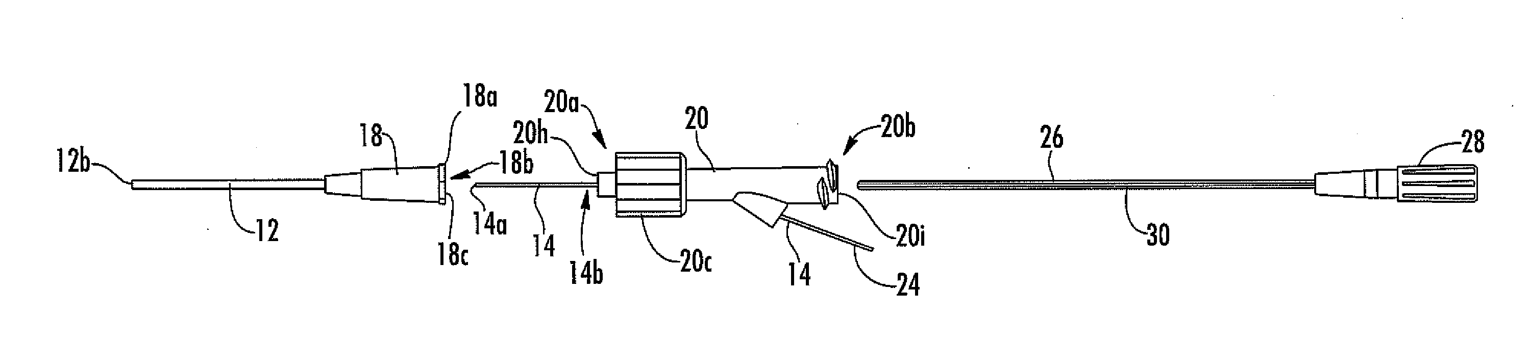
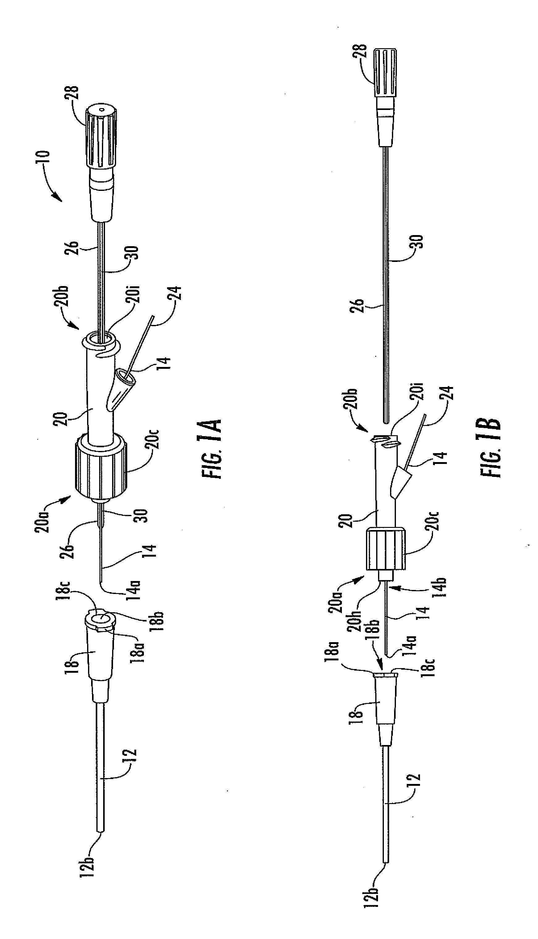
[0029] FIG. 1A is a perspective view of one embodiment of an analyte sensor system, including a vascular access device (e.g., a catheter), a sensor, a fluid connector, and a protective sheath.
[0030] FIG. 1B is a side view of the analyte sensor system of FIG. 1A, showing the protective sheath removed.
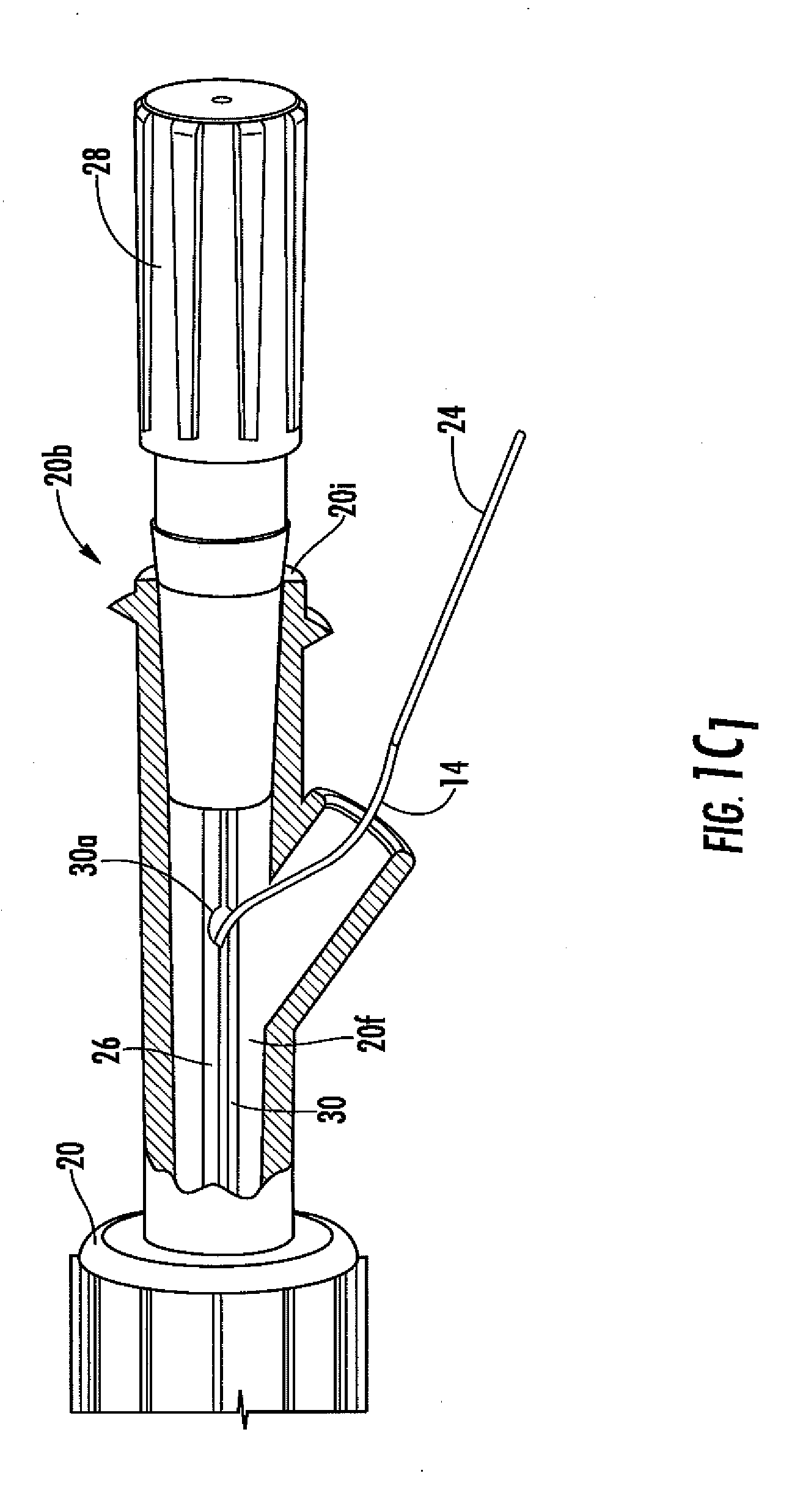
[0031] FIG. 1C.sub.1 is a close-up cut away view of a portion of the analyte sensor system of FIG. 1A.
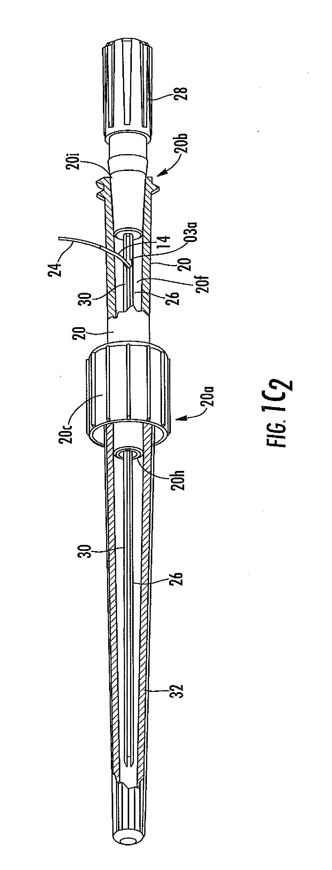
[0032] FIG. 1C.sub.2 is a close-up cut away view of a portion of the analyte sensor system of FIG. 1A.
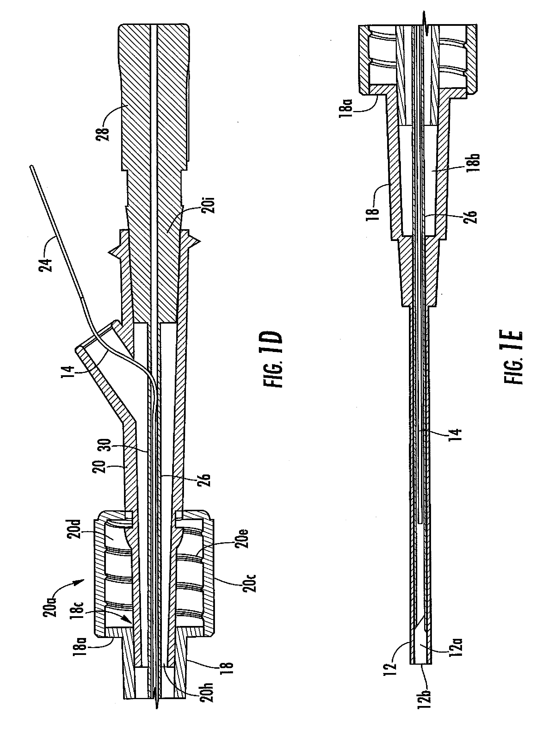
[0033] FIG. 1D is a close-up cut away view of a portion of the analyte sensor system of FIG. 1A.
[0034] FIG. 1E is a close-up cut away view of a portion of the analyte sensor system of FIG. 1A.
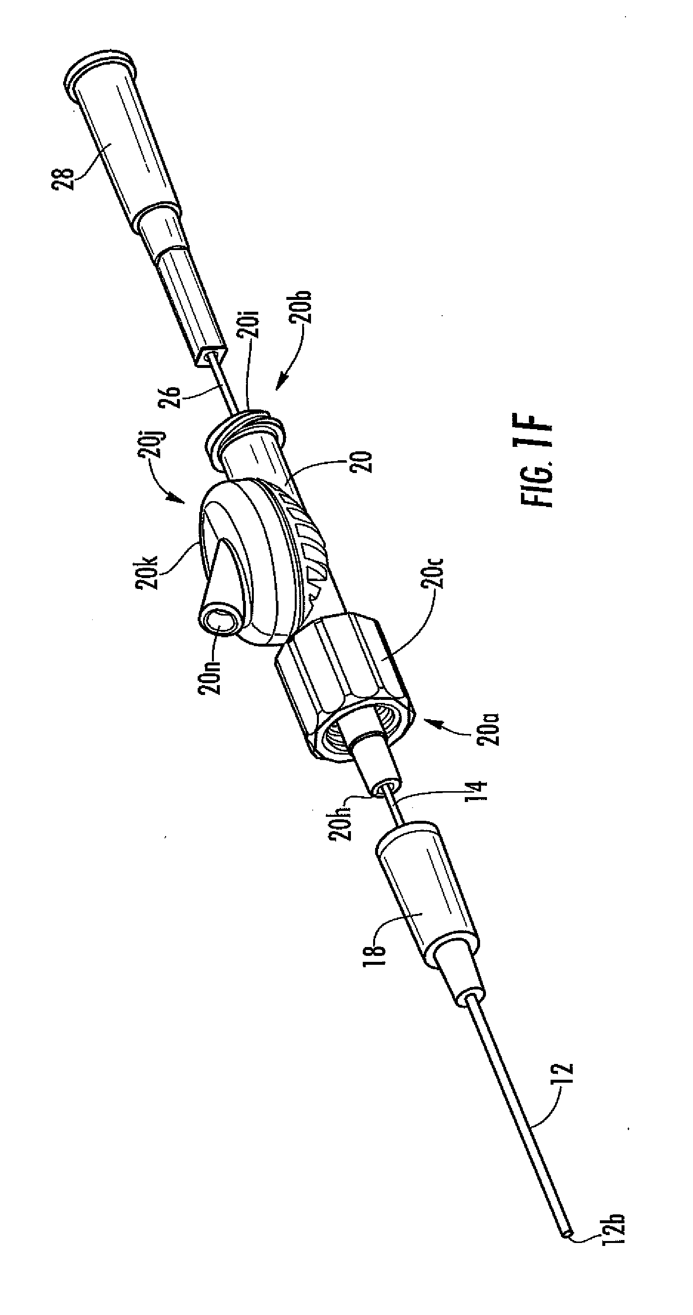
[0035] FIG. 1F is a schematic an analyte sensor system in another embodiment, including a vascular access device, a sensor, a fluid connector, and a protective sheath.
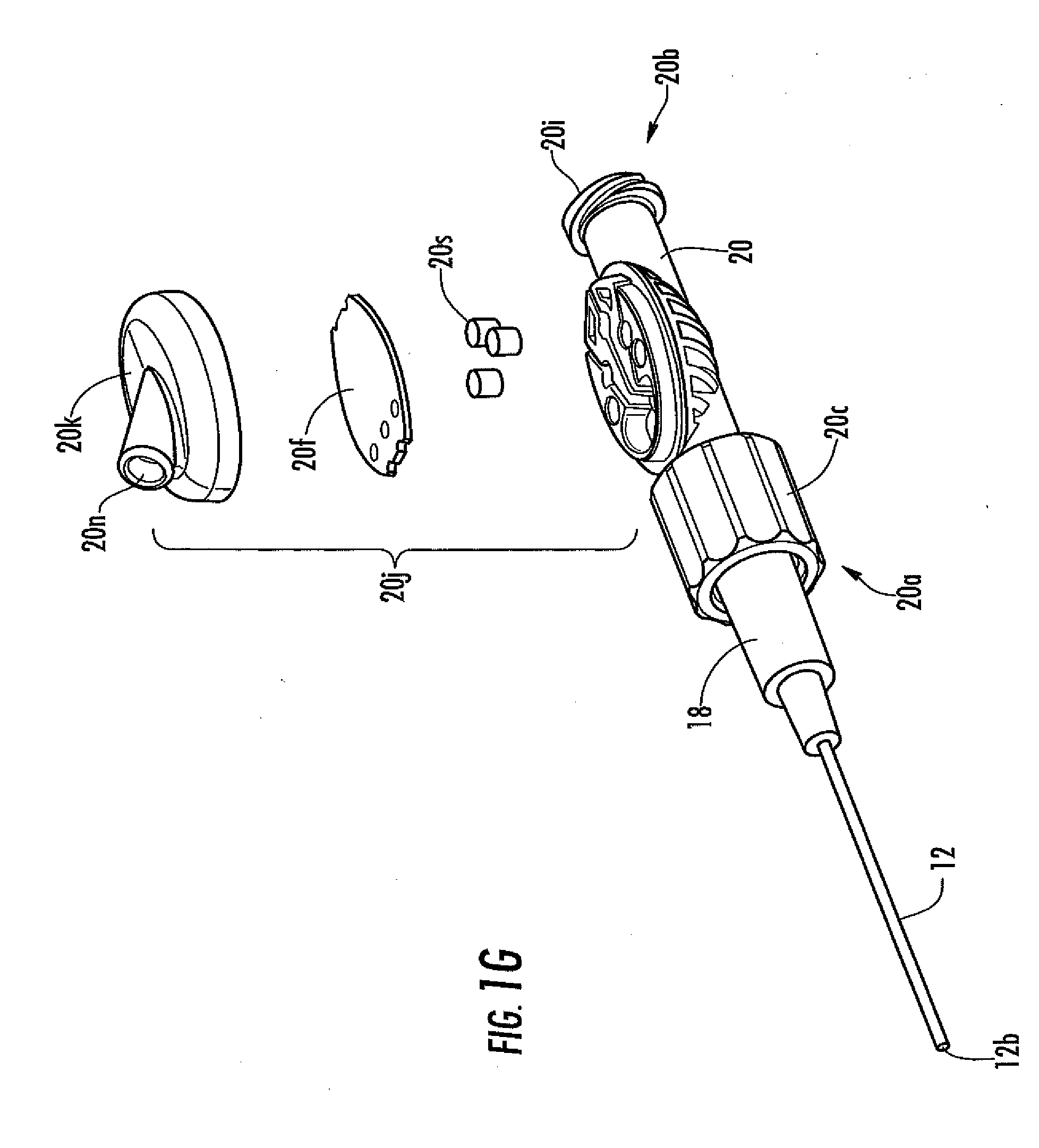
[0036] FIG. 1G is an exploded view of the analyte sensor system of FIG. 1F.
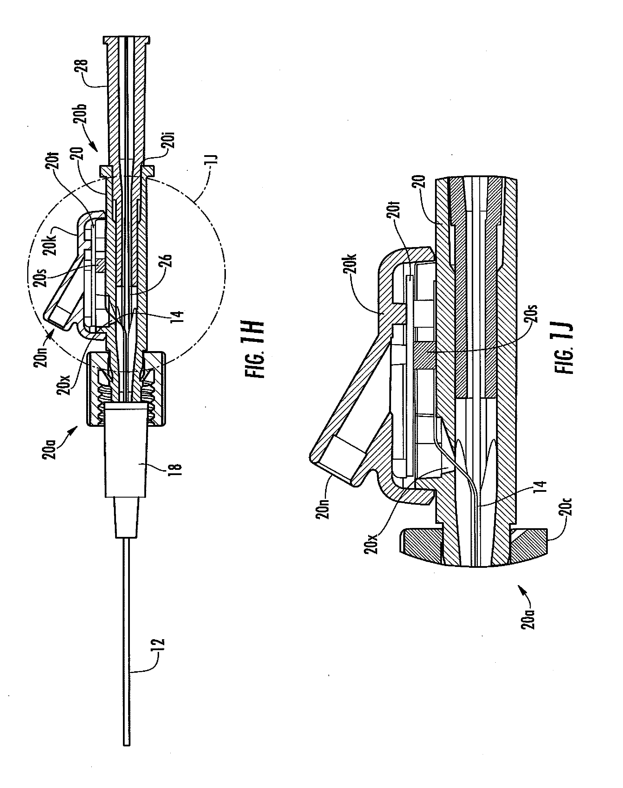
[0037] FIG. 1H is a cut-away view of the analyte sensor system of FIG. 1F.
[0038] FIG. 1J is a magnified view of the encircled portion of the analyte sensor system of FIG. 1H.
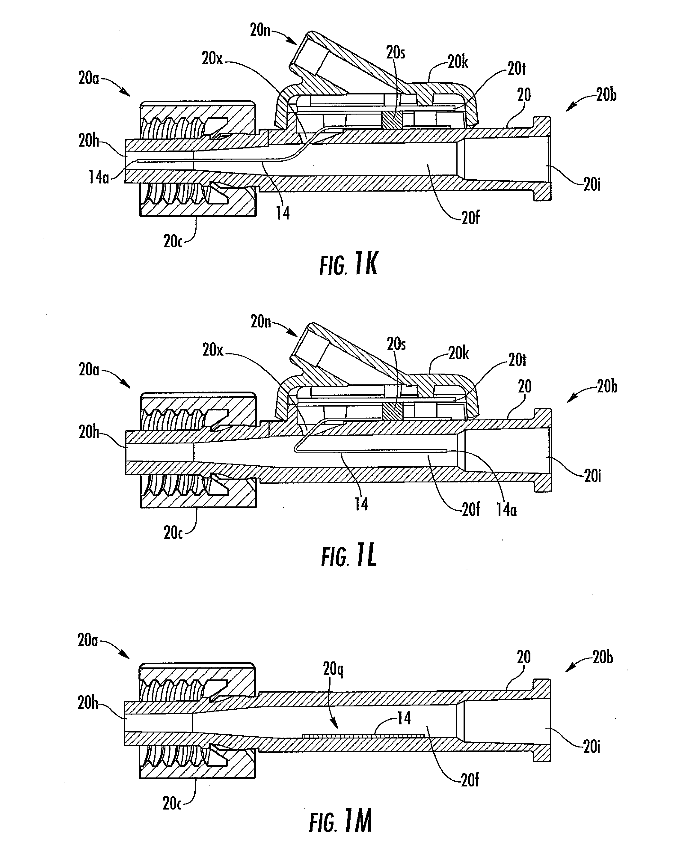
[0039] FIG. 1K is a cut-away view of an analyte sensor system in another embodiment.
[0040] FIG. 1L is a cut-away view of an analyte sensor system in another embodiment.
[0041] FIG. 1M is a cut-away view of an analyte sensor system in another embodiment.
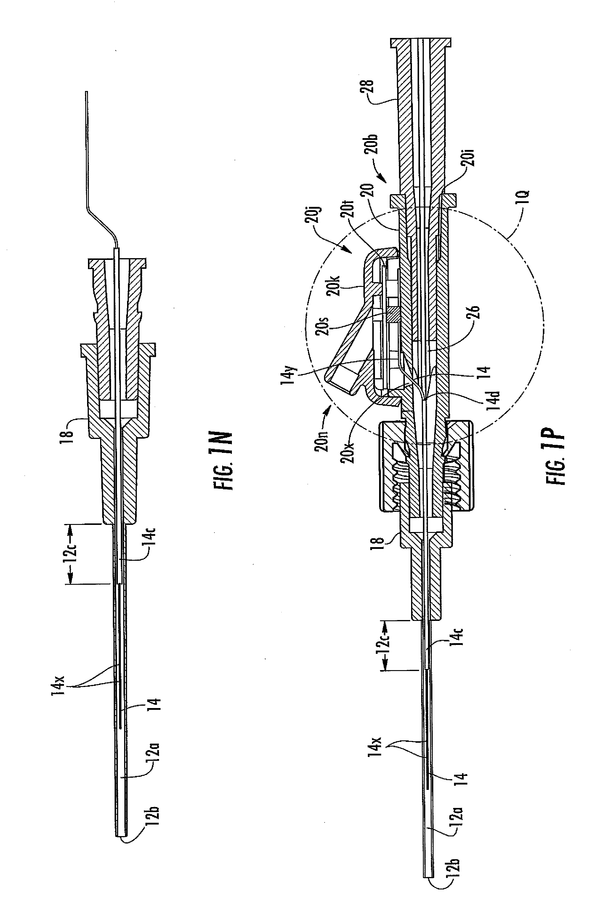
[0042] FIG. 1N is a cut-away view of an analyte sensor system in another embodiment.
[0043] FIG. 1P is cut-away view of an analyte sensor system in another embodiment.
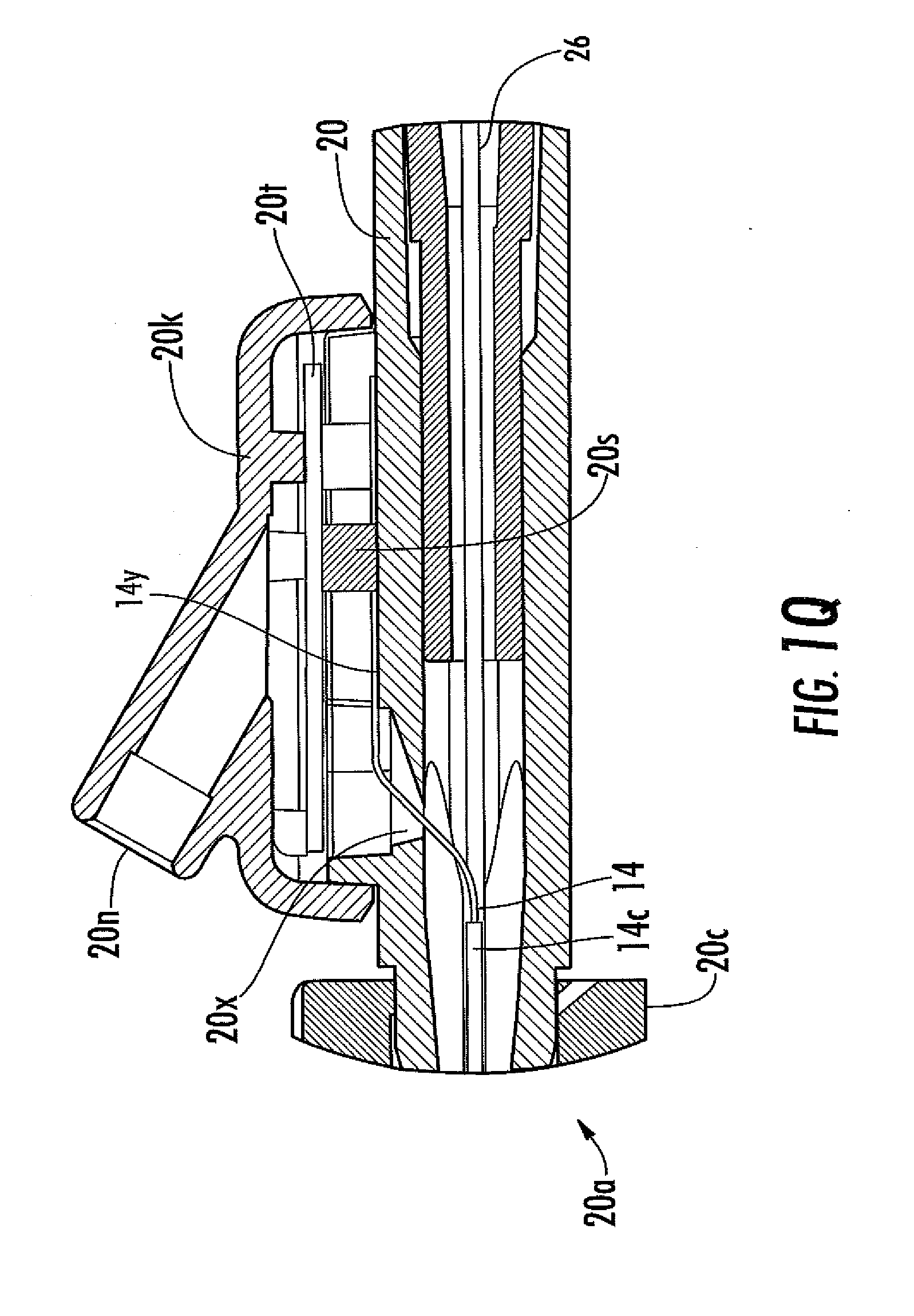
[0044] FIG. 1Q is a magnified view of the encircled portion of the analyte sensor system of FIG. 1P.
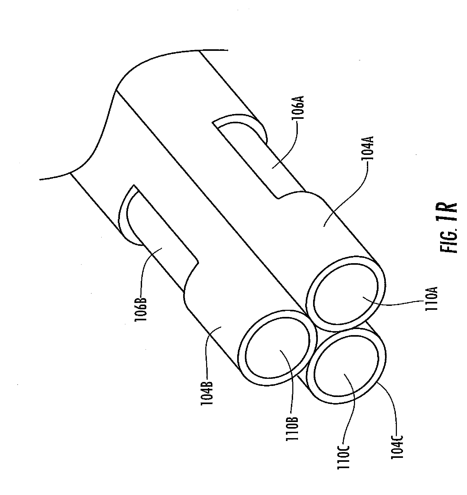
[0045] FIG. 1R is a perspective-view schematic illustrating an in vivo portion of an analyte sensor, in another embodiment.
[0046] FIG. 1S is a perspective-view schematic illustrating an in vivo portion of a dual-electrode analyte sensor, in another embodiment.
[0047] FIG. 2A is a perspective view of another embodiment of the analyte sensor system, including a catheter with a sensor integrally formed thereon.
[0048] FIG. 2B is a perspective view of the analyte sensor system of FIG. 2A.
[0049] FIG. 2C is a close-up view of a portion of the analyte sensor system of FIG. 2A in an alternative configuration of an embodiment having three electrodes disposed on the catheter.
[0050] FIG. 2D is a close-up view of a portion of the analyte sensor system of FIG. 2A in an alternative configuration of an embodiment having three electrodes disposed on the catheter.
[0051] FIG. 2E is a close-up view of a portion of the analyte sensor system of FIG. 2A in an alternative embodiment having two electrodes disposed on the catheter.
[0052] FIG. 2F is a close-up view of a portion of the analyte sensor system of FIG. 2A in an alternative embodiment having one electrode disposed on the catheter.
[0053] FIG. 2G is a cross-section of analyte sensor system in one embodiment, including a plurality of analyte sensors disposed within the connector of a catheter.
[0054] FIG. 2H is a cross-section of analyte sensor system in one embodiment, including a plurality of analyte sensors disposed within a fluid coupler, such as but not limited to a connector, a valve, and a Leur lock.
[0055] FIG. 2I is a cross-section of analyte sensor system of FIG. 2H, taken along line 2I-2I.
[0056] FIG. 2J is a cross-section of analyte sensor system of FIG. 2H, taken along line 2I-2I.
[0057] FIG. 2K is a cross-section of analyte sensor system of FIG. 2H, taken along line 2I-2I.
[0058] FIG. 2L is a cross-section of analyte sensor system of FIG. 2H, taken along line 2I-2I.
[0059] FIG. 2M is a side view schematic of an analyte sensor system in another embodiment, including a plurality of electrodes disposed in a fluid coupler.
[0060] FIG. 2N is a schematic of an analyte sensor system in yet another embodiment, including a fluid coupler having a plurality of lumens, each of which includes an analyte sensor.
[0061] FIG. 2O is a schematic illustrating a method of manufacturing the analyte sensor system of FIG. 2M, in one embodiment.
[0062] FIG. 2P is a schematic illustrating a method of manufacturing the analyte sensor system of FIG. 2M, in another embodiment.
[0063] FIG. 2Q is a side view schematic of an analyte sensor system, including a fluid coupler including a plurality of sensor electrodes disposed therein, in one embodiment.
[0064] FIG. 2R is a cross-sectional schematic of an analyte sensor system, including a fluid coupler including a plurality of sensor electrodes disposed therein, in another embodiment.
[0065] FIG. 2S is a side view schematic of an analyte sensor system, including a fluid coupler including a plurality of sensor electrodes disposed therein, in still another embodiment.
[0066] FIG. 3A is a perspective view of a first portion of one embodiment of an analyte sensor.
[0067] FIG. 3B is a perspective view of a second portion of the analyte sensor of FIG. 3A.
[0068] FIG. 3C is a cross section of the analyte sensor of FIG. 3B, taken on line C-C.
[0069] FIG. 3D is a cross-sectional schematic view of a sensing region of a dual-electrode continuous analyte sensor in one embodiment wherein an active enzyme of an enzyme domain is positioned over the first working electrode but not over the second working electrode.
[0070] FIG. 3E is a perspective view of a dual-electrode continuous analyte sensor in one embodiment.
[0071] FIG. 3F is a cross-sectional schematic illustrating a dual-electrode sensor, in one embodiment, including a physical diffusion barrier.
[0072] FIG. 4A is a schematic of an integrated sensor system.
[0073] FIG. 4B is a block diagram of an integrated sensor system
DETAILED DESCRIPTION
[0074] The following description and examples illustrate some exemplary embodiments of the disclosed invention in detail. Those of skill in the art will recognize that there are numerous variations and modifications of this invention that are encompassed by its scope. Accordingly, the description of a certain exemplary embodiment should not be deemed to limit the scope of the invention.
DEFINITIONS
[0075] In order to facilitate an understanding of the various embodiments, a number of terms are defined below.
[0076] The term "analyte" as used herein is a broad term, and is to be given its ordinary and customary meaning to a person of ordinary skill in the art (and is not to be limited to a special or customized meaning), and refers without limitation to a substance or chemical constituent in a biological sample (e.g., bodily fluids, including, blood, serum, plasma, interstitial fluid, cerebral spinal fluid, lymph fluid, ocular fluid, saliva, oral fluid, urine, excretions or exudates).
[0077] The term "antegrade" as used herein is a broad term, and is to be given its ordinary and customary meaning to a person of ordinary skill in the art (and are not to be limited to a special or customized meaning), and refers without limitation to orientation (e.g., of a catheter) with the direction of blood flow.
[0078] The term "catheter" as used herein is a broad term, and is to be given its ordinary and customary meaning to a person of ordinary skill in the art (and are not to be limited to a special or customized meaning), and refers without limitation to a tube that can be inserted into a host's body (e.g., cavity, duct or vessel). In some circumstances, catheters allow drainage or injection of fluids or access by medical instruments or devices. In some embodiments, a catheter is a thin, flexible tube (e.g., a "soft" catheter). In alternative embodiments, the catheter can be a larger, solid tube (e.g., a "hard" catheter). The term "cannula" is interchangeable with the term "catheter" herein.
[0079] The term "coaxial" as used herein is a broad term, and is to be given its ordinary and customary meaning to a person of ordinary skill in the art (and it is not to be limited to a special or customized meaning), and refers without limitation to having a common axis, having coincident axes or mounted on concentric shafts.
[0080] The terms "coupling" and "operatively coupling" as used herein are broad terms, and are to be given their ordinary and customary meanings to a person of ordinary skill in the art (and are not to be limited to a special or customized meaning), and refer without limitation to a joining or linking together of two or more things, such as two parts of a device or two devices, such that the things can function together. In one example, two containers can be operatively coupled by tubing, such that fluid can flow from one container to another. Coupling does not imply a physical connection. For example, a transmitter and a receiver can be operatively coupled by radio frequency (RF) transmission/communication.
[0081] The terms "electronic connection," "electrical connection," "electrical contact" as used herein are broad terms, and are to be given their ordinary and customary meaning to a person of ordinary skill in the art (and is not to be limited to a special or customized meaning), and refer without limitation to any connection between two electrical conductors known to those in the art. In one embodiment, electrodes are in electrical connection with the electronic circuitry of a device.
[0082] The terms "electronics" and "sensor electronics" as used herein are broad terms, and are to be given their ordinary and customary meaning to a person of ordinary skill in the art (and are not to be limited to a special or customized meaning), and refer without limitation to electronics operatively coupled to the sensor and configured to measure, process, receive, and/or transmit data associated with a sensor. In some embodiments, the electronics include at least a potentiostat that provides a bias to the electrodes and measures a current to provide the raw data signal. The electronics are configured to calculate at least one analyte sensor data point. For example, the electronics can include a potentiostat, A/D converter, RAM, ROM, and/or transmitter. In some embodiments, the potentiostat converts the raw data (e.g., raw counts) collected from the sensor and converts it to a value familiar to the host and/or medical personnel. For example, the raw counts from a glucose sensor can be converted to milligrams of glucose per deciliter of blood (e.g., mg/dl). In some embodiments, the sensor electronics include a transmitter that transmits the signals from the potentiostat to a receiver (e.g., a remote analyzer, such as but not limited to a remote analyzer unit), where additional data analysis and glucose concentration determination can occur.
[0083] The term "ex vivo portion" as used herein is a broad term, and is to be given its ordinary and customary meaning to a person of ordinary skill in the art (and is not to be limited to a special or customized meaning), and refers without limitation to a portion of a device (for example, a sensor) adapted to remain and/or exist outside of a living body of a host.
[0084] The term "fluid communication" as used herein is a broad term, and is to be given its ordinary and customary meaning to a person of ordinary skill in the art (and are not to be limited to a special or customized meaning), and refers without limitation to two or more components (e.g., things such as parts of a body or parts of a device) functionally linked such that fluid can move from one component to another. These terms do not imply directionality.
[0085] The term "helix" as used herein is a broad term, and is to be given its ordinary and customary meaning to a person of ordinary skill in the art (and it is not to be limited to a special or customized meaning), and refers without limitation to a spiral or coil, or something in the form of a spiral or coil (e.g. a corkscrew or a coiled spring). In one example, a helix is a mathematical curve that lies on a cylinder or cone and makes a constant angle with the straight lines lying in the cylinder or cone. A "double helix" is a pair of parallel helices intertwined about a common axis, such as but not limited to that in the structure of DNA.
[0086] The term "indwell" as used herein is a broad term, and is to be given its ordinary and customary meaning to a person of ordinary skill in the art (and are not to be limited to a special or customized meaning), and refers without limitation to reside within a host's body. Some medical devices can indwell within a host's body for various lengths of time, depending upon the purpose of the medical device, such as but not limited to a few hours, days, or weeks, to months, years, or even the host's entire lifetime. In one exemplary embodiment, an arterial catheter may indwell within the host's artery for a few hours, days, a week, or longer, such as but not limited to the host's perioperative period (e.g., from the time the host is admitted to the hospital to the time he is discharged).
[0087] The terms "insulative properties," "electrical insulator" and "insulator" as used herein are broad terms, and are to be given their ordinary and customary meaning to a person of ordinary skill in the art (and is not to be limited to a special or customized meaning) and refers without limitation to the tendency of materials that lack mobile charges to prevent movement of electrical charges between two points. In one exemplary embodiment, an electrically insulative material may be placed between two electrically conductive materials, to prevent movement of electricity between the two electrically conductive materials. In some embodiments, the terms refer to a sufficient amount of insulative property (e.g., of a material) to provide a necessary function (electrical insulation). The terms "insulator" and "non-conductive material" can be used interchangeably herein.
[0088] The terms "integral," "integrally," "integrally formed," integrally incorporated," "unitary" and "composite" as used herein are broad terms, and are to be given their ordinary and customary meaning to a person of ordinary skill in the art (and they are not to be limited to a special or customized meaning), and refer without limitation to the condition of being composed of essential parts or elements that together make a whole. The parts are essential for completeness of the whole. In one exemplary embodiment, at least a portion (e.g., the in vivo portion) of the sensor is formed from at least one platinum wire at least partially covered with an insulative coating, which is at least partially helically wound with at least one additional wire, the exposed electroactive portions of which are covered by a membrane system (see description of FIG. 1B or 9B); in this exemplary embodiment, each element of the sensor is formed as an integral part of the sensor (e.g., both functionally and structurally).
[0089] The term "in vivo portion" as used herein is a broad term, and is to be given its ordinary and customary meaning to a person of ordinary skill in the art (and is not to be limited to a special or customized meaning), and refers without limitation to a portion of a device (for example, a sensor) adapted for insertion into and/or existence within a living body of a host.
[0090] The terms "membrane" and "membrane system" as used herein are broad terms, and are to be given their ordinary and customary meaning to a person of ordinary skill in the art (and are not to be limited to a special or customized meaning), and refer without limitation to a permeable or semi-permeable membrane that can be comprised of one or more domains and is typically constructed of materials of one or more microns in thickness, which is permeable to oxygen and to an analyte, e.g., glucose or another analyte. In one example, the membrane system includes an immobilized glucose oxidase enzyme, which enables a reaction to occur between glucose and oxygen whereby a concentration of glucose can be measured.
[0091] The term "non-enzymatic" as used herein is a broad term, and is to be given their ordinary and customary meaning to a person of ordinary skill in the art (and it is not to be limited to a special or customized meaning), and refers without limitation to a lack of enzyme activity. In some embodiments, a "non-enzymatic" membrane portion contains no enzyme; while in other embodiments, the "non-enzymatic" membrane portion contains inactive enzyme. In some embodiments, an enzyme solution containing inactive enzyme or no enzyme is applied.
[0092] The terms "operatively connected," "operatively linked," "operably connected," and "operably linked" as used herein are broad terms, and are to be given their ordinary and customary meaning to a person of ordinary skill in the art (and are not to be limited to a special or customized meaning), and refer without limitation to one or more components linked to one or more other components. The terms can refer to a mechanical connection, an electrical connection, or any connection that allows transmission of signals between the components. For example, one or more electrodes can be used to detect the amount of analyte in a sample and to convert that information into a signal; the signal can then be transmitted to a circuit. In such an example, the electrode is "operably linked" to the electronic circuitry. The terms include wired and wireless connections.
[0093] The term "potentiostat" as used herein is a broad term, and is to be given its ordinary and customary meaning to a person of ordinary skill in the art (and is not to be limited to a special or customized meaning), and refers without limitation to an electronic instrument that controls the electrical potential between the working and reference electrodes at one or more preset values. Typically, a potentiostat works to keep the potential constant by noticing changes in the resistance of the system and compensating inversely with a change in the current. As a result, a change to a higher resistance would cause the current to decrease to keep the voltage constant in the system. In some embodiments, a potentiostat forces whatever current is necessary to flow between the working and counter electrodes to keep the desired potential, as long as the needed cell voltage and current do not exceed the compliance limits of the potentiostat.
[0094] The terms "processor module" and "microprocessor" as used herein are broad terms, and are to be given their ordinary and customary meaning to a person of ordinary skill in the art (and are not to be limited to a special or customized meaning), and refer without limitation to a computer system, state machine, processor, and the like designed to perform arithmetic or logic operations using logic circuitry that responds to and processes the basic instructions that drive a computer.
[0095] The term "regulator" or "flow control device," as used herein are broad terms, and are to be given their ordinary and customary meaning to a person of ordinary skill in the art (and are not to be limited to a special or customized meaning), and refer without limitation to a device that regulates the flow of a fluid or gas, for example, a valve or a pump.
[0096] The term "sensing region" as used herein is a broad term, and is to be given its ordinary and customary meaning to a person of ordinary skill in the art (and is not to be limited to a special or customized meaning), and refers without limitation to the region of a monitoring device responsible for the detection of a particular analyte.
[0097] The terms "sensor" and "sensor system" as used herein are broad terms, and are to be given their ordinary and customary meaning to a person of ordinary skill in the art (and are not to be limited to a special or customized meaning), and refer without limitation to a device, component, or region of a device by which an analyte can be quantified.
[0098] The term "sheath" as used herein is a broad term, and is to be given its ordinary and customary meaning to a person of ordinary skill in the art (and are not to be limited to a special or customized meaning), and refers without limitation to a covering or supporting structure that fits closely around something, for example, in the way that a sheath covers a blade. In one exemplary embodiment, a sheath is a slender, flexible, polymer tube that covers and supports a wire-type sensor prior to and during insertion of the sensor into a catheter.
[0099] The term "slot" as used herein is a broad term, and is to be given its ordinary and customary meaning to a person of ordinary skill in the art (and are not to be limited to a special or customized meaning), and refers without limitation to a relatively narrow opening.
[0100] The terms "substantial" and "substantially" as used herein are broad terms, and are to be given their ordinary and customary meaning to a person of ordinary skill in the art (and are not to be limited to a special or customized meaning), and refer without limitation to a sufficient amount that provides a desired function. For example, an amount greater than 50 percent, an amount greater than 60 percent, an amount greater than 70 percent, an amount greater than 80 percent, or an amount greater than 90 percent.
[0101] The term "valve" as used herein is a broad term, and is to be given its ordinary and customary meaning to a person of ordinary skill in the art (and are not to be limited to a special or customized meaning), and refers without limitation to a device that regulates the flow of substances (either gases, fluidized solids, slurries, or liquids), for example, by opening, closing, or partially obstructing a passageway through which the substance flows. In general, a valve allows no flow, free flow and/or gravity flow and/or metered flow through movement of the valve between one or more discreet positions.
[0102] The term "vascular access device" as used herein is a broad term, and is to be given its ordinary and customary meaning to a person of ordinary skill in the art (and are not to be limited to a special or customized meaning), and refers without limitation to any device that is in communication with the vascular system of a host. Vascular access devices include but are not limited to catheters, shunts, blood withdrawal devices, connectors, valves, tubing and the like.
[0103] The in vivo continuous analyte monitoring system of the various embodiments can be used in clinical settings, such as in the hospital, the doctor's office, long-term nursing facilities, or even in the home. The present device can be used in any setting in which frequent or continuous analyte monitoring is desirable. For example, in the ICU, hosts are often recovering from serious illness, disease, or surgery, and control of host glucose levels is important for host recovery. For example, use of a continuous glucose sensor as described in the some embodiments allows tight control of host glucose concentration and improved host care, while reducing hypoglycemic episodes and reducing the ICU staff work load. For example, the system can be used for the entire hospital stay or for only a part of the hospital stay.
[0104] In addition to use in the circulatory system, the analyte sensor of the various embodiments can be used in other body locations. In some embodiments, the sensor is used subcutaneously. In another embodiment, the sensor can be used intracranially. In another embodiment, the sensor can be used within the spinal compartment, such as but not limited to the epidural space. In some embodiments, the sensor of the various embodiments can be used with or without a catheter.
Applications/Uses
[0105] One aspect of the various embodiments provides a system for in vivo continuous analyte monitoring (e.g., albumin, alkaline phosphatase, alanine transaminase, aspartate aminotransferase, bilirubin, blood urea nitrogen, calcium, CO.sub.2, chloride, creatinine, glucose, gamma-glutamyl transpeptidase, hematocrit, lactate, lactate dehydrogenase, magnesium, oxygen, pH, phosphorus, potassium, sodium, total protein, uric acid, a metabolic marker, a drug, various minerals, various metabolites, and the like) that can be operatively coupled to a catheter to measure analyte concentration within the host's blood stream. In still other embodiments, the analyte sensor is disposed entirely within and/or on the fluid coupler, which is in turn fluidly coupled to a catheter or other vascular access device, as described elsewhere herein.
[0106] The following U.S. patent applications are related to the current application and the contents of these applications are herein incorporated by reference: U.S. Patent Publication No. 2009-0137886, filed Nov. 7, 2008, titled Analyte Sensor; U.S. Patent Publication No. 2009-0137887, filed Nov. 7, 2008, titled Analyte Sensor; U.S. Patent Publication No. 2009-0131777, filed Nov. 7, 2008, titled Analyte Sensor; U.S. Patent Publication No. 2009-0131768, filed Nov. 7, 2008, titled Analyte Sensor; and US 2009-0131769, filed Nov. 7, 2008, titled Analyte Sensor.
[0107] FIGS. 1A to 1J illustrate two embodiments of an exemplary analyte sensor system 10 for measuring an analyte, as described elsewhere herein, that includes a catheter 12 configured to be inserted or pre-inserted into a host's blood stream. In clinical settings, catheters are often inserted into hosts to allow direct access to the circulatory system without frequent needle insertion (e.g., venipuncture). Suitable catheters can be sized as is known and appreciated by one skilled in the art, such as but not limited to from about 1 French (0.33 mm) or less to about 30 French (10 mm) or more; and can be, for example, 2, 3, 4, 5, 6, 7, 8, 9, 10, 11, 12, 13, 14, 15, 16, 17, 18, 19, or 20 French (3 French is equivalent to about 1 mm) and/or from about 33 gauge or less to about 16 gauge or more, for example, 33, 32, 31, 30, 29, 28, 27, 26, 25, 24, 23, 22, 21, 20, 19, 18, 17, or 16 gauge. Additionally, the catheter can be shorter or longer, for example 0.75, 1.0, 1.25, 1.5, 1.75, 2.0 inches in length or longer. In some embodiments, the catheter is a venous catheter. In other embodiments, the catheter is configured for insertion into a peripheral or a central artery. In some embodiments, the catheter is configured to extend from a peripheral artery to a central portion of the host's circulatory system, such as but not limited to the heart. In still other embodiments, the catheter is configured for insertion into neonatal or other pediatric hosts (e.g., 22-24 gauge or smaller). The catheter can be manufactured of any medical grade material known in the art, such as but not limited to polymers and glass as described herein. A catheter can include a single lumen or multiple lumens. A catheter can include one or more perforations, to allow the passage of host fluid through the lumen of the catheter.
[0108] The terms "inserted" or "pre-inserted" as used herein are broad terms, and are to be given their ordinary and customary meaning to a person of ordinary skill in the art (and are not to be limited to a special or customized meaning), and refer without limitation to insertion of one thing into another thing. For example, a catheter can be inserted into a host's blood stream. In some embodiments, a catheter is "pre-inserted," meaning inserted before another action is taken (e.g., insertion of a catheter into a host's blood stream prior to insertion of a sensor into the catheter). In some exemplary embodiments, a sensor is coupled to a pre-inserted catheter, namely, one that has been previously inserted (or pre-inserted) into the host's circulatory system. Alternatively, the sensor and the catheter can be configured to be inserted together and/or the sensor can be integrally formed with the catheter.
[0109] Referring now to FIGS. 1A to 1J, various embodiments of an analyte sensor system 10 are show. The system 10, in some embodiments includes catheter 12, which is a thin, flexible tube having a lumen 12a, such as is known in the art. In some embodiments, the catheter can be rigid; in other embodiments, the catheter can be custom manufactured to desired specifications (e.g., rigidity, dimensions, etc). The catheter can be a single-lumen catheter or a multi-lumen catheter. In some embodiments, the catheter is a peripheral catheter configured and arranged for insertion into a peripheral vessel (e.g., vein and/or artery) in a host's arm and/or leg. In some embodiments, the catheter is a central catheter, configured and arranged for insertion into a host's central vessel (e.g., internal jugular vein, subclavian vein, femoral vein and/or pulmonary artery). At the catheter's proximal end is a small orifice 12b for fluid connection of the catheter to the blood stream. At the catheter's distal end is a connector 18, such as a Leur connector or other fluid connector known in the art.
[0110] The illustrations of FIGS. 1A to 1J show two exemplary embodiments of the connector 18 including a flange 18a and a duct 18b. In the exemplary embodiment, the flange 18a is configured to enable connection of the catheter to other medical equipment (e.g., saline bag, pressure transducer, blood chemistry device, and the like) or capping (e.g., with a bung and the like). Although one exemplary connector is shown, one skilled in the art appreciates a variety of standard or custom made connectors suitable for use with the various embodiments. The duct 18b is in fluid communication with the catheter lumen and terminates in a connector orifice 18c.
[0111] In some embodiments, the catheter is inserted into the host's blood stream, such as into a vein or artery by any useful method known in the art. Generally, prior to and during insertion, the catheter is supported by a hollow needle or trochar (not shown). For example, the supported catheter can be inserted into a peripheral vein or artery, such as in the host's arm, leg, hand, or foot. Typically, the supporting needle is removed (e.g., pulled out of the connector) and the catheter is connected (e.g., via the connector 18) to IV tubing and a saline drip, for example. However, in one embodiment, the catheter is configured to operatively couple to medical equipment, such as but not limited to a sensor system of the various embodiments. Additionally and/or alternatively, the catheter can be configured to operatively couple to another medical device, such as a pressure transducer, for measurement of the host's blood pressure.
[0112] In some embodiments, the catheter and the analyte sensor are configured to indwell within the host's blood stream in vivo. An indwelling medical device, such as a catheter or implant, is disposed within a portion of the body for a period of time, from a few minutes or hours to a few days, months, or even years. An indwelling catheter is typically inserted within a host's vein or artery for a period of time, often 2 or more days, a month, or even a few months. In some embodiments, the catheter can indwell in a host's artery or vein for the length of a perioperative period (e.g., the entire hospital stay) or for shorter or longer periods. In some embodiments, the use of an indwelling catheter permits continuous access of an analyte sensor to a blood stream while simultaneously allowing continuous access to the host's blood stream for other purposes, for example, the administration of therapeutics (e.g., fluids, drugs, etc.), measurement of physiologic properties (e.g., blood pressure), fluid removal, and the like.
[0113] Referring again to FIGS. 1A to 1J, the system 10 also includes an analyte sensor 14 configured to extend through the catheter lumen 12a (see FIG. 1E), out of the catheter orifice 12b and into the host's blood stream by about 0.010 inches to about 1 inch, or shorter or longer lengths. In some embodiments, however, the sensor may not extend out of the catheter, for example, can reside just inside the catheter tip. The sensor can extend through the catheter in any functional manner. In some embodiments, the sensor is configured to be held (e.g., located, disposed) on an inner surface (e.g., the lumenal surface) or outer surface of the catheter. In some embodiments, the sensor is deposited (e.g., formed) on a surface of the catheter. In some embodiments, a sensor is attached to a surface of the catheter, such as by an adhesive and/or welding. In some other embodiments, the sensor is configured to "free float" within the lumen of the catheter. In some embodiments, the sensor resides within the fluid coupler.
[0114] In some embodiments, the sensor 14 is configured to measure the concentration of an analyte (e.g., albumin, alkaline phosphatase, alanine transaminase, aspartate aminotransferase, bilirubin, blood urea nitrogen, calcium, CO.sub.2, chloride, creatinine, glucose, gamma-glutamyl transpeptidase, hematocrit, lactate, lactate dehydrogenase, magnesium, oxygen, pH, phosphorus, potassium, sodium, total protein, uric acid, a metabolic marker, various drugs, various minerals, various metabolites, and the like) within the host's blood stream. In some embodiments, the sensor includes at least one electrode (see, e.g., FIG. 3B), for example a working electrode; however any combination of working electrode(s), reference electrode(s), and/or counter electrode(s) can be implemented as is appreciated by one skilled in the art. For example, in some embodiments, the sensor includes at least two working electrodes, as is described with reference to FIGS. 3D through 3I. In still other embodiments, two or more analyte sensors are in fluid communication with the vascular access device (e.g., disposed within the vascular access device), such that two or more analytes can be monitored simultaneously, and/or sequentially, continuously and/or intermittently, and the like. Preferably, the sensor 14 includes at least one exposed electroactive area (e.g., working electrode), a membrane system (e.g., including an enzyme), a reference electrode (proximal to or remote from the working electrode), and an insulator material. Various systems and methods for design and manufacture of continuous analyte sensors are described in more detail elsewhere herein. In some embodiments, the sensor is a needle-type continuous analyte sensor, configured as disclosed in U.S. Patent Publication No. US-2006-0020192-A1 and U.S. Patent Publication No. US-2006-0036143-A1, both of which are incorporated herein by reference in their entirety. In some embodiments, the sensor is disposed on a planar substrate, configured as disclosed in U.S. Pat. No. 6,175,752, U.S. Pat. No. 6,512,939 and U.S. Pat. No. 7,402,153, each of which are incorporated herein by reference in their entirety. In some embodiments, the sensor is configured to measure glucose concentration. Exemplary sensor configurations are discussed in more detail, elsewhere herein.
[0115] Referring to various embodiments illustrated in FIGS. 1A to 1Q, the sensor 14 has a proximal end 14a and a distal end 14b. The proximal end 14a is also referred to herein as the "sensor tip" or "tip". At its distal end 14b, the sensor 14 is associated with (e.g., connected to, held by, extends through, and the like) a fluid coupler 20 having first and second sides (20a and 20b, respectively). The fluid coupler is configured to mate (via its first side 20a) to the catheter connector 18. In one embodiment, a skirt 20c is located at the fluid coupler's first side and includes an interior surface 20d with threads 20e (see FIGS. 1D and 1E). In this embodiment, the fluid coupler is configured to mate with the connector flange 18a, which is screwed into the fluid coupler via the screw threads. However, in other embodiments, the fluid coupler is configured to mate with the connector using any known mating configuration, for example, a snap-fit, a press-fit, an interference-fit, and the like, and can include a locking mechanism to prevent separation of the connector and fluid coupler. The fluid coupler 20 includes a lumen 20f extending from a first orifice 20h on its first side 20a to a second orifice 20i located on the fluid coupler's second side 20b (FIGS. 1C1 to 1E). When the catheter connector is mated with the fluid coupler, the catheter's lumen 12a is in fluid communication with the fluid coupler's lumen 20f via orifices 18c and 20h.
[0116] FIGS. 1A to 1D, for example, show one embodiment of a fluid coupler 20, namely, a Y-coupler; however, any known coupler configuration can be used, including but not limited to a straight coupler, a T-coupler, a cross-coupler, a custom configured coupler, and the like. In some embodiments, the fluid coupler includes at least one valve (e.g., a septum, a 3-way valve, a stop-cock valve), which can be used for a variety of purposes (e.g., injection of drugs). As another example, FIGS. 1F-1J illustrate a fluid coupler configured for connection of the sensor to sensor electronics via a female electrical connector 20n configured to releasably mate with a male plug on an electronic cable. The fluid coupler can be made of any convenient material, such as but not limited to plastic, glass, metal or combinations thereof and can be configured to withstand known sterilization techniques.
[0117] In some embodiments, the second side 20b of the fluid coupler 20 is configured to be operably connected to IV equipment, another medical device or to be capped, and can use any known mating configuration, for example, a snap-fit, a press-fit, an interference-fit, and the like. In one exemplary embodiment, the second side 20b is configured to mate with a saline drip, for delivery of saline to the host. For example, the saline flows from an elevated bag of sterile saline via tubing, through the fluid coupler, through the catheter and into the host's blood system (e.g., vein or artery). In another embodiment, a syringe can be mated to the fluid coupler, for example, to withdraw blood from the host, via the catheter. Additional connection devices (e.g., a three-way valve) can be operably connected to the fluid coupler, to support additional functionality and connection of various devices, such as but not limited to a blood pressure transducer.
[0118] Referring to the embodiment of FIGS. 1A and 1E, at least a portion of the sensor 14 passes through the fluid coupler 20 (e.g., the fluid coupler lumen 201) and is operatively connected to sensor electronics (not shown) via a hardwire 24. In alternative embodiments however, the sensor electronics can be disposed in part or in whole with the fluid coupler (e.g., integrally with or proximal to) or can be disposed in part or in whole remotely from the fluid coupler (e.g., on a stand or at the bed side). Connections between the sensor and sensor electronics (in part or in whole) can be accomplished using known wired or wireless technology. In one exemplary embodiment, the sensor is hardwired to the electronics located substantially wholly remote from the fluid coupler (e.g., disposed on a stand or near the bedside); one advantage of remote electronics includes enabling a smaller sized fluid coupler design. In another exemplary embodiment, a portion of the sensor electronics, such as a potentiostat, is disposed on the fluid coupler and the remaining electronics (e.g., electronics for receiving, data processing, printing, connection to a nurses' station, etc.) are disposed remotely from the fluid coupler (e.g., on a stand or near the bedside). One advantage of this design can include more reliable electrical connection with the sensor in some circumstances. In this embodiment, the potentiostat can be hardwired directly to the remaining electronics or a transmitter can be disposed on or proximal to the fluid coupler, for remotely connecting the potentiostat to the remaining electronics (e.g., by radio frequency (RF)). In another exemplary embodiment, all of the sensor electronics can be disposed on the fluid coupler. In still another embodiment, the sensor electronics disposed on the fluid coupler include a potentiostat.
[0119] Referring again to FIGS. 1A to 1Q, a protective sheath 26 is configured to cover at least a portion of the sensor 14 during insertion, and includes hub 28 and slot 30. In general, the protective sheath protects and supports the sensor prior to and during insertion into the catheter 12 via the connector 18. The protective sheath can be made of biocompatible polymers known in the art, such as but not limited to polyethylene (PE), polyurethane (PE), polyvinyl chloride (PVC), polycarbonate (PC), nylon, polyamides, polyimide, polytetrafluoroethylene (PTFE), Teflon, nylon and the like. The protective sheath includes a hub 28, for grasping the sheath (e.g., while maintaining sterilization of the sheath). In this embodiment, the hub additionally provides for mating with the second side 20b of the fluid coupler 20, prior to and during sensor insertion into the catheter. In this exemplary embodiment, the slot of the protective sheath is configured to facilitate release of the sensor therefrom. In this embodiment, after the sensor has been inserted into the catheter, the hub is grasped and pulled from the second side of the fluid coupler. This action peels the protective sheath from the sensor (e.g., the sensor slides through the slot as the sheath is removed), leaving the sensor within the catheter. The second side of the fluid coupler can be connected to other medical devices (e.g., a blood pressure monitor) or an IV drip (e.g., a saline drip), or capped. In alternative embodiments, the sheath can fold (e.g., fold back or concertinas) or retract (e.g., telescope) during insertion, to expose the sensor. In other embodiments, the sheath can be configured to tear away from the sensor before, during, or after insertion of the sensor. In still other embodiments, the sheath can include an outlet hole 30a, to allow protrusion of the sensor from the back end of the sheath (e.g., near the hub 28). One skilled in the art will recognize that additional configurations can be used, to separate the sensor 14 from the sheath 26.
[0120] In some embodiments, the sensor includes at least two working electrodes, which can be twisted and/or bundled, such as in a helical and/or coaxial configuration. In some embodiments, the two working electrodes are twisted into a "twisted pair," which can be configured to be inserted into and to extend within a vascular access device, such as a catheter 12 or cannula implanted in a host's vein or artery. In some embodiments, the twisted pair is configured to reside within the lumen 12a of the catheter 12; while in other embodiments, the twisted pair is configured to protrude from the catheter's proximal orifice 12b. In still other embodiments, the twisted pair is configured to intermittently protrude from the catheter's proximal orifice 12b.
[0121] In some embodiments, the sheath 26 can be optional, depending upon the sensor design. For example, the sensor can be inserted into a catheter or other vascular access device with or without the use of a protective sheath). In some embodiments, the sensor can be disposed on the outer surface of a catheter (as described elsewhere herein) or on the inner surface of a catheter; and no sheath is provided. In other embodiments, a multi-lumen catheter can be provided with a sensor already disposed within one of the lumens; wherein the catheter is inserted into the host's vein or artery with the sensor already disposed in one of the lumens. In one exemplary embodiment, the system includes a catheter having multiple lumens, and is configured and arranged to infuse a fluid in a first lumen of the catheter and to draw back a biological sample into a second lumen of the catheter. In a further embodiment, an analyte sensor is located in the second lumen of the catheter. In some embodiments, the system is configured to infuse a fluid into the second lumen, such as to reinfuse a drawn back sample into the host and/or to wash the sensor. In some embodiments, a flow control device is configured and arranged for infusion of at least two solutions, such as via a multi-lumen catheter, and includes at least two valves.
[0122] In some alternative embodiments, an analyte sensor is integrally formed on a catheter. In various embodiments, the catheter can be placed into a host's vein or artery in the usual way a catheter is inserted, as is known by one skilled in the art, and the host's analyte concentration measured substantially continuously. In some embodiments, the sensor system can be coupled to one or more additional devices, such as a saline bag, an automated blood pressure monitor, a blood chemistry monitor device, and the like. In one exemplary embodiment, the integrally formed analyte sensor is a glucose sensor.
[0123] FIGS. 1F through 1L, 1P and 1Q illustrate various embodiments of the sensor system, wherein the fluid coupler 20 includes a housing 20j configured and arranged for electrical connection of the analyte sensor 14 to at least some system electronics, such as an electronic cable (not shown). The housing 20j includes a housing cover 20k and an electrical connector 20n. While a female socket (e.g., configured to releasably mate with a male plug) is shown, any electrical connection known in the art can be used, as is appreciate by one skilled in the art.
[0124] FIGS. 1G-1H are exploded and cut-away views, respectively, of the embodiment shown in FIG. 1F. The encircled portion of FIG. 1H is shown in FIG. 1J and illustrates the configuration of the distal portion of the analyte sensor 14 within the housing 20j, in this embodiment. FIGS. 1K and 1L also illustrate alternate embodiments of the system. Referring now to the various embodiments illustrated in FIGS. 1G-1J, 1K-1L, and 1P-1Q, the analyte sensor can be configured and arranged to detect one or more analytes, as described elsewhere herein. Between the fluid coupler 20 and the housing 20j is disposed a seal 20x configured to couple the fluid couple to the housing. The seal 20x is also configured to define a conduit for at least one sensor and/or conductive lead, wire or trace of the one or more sensors from the fluid coupler 20 to the housing 20j. Further, the seal is configured to prevent flow of fluid from the fluid coupler 20 to the housing 20j thereby protecting the electrical components housed within the housing from contact with fluid and potential damage and/or malfunction. In alternate embodiments, the seal 20x is formed around a peripheral of the sensor 14 at or proximate the intersection of the fluid coupler 20 and the housing 20j. In others, the connection between the fluid coupler 20 and the housing 20j forms the seal 20x. In yet others the seal 20x is part of the fluid coupler 20, and in others, the seal is part of the housing 20j.
[0125] The proximal portion (ex vivo portion, which can be referred to as a conductive wire, lead or trace) of the analyte sensor 14 is configured and arranged for electrical connection with the sensor electronics via one or more elastomeric contacts or other connectors 20s and a printed circuit board (PCB) 20t disposed within the housing. In this embodiment, the connection is a solderless connection. However, in some embodiments, electrical connection of the electrodes to the electronics can be made by other means, for example, wires, contact pads, pogo pins, domed metallic contacts, cantilevered fingers, metallic springs, soldering and/or conductive adhesive.
[0126] In the embodiment shown in FIGS. 1G-1J, an elastomeric contact or other connector 20s, which can be manufactured of an conductive elastomeric material such as a carbon black elastomer, makes an electrical connection between each of the sensor's electrodes (e.g., working (plus or minus enzyme), counter and/or reference electrodes) and the PCB. For example, as shown in FIG. 1J, the electrodes make contact with the elastomeric contacts, and the elastomeric contacts make contact with the PCB. The PCB is configured and arranged to make an electrical connection with at least some of the system electronics, such as but not limited to by electrical connector 20n. Conductive elastomers are advantageously employed because their resilient properties create a natural compression against mutually engaging contacts, forming a secure press fit therewith. In some embodiments, conductive elastomers can be molded in such a way that pressing the elastomer against an adjacent contact performs a wiping action on the surface of the contact, thereby creating a cleaning action during initial connection. Additionally, in some embodiments, the sensor 14 extends through the connectors 20s wherein the sensor is electrically and mechanically secured by the relaxation of elastomer around the sensor.
[0127] In an alternative embodiment, a conductive, stiff plastic forms the contacts, which are shaped to comply upon application of pressure (for example, a leaf-spring shape). Contacts of such a configuration can be used instead of a metallic spring, for example, and advantageously avoid the need for crimping or soldering through compliant materials; additionally, a wiping action can be incorporated into the design to remove contaminants from the surfaces during connection. Non-metallic contacts can be advantageous because of their seamless manufacturability, robustness to thermal compression, non-corrosive surfaces, and native resistance to electrostatic discharge (ESD) damage due to their higher-than-metal resistance.
[0128] While in this embodiment (e.g., shown in FIGS. 1H and 1J), the proximal portion (e.g., part of the ex vivo portion, also referred to herein as the first portion) of each electrode physically contacts the bottom of (e.g., beneath) an elastomeric connector, the electrodes can make an electrical connection with elastomeric contacts by a variety of other ways. For example, in some embodiments, one or more of the electrodes can contact the top and/or side of the elastomeric contacts (e.g., above and/or beside). In still other embodiments, an electrode can intersect an elastomeric contact (e.g., pass through at least a portion of the elastomeric contact). In yet another embodiment, the proximal portion of an electrode can be wrapped around an elastomeric contact. Additional configurations are considered in the various embodiments. For example, the different configurations can be combined, such as for example, with one electrode touching the bottom of a first elastomeric contact, a second electrode touching the top of a second elastomeric contact, and a third electrode passing through yet another elastomer contact.
[0129] In some embodiments, the interior of the housing is configured to guide placement of the electrodes for contact with the elastomeric contacts, which can simplify manufacturing and ensure formation of a good electrical contact between each electrode and its corresponding elastomeric contact. For example, in the embodiment shown in FIGS. 1H and 1J, pathways (e.g., recessed) are provided, to guide the placement of the electrode wires within the housing, and wells or cups are provided to receive the elastomeric contacts. For example, in FIG. 1G, the proximal portion of each of the sensor's electrodes are received into one of the three pathways provided, a connector 20s, such as an elastomeric contact is placed in each of the three wells, and then the PCB 20t is placed on top of the elastomeric contacts. Then, the housing cover 20k, which, in some embodiments, includes an electrical connector 20n, is applied to close the housing.
[0130] FIG. 1K illustrates another embodiment of the analyte sensor 14 incorporated into a fluid coupler 20. In this embodiment, the sensor is configured such that it extends at least a portion of the length of the lumen 20f of the fluid coupler, but does not extend out of the fluid coupler itself (e.g., past the fluid coupler's first orifice 20h). When the fluid coupler of this embodiment is fluidly coupled to an implanted catheter, the first side 20a of the fluid coupler releasably mates with the catheter hub, such that a portion of the fluid coupler's first orifice 20h is located within a portion of the catheter hub's duct or lumen (e.g., 18b, see FIGS. 1D-1E). Accordingly, in this embodiment, the sensor tip 14a can be located within the catheter hub's duct or lumen. Advantageously, this embodiment simplifies device installation as no insertion of the sensor into a catheter is required. Additionally, sensor performance is maintained because the sensor is protected by the fluid coupler's hard structure during connection of the fluid coupler to the catheter (e.g., the sensor cannot be accidentally touched, bent or flexed during installation).
[0131] FIG. 1L illustrated an embodiment similar to that of FIG. 1K, except that at least a portion of the sensor 14 extends toward the fluid coupler's 20 second side 20b. In some embodiments, the sensor tip extends to the fluid coupler's second orifice 20i, but not there past. In other embodiments, the sensor is configured to extend into connected tubing. Accordingly, in this embodiment, the sensor's electroactive surface(s) can be located at any point along the length of the fluid coupler's lumen 20f.
[0132] FIG. 1M illustrates yet another embodiment of an analyte sensor incorporated into a fluid coupler 20. In this embodiment, at least one analyte sensor 14 is located on a support 20q that is located on the lumenal surface of the fluid coupler. In some embodiments, the support, including the at least one analyte sensor located thereon, is inserted into the fluid coupler via an orifice (e.g., 20i). In other embodiments, the fluid coupler includes a port (e.g., an orifice, hole or opening, not shown) configured and arranged to receive the support (e.g., the port and the support are configured to mate with each other), such as via insertion through the wall of the fluid coupler. In some embodiments, the at least one analyte sensor comprises two or more analyte sensors, wherein the analyte sensors are configured to detect one or more analytes. In some embodiments, the at least one analyte sensor comprises 3, 4, 5, 6, 7, 8, 9, 10 or more analytes sensors. In some embodiments, the at least one analyte sensor comprises a plurality of micro-fabricated sensors, such as but not limited to a sensor array. The sensor(s) can be applied to and/or deposited on the support using any method known in the art, such as but not limited to thin and/or thin film techniques, printing, plating, and the like. In some embodiments, an analyte sensor is configured to intersect the support, such as described with reference to FIGS. 2M-2Q. In some embodiments, the sensor (e.g., working electrode) is substantially flush with the support, similar to the manner of some glucose test strips that have electrodes printed on a planar support using thin and/or thick film techniques. In some embodiments, the sensor (e.g., working electrode) is at least partially embedded in the support. For example, the working electrode material can be deposited in a groove or well located on the support. In various embodiments, the support is manufactured from a polymer. Preferably, the polymer is configured for malleability during manufacture but also provides sufficient strength to function as a side of the fluid coupler. In other embodiments, the support is formed from a metal, a ceramic or glass. The support can have any shape, such as a planar or non-planar shape. In some embodiments, the support has a planar lumenal surface (e.g., the surface of the support that faces the lumen of the fluid coupler). However, in other embodiments, the support's lumenal surface is curved. In some embodiments, the support (e.g., with sensor(s) applied thereto) is received into a port. In some embodiments, the support makes a friction fit into the port. In other embodiments, the support and port are configured for a snap fit of the support into the port. In some embodiments, the support can be secured into the port with an adhesive, hooks, pins, and/or via welding. In other embodiments, the support (including one or more analyte sensors) is inserted into the lumen of the fluid coupler. For example, in one embodiment, the fluid coupler does not include a port; rather the support (e.g., including sensors) is inserted through one of the fluid coupler's orifices, such that the support is located adjacent to and/or on the fluid coupler's lumenal surface. In a further embodiment, the support is configured to conform to the lumenal surface of the fluid coupler. In some embodiments, the support is attached to the lumenal surface of the fluid coupler, such as with adhesive or welding. In some embodiments, a catheter hub includes a port configured for receipt of the support. Advantageously, manufacturing the sensor(s) on a support and then integrating them with the fluid coupler simplify manufacturing and reduce costs by enabling high through put, automated manufacturing methods. Additionally, a wider array of sensors and custom-order sensors can be easily manufactured (e.g., as "panels" of sensors that test a panel of analytes) and subsequently integrated into the fluid couplers and/or catheter hubs. For example, in one embodiment cassettes of sensors are manufactured in an automated reel-to-reel process wherein sensor panels (e.g., 2, 3, 4, 5, 6, 7, 8, 9, 10, 12, 13, 14, 15, 16, 17, 18, 19 or 20 or more sensors) are applied to a continuous roll of polymer material (e.g., the support), wherein the individual sensor cassettes are subsequently cut out of the roll, such as using a die. In a second automated process, the completed sensor cassettes are installed into the ports of separately manufactured fluid couplers. Sensor electronics, such as a PCB and electronic connectors are applied in yet another automated process. In some embodiments, 2, 3, 4, 5, or more different types of sensor cassettes (e.g., each type of sensor cassette includes a different panel of analyte sensors) can be manufactured (e.g., simultaneously on separate manufacturing lines or on a single line at different times) and then subsequently integrated into separately manufactured fluid couplers. In other embodiments, for fluid couplers and/or catheters hubs having different configurations, each configuration includes a port configured to receive a single size and/or shape of sensor cassette, wherein the size and/or shape of the cassette is associated with a fluid coupler or catheter configuration. In some embodiments, each type of sensor cassette (e.g., analyte panel) includes a unique shape, such that it must be received by a port configured to mate with it, similar to an interlocking lock and key, such that certain cassettes are used with certain fluid couplers and/or catheters. In some embodiments, certain interlocking cassette and port configurations are associated with a particular panel of analytes and/or a client. In yet another embodiment, the sensor cassettes are configured to be replaceable prior-to and/or during use. For example, in one embodiment, the fluid coupler is provided with two or more types of cassettes (e.g., different panels), such that the user inserts a selected cassette into the fluid coupler's port prior to use. In an alternative embodiment, the fluid coupler can be provided with two or more cassettes of the same type, such that the cassette can be changed out during use. For example, if a sensor on a first cassette fails, the cassette can be replaced with a second cassette of the same type. Analyte sensors and manufacturing methods suitable for use with these embodiments can be found in U.S. Pat. No. 5,108,819, U.S. Pat. No. 5,178,957, U.S. Pat. No. 5,879,828, U.S. Pat. No. 6,175,752, U.S. Pat. No. 6,284,478, U.S. Pat. No. 6,329,161, U.S. Pat. No. 6,565,509, U.S. Pat. No. 6,990,366, U.S. Pat. No. 6,134,461, U.S. Pat. No. 7,003,336, U.S. Pat. No. 6,784,274, U.S. Pat. No. 6,103,033, and U.S. Pat. No. 5,899,855, each of which is incorporated herein by reference in its entirety.
[0133] FIGS. 1N-1S illustrate other embodiments of an analyte sensor system similar to system 10 discussed above with reference to FIGS. 1A-1M. Referring to FIG. 1N, the sensor 14 can be in a form of an elongated conductive body comprising a core and one or more layers atop the core, as variously described herein. In some embodiments, the sensor 14 includes one or more electrodes 14x exposed through an opening in the supporting member 14c or otherwise exposed such that the one or more electrodes are exposed to the host's circulatory system when the sensor is installed therein. In some embodiments, the one or more electrodes 14x are connected with one or more conductive wires 14y. In some such embodiments, the conductive wires 14y extend from the fluid coupler 20 into the housing 20j and connect the sensor with external electronics (not shown) as discussed herein. In some embodiments, the conductive wires 14y become contacts for electrically coupling with sensor or external electronics through one or more components such as connectors 20s. In other embodiments, the conductive wires 14y are coupled with distinct contacts for electrically coupling with the external electronics through connectors 20s.
[0134] In the embodiment shown, the sensor 14 includes a supporting member 14c (e.g., a structural layer) at least partially surrounding at least a portion of the sensor 14 and/or conductive wires 14y situated within the portion of the catheter that is subject to bending while inserted in the patient (e.g., the portion of the catheter near where the catheter exits the body) 12c. The supporting member 14c can comprise, e.g., a shrink-wrap layer surrounding the elongated conductive body, a tube containing adhesive or other viscous material surrounding the elongated conductive body, or any other structure or layer that increases the ability of the sensor to withstand bending of the catheter without incurring significant damage, breakage, or loss of function. FIG. 1S includes an example of a supporting members (e.g., 140). The supporting member 14c preferably encompasses and covers the circumference of the portion of the sensor 14 being supported (e.g., an annular layer) and is smooth; however, other configurations can also be employed in certain embodiments (e.g., a mesh or cage of supporting material extending around the sensor (or elongated conductive body), a ribbed coating layer, one or more rings positioned along a length of the elongated conductive body, one or more supporting rods, wires or other elongated structures adjacent to the sensor (or elongated conductive body), or the like).
[0135] In some embodiments, the supporting member supports the portion of the sensor (or elongated conductive body) near where the sensor (or the catheter in which the sensor resides) exits the body of the host. In certain embodiments, the portion is less than 50% of the length of the sensor (or elongated conductive body); however, the supporting member support is generally at least about 50% of a length of the sensor (or elongated conductive body). In certain embodiments, the ends of the sensor (or elongated conductive body) are left exposed by the supporting member, e.g., so as to provide for electrochemical reaction or electrical connection, e.g., to sensor electronics. However, in alternative embodiments the supporting member is configured such that electrical connection or electrochemical reaction is possible (e.g., via window(s) through the supporting member).
[0136] In those configurations where the sensor resides in a catheter inserted into a blood vessel, e.g., as in the sensor depicted in FIGS. 1A, 1B and 1F-1H, it is desirable for the supporting member 14c to extend from a point at which the catheter 12 exits the body so as to provide support for the sensor 14 (e.g., including an elongated conductive body) so as to increase the ability of the sensor 14 to withstand bending of the catheter 12. In such embodiments, it is desirable for the supporting member 14c to extend up to 1 cm or farther inside the body from the exit site of the catheter 12, preferably from about 1 mm to about 1 cm, or more preferably from about 2 mm to about 3 mm, 4 mm, 5 mm, 6 mm, 7 mm, 8 mm, or 9 mm from the exit site (i.e., into the host). The supporting member 14c can also extend up to 1 cm or farther outside the body from the exit site of the catheter 12, preferably from about 1 mm to about 1 cm, or more preferably from about 2 mm to about 3 mm, 4 mm, 5 mm, 6 mm, 7 mm, 8 mm, or 9 mm beyond the exit site (i.e., into the host), and for the catheter to (i.e., out of the host). In those embodiments where the catheter 12 comprises a hub 28 or connector 18, it can be advantageous for at least a portion of the supporting member 14c to extend beyond the hub 28 or connector 18, e.g., by at least about 1 cm, preferably by about 1 mm to about 1 cm, or more preferably by about 2 mm to about 3 mm, 4 mm, 5 mm, 6 mm, 7 mm, 8 mm, or 9 mm beyond the hub 28 or connector 18.
[0137] Where the sensor is a transcutaneous sensor, e.g., as is depicted in FIG. 1S, including a reference electrode 114, which in some embodiments, is an elongated conductive body, it is desirable for the supporting member 140 to extend from the point at which the sensor exits the skin so as to provide support for the reference electrode 114 so as to increase the ability of the sensor to withstand bending. In such embodiments, it is desirable for the supporting member 140 to extend into the body up to 1 cm or more from the exit site of the sensor through the skin, preferably from about 1 mm to about 1 cm, or more preferably from about 2 mm to about 3 mm, 4 mm, 5 mm, 6 mm, 7 mm, 8 mm, or 9 mm from the exit site (i.e., into the tissue below the surface of the skin). The supporting member 140 can also extend outside of the body up to 1 cm or more from the exit site of the sensor through the skin, preferably from about 1 mm to about 1 cm, or more preferably from about 2 mm to about 3 mm, 4 mm, 5 mm, 6 mm, 7 mm, 8 mm, or 9 mm from the exit site (i.e., out of the surface of the skin).
[0138] In some embodiments, the supporting member supports the portion of the sensor (or elongated conductive body) near where the sensor (or the catheter in which the sensor resides) exits the body of the host and/or at an area subject to bending (e.g., through different planes of tissue, near an anchor point and/or at a joint of the host). In such embodiments, the supporting member extends sufficiently from an exit site into the host, and/or out of the host to protect the sensor (or elongated conductive body) at a point of articulation of the joint or of bending of the catheter and/or sensor.
[0139] In some alternative embodiments, an analyte sensor is integrally formed on a catheter. In various embodiments, the catheter can be placed into a host's vein or artery in the usual way a catheter is inserted, as is known by one skilled in the art, and the host's analyte concentration measured substantially continuously. In some embodiments, the sensor system can be coupled to one or more additional devices, such as a saline bag, an automated blood pressure monitor, a blood chemistry monitor device, and the like. In one exemplary embodiment, the integrally formed analyte sensor is a glucose sensor.
[0140] Referring now to FIGS. 1P and 1Q another embodiment of the sensor system is shown. This embodiment includes both the supporting member 14c discussed with reference to FIG. 1N and the housing 20j of the fluid coupler 20 as discussed with reference to FIGS. 1F-1J above. Similar to the housing of FIGS. 1F-1J, the housing 20j is configured and arranged for electrical connection of the analyte sensor 14 to at least some system electronics, such as an electronic cable (not shown). The sensor 14 and/or one or more conductive wires/leads/traces of the sensor 14 pass from the fluid coupler 20 to the housing 20j through a seal 20x configured to prevent fluid flow from the fluid coupler 20 to the housing 20j as discussed in greater detail above. The housing 20j includes a housing cover 20k and an electrical connector 20n. While a female socket (e.g., configured to releasably mate with a male plug) is shown, any electrical connection known in the art can be used, as is appreciate by one skilled in the art.
[0141] FIG. 1Q is an exploded view of the encircled portion of the embodiment shown in FIG. 1P and illustrates the configuration of the distal portion of the analyte sensor 14 within the housing 20j. The supporting member 14c extends within the fluid coupler 20 to the point 14d where the sensor 14 bends upward, exits the fluid coupler 20 and enters the housing 20j. A seal 20x is disposed proximate or at the connection of the fluid coupler 20 and the housing 20j and is configured to prevent fluid flow from the fluid coupler 20 to the housing 20j as discussed further above. In some embodiments, the supporting member 14c extends past one or more of the bends in the sensor 14, and in some embodiments, the supporting member 14c extends out of the fluid coupler 20 and into the housing 20j. In such embodiments, the supporting member 14c provides additional support for the sensor 14. Typically, the supporting member 14c terminates before the sensor contacts the connector 20s, e.g., an elastomeric contact, but in some embodiments, the supporting member 14c extends the entire length of the sensor 14 and includes ports through which electrical connections are made between the sensor 14 and the connectors 20s. For brevity sake, additional discussion of the housing 20j and its various interacting and related components is minimized in this portion of the disclosure; however, it should be understood that the discussion regarding the various other embodiments of the fluid coupler 20 and the housing 20j is also applied to the embodiment of FIGS. 1P and 1Q and other similar embodiments.
[0142] As discussed in further detail with reference to FIGS. 2M-2S below, one or more methods for sealing the electrical connections disposed within and protected by housing 20j from the fluid flowing within the fluid coupler 20 are used in various embodiments. For example, in one embodiment, a seal is formed around the sensor 14 at or proximate the intersection of the fluid coupler 20 and the housing 20j. In some embodiments a sealing component is used to seal the fluid from entering the housing 20j and in other embodiments, the seal is produced from other components of the fluid coupler and/or the housing.
[0143] In some embodiments, instead of an elongated body having a plurality of conductive cores embedded in an insulator, the sensor includes two or more elongated bodies (e.g., bundled and/or twisted together) with at least one of the elongated bodies having a working electrode body electrically connected thereto. For example, FIG. 1R illustrates an in vivo portion of a sensor including three elongated bodies, wherein each elongated body includes a conductive core at least partially coated in insulator. Two of the elongated bodies are shown to include windows, wherein working electrode bodies can be attached. In an alternative embodiment, windows are not formed, and the working electrode bodies are C-clip structures that are crimped about the elongated bodies, wherein the ends of the C-clips pierce the insulator and make physical (e.g., electrical) contact with the underlying conductive cores. In yet another embodiment, the working electrode body is deposited, printed and/or plated on the conductive core (e.g., through the window).
[0144] In some embodiments, the sensor includes a reference electrode, and optionally an insulator applied to an ex viva portion of the sensor (e.g., a portion of the reference electrode material exposed to air during implantation), such as described herein.
[0145] In some embodiments of the sensor 14, the sensor 14 is a membrane including a plurality of layers and/or domains. The outermost domain in certain embodiments is the resistance domain, which is configured to modulate the amount of analyte and/or other substances diffusing into and/or through the membrane. In some embodiments, the step of applying a membrane comprises forming a resistance domain from a polymer having a Shore hardness of from about 70 A to about 55 D. For example, additional membrane domains (e.g., enzyme, interference, electrode domains, etc.) can be formed of other polymers.
[0146] While the sensor can be manufactured by hand, in various embodiments, at least one step is semi-automated. More preferably, at least one step is fully-automated. In some circumstances, two or more steps are semi-automated or fully-automated.
Fabrication Techniques
[0147] Various sensor configurations that can be useful in connection with certain embodiments are described in U.S. Pat. No. 7,529,574.
[0148] A flexible electrochemical sensor can be constructed according to thin film mask techniques to include elongated thin film conductors embedded or encased between layers of a selected insulating material such as polyimide film or sheet. The sensor electrodes at a tip end of the sensor distal segment are exposed through one of the insulating layers for direct contact with patient fluids, such as blood and/or interstitial fluids, when the sensor is transcutaneously, subcutaneously, or intravenously placed. The proximal segment and the contacts thereon are adapted for electrical connection to a suitable monitor for monitoring patient condition in response to signals derived from the sensor electrodes. The sensor electronics may be separated from the sensor by wire or be attached directly on the sensor. For example, the sensor may be housed in a sensor device including a housing that contains all of the sensor electronics, including any transmitter necessary to transmit data to a monitor or other device. The sensor device alternatively may include two portions, one portion housing the sensor and the other portion housing the sensor electronics. The sensor electronics portion could attach to the sensor portion in a side-to-side or top-to-bottom configuration, or any other configuration that would connect the two portions together.
[0149] If the sensor electronics are in a housing separated by a wire from the sensor, the sensor electronics housing may be adapted to be placed onto the user's skin or placed on the user's clothing in a convenient manner. The connection to the monitor may be wired or wireless. In a wired connection, the sensor electronics may essentially be included in the monitor instead of in a housing with the sensor. Alternatively, sensor electronics may be included with the sensor as described above. A wire could connect the sensor electronics to the monitor. Examples of wireless connection include, but are not limited to, radio frequency, infrared, WiFi, ZigBee and Bluetooth. Additional wireless connections further include single frequency communication, spread spectrum communication, adaptive frequency selection and frequency hopping communication. In further embodiments, some of the electronics may be housed on the sensor and other portions may be in a detachable device. For example, the electronics that process and digitize the sensor signal may be with the sensor, while data storage, telemetry electronics, and any transmission antenna may be housed separately. Other distributions of electronics are also possible, and it is further possible to have duplicates of electronics in each portion. Additionally, a battery may be in one or both portion. In further embodiments, the sensor electronics may include a minimal antenna to allow transmission of sensor data over a short distance to a separately located transmitter, which would transmit the data over greater distances. For example, the antenna could have a range of up to 6 inches, while the transmitter sends the information to the display, which could be over 10 feet away. The overall sensor height of sensors fabricated by such methods (from base to top insulating layer) can be on the order of microns (e.g., less than 250 microns, less than 100 microns, less than 50 microns, or less than 25 microns). The base layer can be about 12 microns and each insulating layer can be about 5 microns. The conductive/electrode layers can be several thousand angstroms in thickness. Any of these layers could be thicker if desired. The overall width of the sensor can be as small as about 250 microns or less or 150 microns or less. The length of the sensor can be selected depending upon the depth and/or method of insertion. For example, for transcutaneous or subcutaneous sensing, the sensor length may be about 2 mm to 5 mm, or for intravenous sensing up to about 3 cm.
Multi-Axis Bending
[0150] In various embodiments, the sensor (e.g., sensor 100) is configured and arranged for multi-axis bending. The term "bending" as used herein is a broad term, and is to be given its ordinary and customary meaning to a person of ordinary skill in the art (and is not to be limited to a special or customized meaning), and refers without limitation to movement that causes the formation of a curve, or not being in a rigid or straight condition. In general, a structure capable of multi-axis bending is configured for substantially non-preferential bending in (e.g., within, along) two or more planes (e.g., about two or more axes). In one exemplary embodiment, with respect to the in vivo portion of a continuous analyte sensor, there is no preferred bending point or location for a bend and/or flex to occur. Accordingly, in various embodiments, the sensor is configured and arranged to bend along a plurality of planes, such as within 2, 3, 4, 5, 6, 7, 8, 9, 10 or more planes. In a further embodiment, multi-axis bending includes flexing (e.g., curving, bending, deflecting) in at least three directions. For example, in some embodiments, the sensor is configured to bend and/or flex in 4, 5, 6, 7, 8, 9, 10 or more directions. In further embodiment, the sensor is configured and arranged without preferred bending points and/or locations along its in vivo portion. Accordingly, in these embodiments, the sensor is configured and arranged for multi-axis bending at any point along the length of the sensor's in vivo portion (e.g., non-preferential bending). In some embodiments, a sensor with multi-axis bending does not have a preferred bending radius, allowing substantial bending in 360.degree.. Since movements by the host can cause the sensor to bend, it is believed that multi-axis bending extends sensor lifetime (e.g., by preventing sensor breakage and/or degradation) and affords greater host comfort (e.g., by moving/flexing/bending with, instead of resisting, the host's movements, and/or causing tissue damage).
[0151] Multi-axis bending of the various embodiments includes a preferred combination of strength and flexibility. The material properties of the components of the in vivo portion of the sensor (e.g., the elongated conductive body, the conductive core, the insulator and/or the membrane) and/or the geometry of the in vivo portion of the sensor impart this combination of strength and flexibility that enables multi-axis bending to the sensor. Material properties can be described in a variety of ways known in the art. For example, tensile strength is the stress at which a material breaks or permanently deforms. Ultimate tensile strength (UTS) is the maximum stress a material can withstand when subjected to tension, compression or shearing, and is the maximum stress on a stress-strain curve created during tensile tests conducted on a sensor. Young's modulus (E) is a measure of the stiffness of an isotropic elastic material, and can be determined from the slope of a stress-strain curve described above. Yield strength is a measure of the ability to bend and not snap (e.g., break). Fatigue is a measure of the progressive and localized structural damage (e.g., the failure or decay of mechanical properties) that occurs when a material is subjected to cyclic loading (e.g., stress). The maximum stress values are less than the ultimate tensile stress limit, and may be below the yield stress limit of the material.
[0152] Fatigue life is the number of cycles of deformation required to bring about failure of the test specimen under a given set of oscillating conditions. Fatigue life can be determined by fatigue testing, such as by testing with a device configured to repeatedly bend, pull, compress and/or twist the device. For example, fatigue-life testing can be performed on a plurality of sensors and then the tensile strength and/or Young's modulus mathematically determined from data collected during the sensor testing. For example, sensors to be tested can include pre-bent elbows at a predetermined angle, such as but not limited to into a 10, 20, 30, 40, 50, 60, 70 or 80-degree elbows, wherein the elbows have a bend radius of about 0.015, 0.02, 0.025, 0.03, 0.035, 0.04, 0.045 or 0.05-inches. Using a fatigue-testing machine (e.g., via a Bose ElectroForce.RTM. 3200 fatigue-testing unit, Bose Corporation, Eden Prairie, Minn., USA), the elbows can be repeatedly pulled open and/or pushed closed a predetermined amount, such as but not limited to 1, 2, 3, 4, 5, 6, 7, 8, 9, 10, 11, 12, 13, 14, or 15-mm or more, and/or through a plurality of deflection ranges, such as but not limited to at a cycle frequency of about 1, 2, 3, 4, 5, 6, 7, 8, 9, 10, 11, 12, 13, 14, 15, 16, 70, 18, 19 or 20 Hertz. For example, a peak-to-peak deflection of 4-mm means that the elbow was pushed in the closed direction 2-mm from its initial condition, as well as pulled open 2-mm from its initial condition. The number of cycles (of pulling/pushing) to failure of the device (e.g., breaking, buckling, cracking, fraying) can be counted. In one exemplary embodiment, 60.degree. elbows having a bend radius of about 0.025-inches (e.g. bent sensors) can withstand at least about 5,000-10,000 cycles of 5-mm peak-to-peak displacement. In another exemplary embodiment, the elbows can withstand at least about 10,000-70,000 cycles of 4-mm peak-to-peak displacement. In another exemplary embodiment, the elbows can withstand at least about 1,000,000-10,000,000 cycles of 2-mm peak-to-peak displacement. In another exemplary embodiment, the elbows can withstand at least about 100,000-600,000 cycles of 3-mm peak-to-peak displacement.
[0153] These data (above) can be used to calculate the sensor's tensile strength, Young's modulus, and the like, as is understood by one skilled in the art. In some embodiments, the sensor is configured for multi-axis bending to an angle of at least about 60.degree., 70.degree., 80.degree., 90.degree., 100.degree., 110.degree. or 120.degree. or more. In some embodiments, a sensor with multi-axis bending does not have a preferred bending radius, allowing substantial bending in 360.degree. about the sensor's longitudinal axis. In some embodiments, the sensor (e.g., the conductive core) is configured and arranged such that the ultimate tensile strength of the elongated (conductive) body (e.g., the sensor, conductive core) is from about less than about 80, 80, 90, 100, 110, 120, 130, 140 or 150 kPsi (551 MPa) to about 160, 170, 180, 190, 200, 210, 220 or 230 kPsi (1517 MPa) or more. In some embodiments, the Young's modulus of the sensor is from about less than 165, 165, 170, 175, 180, 185 or 190 GPa to about 195, 200, 205, 210, 215 or 220 GPa or more. In some embodiments, the Yield Strength of the elongated (conductive) body (e.g., the sensor, conductive core) is at least about 70, 100, 150, 200, 250, 300, 350, 400, 450, 500, 600, 700, 800, 900, 1000, 1250, 1500, 1750, 2000, 2250, 2500, 2750, or 3000 MPa or more. In some embodiments, the fatigue life of the sensor is at least about 1,000, 2,000, 3,000, 4,000, or 5,000 cycles or more when the sensor is pre-bent into an elbow comprising a bend angle of at least 60.degree. and a bend radius of about 0.05-inches or less. In some embodiments, the fatigue life of the sensor is at least 1,000 cycles of flexing of from about 28.degree. to about 110.degree. and a bend radius of about 0.0125-inches.
[0154] The analyte sensors (e.g., electrodes and membrane systems) of some embodiments are coaxially and/or concentrically formed, namely, the electrodes (e.g., elongated conductive bodies) and/or membrane systems all share the same central axis. While not wishing to be bound by theory, it is believed that a coaxial design of the sensor enables a symmetrical design without a preferred bend radius. In contrast to prior art sensors comprising a substantially planar configuration that can suffer from regular bending about the plane of the sensor, the coaxial design of the various embodiments do not have a preferred bend radius and therefore are not subject to regular bending within and/or about a particular plane (which can cause fatigue failures and the like). However, non-coaxial sensors can be implemented with the sensor system of the various embodiments.
[0155] In addition to the above-described advantages, the coaxial sensor design of some embodiments enables the diameter of the connecting end of the sensor (proximal portion) to be substantially the same as that of the sensing end (distal portion). For sensors configured and arranged for implantation into a host's circulatory system, this configuration enables the protective slotted sheath to insert the sensor into a catheter and subsequently slide back over the sensor and release the sensor from the protective slotted sheath, without complex multi-component designs. For sensors configured for transcutaneous implantation, this configuration enables a needle to implant the sensor and then slide over the sensor when the needle is withdrawn.
Reference Electrode
[0156] Referring now to FIG. 1S, in some embodiments, the sensor 14 further comprises a reference electrode 114. The reference electrode 114, which can function as a reference electrode alone, or as a dual reference and counter electrode, is formed from silver, silver/silver chloride, or the like. In some embodiments, the reference electrode 114 is juxtapositioned and/or twisted with or around at least a portion of the sensor. In some embodiments, the reference electrode 114 comprises a silver-containing material applied over at least a portion of insulating material.
[0157] In some embodiments, the sensor can be configured similarly to the continuous analyte sensors disclosed in co-pending U.S. Patent Application Publication No. US-2007-0197889-A1.
Multi-Working Electrode Sensors
[0158] In general, electrochemical analyte sensors provide at least one working electrode and at least one reference electrode, which are configured to generate a signal associated with a concentration of the analyte in the host, such as described herein, and as appreciated by one skilled in the art. The output signal is typically a raw data stream that is used to provide a useful value of the measured analyte concentration in a host to the patient or doctor, for example. However, the analyte sensors of the various embodiments may further measure at least one additional signal. For example, in some embodiments, the additional signal is associated with the baseline and/or sensitivity of the analyte sensor, thereby enabling monitoring of baseline and/or sensitivity changes that may occur in a continuous analyte sensor over time.
[0159] In some embodiments, the sensor comprises a second elongated (conductive) body 102 (or a core that can be electrically connect with a working electrode body). In some embodiments, the second elongated conductive body is configured as a counter electrode. In other embodiments, a sensor comprising a second elongated conductive body (or core) is configured and arranged as a second working electrode, as described below. In some embodiments, the sensor comprises at least three elongated conductive bodies (or cores). Preferably the insulating material 104 covers at least a portion of each of the first and second elongated conductive bodies (or cores). In some embodiments, the insulating material covering at least a portion of each of the first and second elongated conductive bodies (or cores) is unitary, such that the insulating material covers at least a portion of both the first and second elongated conductive bodies (or cores). For example, in some embodiments, the elongated conductive bodies (or cores) are disposed (e.g., embedded, located) within the same insulator.
[0160] FIG. 1R is a perspective view of the in vivo portion of an analyte sensor comprising three insulated conductive bodies, wherein each insulated conductive body includes a core (e.g., 110A, 110B and 110C) coated with insulator (e.g., 104A, 104B and 104C). FIG. 1S is a perspective view of the in vivo portion of another embodiment of an analyte sensor. In some embodiments, one or more of the cores is formed of a material that provides the electroactive surface of the working electrode, e.g., 106A or 106B, such as but not limited to platinum, platinum-iridium, gold, palladium, iridium, graphite, carbon, a conductive polymer and/or an alloy. However, in some embodiments, one or more of the cores is formed of an inner core and an outer core, wherein a portion of the surface of the outer core provides the electroactive surface of the working electrode, e.g., 106A or 106B. In still other embodiments, one or more of the cores is formed of a material that provides electrical conduction from the working electrode (e.g., an attached working electrode body) to sensor electronics.
[0161] In some embodiments, as discussed above, some or all of the portion of the conductive body between the one or more electrodes and connection with the sensor electronics, external electronics or coupling with components for connection with sensor electronics or external electronics is referred to as a conductive wire, lead or trace 14y. In some embodiments, the conductive wire/lead/trace is similar in structure to the conductive body cores 110A, 110B or 110C, and in other embodiments, the conductive wires/leads/traces have different physical properties and/or dimensions such as different circumferences. Materials suitable to provide electrical conduction include, but are not limited to stainless steel, titanium, tantalum and/or a conductive polymer. In some embodiments, one or more working electrode bodies are disposed (e.g., applied, attached, located) on the cores, as described elsewhere herein. In some embodiments, the cores (e.g., coated with insulator) are bundled together, such as by an elastic band, an adhesive, wrapping, a shrink-wrap or C-clip, as is known in the art. In other embodiments, the inner bodies (e.g., coated with insulator) are twisted, such as into a triple-helix or similar configuration. In one embodiment, two of the cores (e.g., coated with insulator) are twisted together to form a twisted pair, and then a third core (e.g., with insulator) and/or elongated conductive body is twisted around the twisted pair. In some embodiments, the sensor comprises additional cores (e.g., coated with insulator).
[0162] FIG. 1S includes a view of the in vivo portion of a dual-electrode analyte sensor, in additional embodiments. In these embodiments, the first and second elongated bodies E1, E2 are bundled together with reference electrode 114. A supporting member 140, such as a tube or heat shrink material can be employed as a connector, such as, e.g., supporting member 14c shown in FIGS. 1P and 1Q. The tubing or heat shrink material preferably includes an adhesive inside the tube so as to provide enhanced adhesion to the components secured within (e.g., wire(s), core, layer materials, etc.). In such a configuration, the heat-shrink material functions not only as an insulator, but also to hold the proximal ends of the sensor together so as to prevent or reduce fatigue and/or to maintain the electrodes together in the event of a fatigue failure. In the embodiment depicted in FIG. 1S, the wires need not be a core and a layer, but can instead comprise bulk materials. The distal ends of the sensor can be loose and finger-like, as depicted in FIG. 1S, or can be held together with an end cap. A reference electrode can be placed on one or more of the first and second elongated bodies instead of being provided as a separate electrode, and the first and second elongated bodies including at least one reference electrode thereof can be bundled together. Heat shrink tubing, crimp wrapping, dipping, or the like can be employed to bundle one or more elongated bodies together. In some embodiments, the reference electrode is a wire, such as described elsewhere herein. In other embodiments, the reference electrode comprises a foil. In an embodiment of a dual-electrode analyte sensor, the first and second elongated bodies can be present as or formed into a twisted pair, which is subsequently bundled with a wire or foil reference electrode. Connectors, which can also function as supporting members, can be configured and arranged to hold the conductive cores and reference electrode together.
[0163] In addition to the embodiments described above, the sensor can be configured with additional working electrodes as described in U.S. Patent Application Publication No. US-2005-0143635-A1, U.S. Pat. No. 7,081,195, and U.S. Patent Application Publication No. US-2007-0027385-A1. For example, in one embodiment have an auxiliary working electrode, wherein the auxiliary working electrode comprises a wire formed from a conductive material, such as described with reference to the glucose-measuring working electrode above. Preferably, the reference electrode, which can function as a reference electrode alone, or as a dual reference and counter electrode, is formed from silver, silver/silver chloride, and the like.
[0164] In some embodiments, the electrodes are juxtapositioned and/or twisted with or around each other; however other configurations are also possible. In one example, the auxiliary working electrode and reference electrode can be helically wound around the glucose-measuring working electrode. Alternatively, the auxiliary working electrode and reference electrode can be formed as a double helix around a length of the glucose-measuring working electrode. The assembly of wires can then be optionally coated together with an insulating material, similar to that described above, in order to provide an insulating attachment. Some portion of the coated assembly structure is then stripped, for example using an excimer laser, chemical etching, and the like, to expose the necessary electroactive surfaces. In some alternative embodiments, additional electrodes can be included within the assembly, for example, a three-electrode system (including separate reference and counter electrodes) as is appreciated by one skilled in the art.
[0165] In some alternative embodiments, additional electrodes can be included within the assembly, for example, a three-electrode system (working, reference, and counter electrodes) and/or an additional working electrode (e.g., an electrode which can be used to generate oxygen, which is configured as a baseline subtracting electrode, or which is configured for measuring additional analytes). U.S. Patent Application Publication No. US-2005-0161346-A1, U.S. Patent Application Publication No. US-2005-0143635-A1, and U.S. Patent Application Publication No. US-2007-0027385-A1 describe some systems and methods for implementing and using additional working, counter, and/or reference electrodes. In one implementation wherein the sensor comprises two working electrodes, the two working electrodes are juxtapositioned (e.g., extend parallel to each other), around which the reference electrode is disposed (e.g., helically wound). In some embodiments wherein two or more working electrodes are provided, the working electrodes can be formed in a double-, triple-, quad-, etc. helix configuration along the length of the sensor (for example, surrounding a reference electrode, insulated rod, or other support structure). The resulting electrode system can be configured with an appropriate membrane system, wherein the first working electrode is configured to measure a first signal comprising glucose and baseline (e.g., background noise) signals and the additional working electrode is configured to measure a baseline signal only (e.g., configured to be substantially similar to the first working electrode, but without an enzyme disposed thereon). In this way, the baseline signal can be subtracted from the first signal to produce a glucose-only signal that is substantially not subject to fluctuations in the baseline and/or interfering species on the signal.
[0166] In various embodiments, the analyte sensor is configured as a dual-electrode system and comprises a first working electrode and a second working electrode, in addition to a reference electrode. The first and second working electrodes may be in any useful conformation, as described in U.S. Patent Application Publication No. US-2007-0027385-A1, U.S. Patent Application Publication No. US-2007-0213611-A1, U.S. Patent Application Publication No. US-2007-0027284-A1, U.S. Patent Application Publication No. US-2007-0032717-A1, U.S. Patent Application Publication No. US-2007-0093704-A1, and U.S. Patent Application Publication No. US-2008-0083617-A1. In various embodiments, the first and second working electrodes are twisted and/or bundled. For example, two wire working electrodes can be twisted together, such as in a helix conformation. The reference electrode can, then be wrapped around the twisted pair of working electrodes. In various embodiments, the first and second working electrodes include a coaxial configuration. A variety of dual-electrode system configurations are described with reference to FIGS. 2G through 2H of the references incorporated above. In some embodiments, the sensor is configured as a dual electrode sensor, such as described in U.S. Patent Application Publication No. US-2005-0143635-A1, U.S. Patent Application Publication No. US-2007-0027385-A1, U.S. Patent Application Publication No. US-2007-0213611-A1, and U.S. Patent Application Publication No. US-2008-0083617-A1.
[0167] In various embodiments, both of the working electrodes of a dual-electrode analyte sensor are disposed beneath a sensor membrane, such as but not limited to a membrane system with the following exceptions. The first working electrode is disposed beneath an enzymatic enzyme domain (or portion of the sensor membrane) including an active enzyme configured to detect the analyte or an analyte-related compound. Accordingly, the first working electrode is configured to generate a first signal composed of both a signal related to the analyte and a signal related to non-analyte electroactive compounds (e.g., physiological baseline, interferents, and non-constant noise) that have an oxidation/reduction potential that overlaps with the oxidation/reduction potential of the analyte. This oxidation/reduction potential may be referred to as a "first oxidation/reduction potential" herein. The second working electrode is disposed beneath a non-enzymatic enzyme domain (or portion of the sensor membrane) that includes either an inactivated form of the enzyme contained in the enzymatic portion of the membrane or no enzyme. In some embodiments, the non-enzymatic portion can include a non-specific protein, such as BSA, ovalbumin, milk protein, certain polypeptides, and the like. The non-enzymatic portion generates a second signal associated with noise of the analyte sensor. The noise of the sensor comprises signal contribution due to non-analyte electroactive species (e.g., interferents) that have an oxidation/reduction potential that substantially overlaps the first oxidation/reduction potential (e.g., that overlap with the oxidation/reduction potential of the analyte). In some embodiments of a dual-electrode analyte sensor configured for fluid communication with a host's circulatory system, the non-analyte related electroactive species comprises at least one species selected from the group consisting of interfering species, non-reaction-related hydrogen peroxide, and other electroactive species.
[0168] In one exemplary embodiment, the dual-electrode analyte sensor is a glucose sensor having a first working electrode configured to generate a first signal associated with both glucose and non-glucose related electroactive compounds that have a first oxidation/reduction potential. Non-glucose related electroactive compounds can be any compound, in the sensor's local environment that has an oxidation/reduction potential substantially overlapping with the oxidation/reduction potential of H.sub.2O.sub.2, for example. While not wishing to be bound by theory, it is believed that the glucose-measuring electrode can measure both the signal directly related to the reaction of glucose with GOx (produces H.sub.2O.sub.2 that is oxidized at the working electrode) and signals from unknown compounds that are in the blood surrounding the sensor. These unknown compounds can be constant or non-constant (e.g., intermittent or transient) in concentration and/or effect. In some circumstances, it is believed that some of these unknown compounds are related to the host's disease state. For example, it is known that blood chemistry changes dramatically during/after a heart attack (e.g., pH changes, changes in the concentration of various blood components/protein, and the like). Additionally, a variety of medicaments or infusion fluid components (e.g., acetaminophen, ascorbic acid, dopamine, ibuprofen, salicylic acid, tolbutamide, tetracycline, creatinine, uric acid, ephedrine, L-dopa, methyl dopa and tolazamide) that may be given to the host may have oxidation/reduction potentials that overlap with that of H.sub.2O.sub.2.
[0169] In this exemplary embodiment, the dual-electrode analyte sensor includes a second working electrode that is configured to generate a second signal associated with the non-glucose related electroactive compounds that have the same oxidation/reduction potential as the above-described first working electrode. In some embodiments, the non-glucose related electroactive species includes at least one of interfering species, non-reaction-related H.sub.2O.sub.2, and other electroactive species. For example, interfering species includes any compound that is not directly related to the electrochemical signal generated by the glucose-GOx reaction, such as but not limited to electroactive species in the local environment produces by other bodily processes (e.g., cellular metabolism, a disease process, and the like). Other electroactive species includes any compound that has an oxidation/reduction potential similar to or overlapping that of H.sub.2O.sub.2.
[0170] The non-analyte (e.g., non-glucose) signal produced by compounds other than the analyte (e.g., glucose) may obscure the signal related to the analyte, may contribute to sensor inaccuracy, and is considered background noise. Background noise includes both constant and non-constant components and is to be removed to accurately calculate the analyte concentration. While not wishing to be bound by theory, it is believed that the sensor of the various embodiments are designed (e.g., with symmetry, coaxial design and/or integral formation, and interference domain of the membrane described elsewhere herein) such that the first and second electrodes are influenced by substantially the same external and/or environmental factors, which enables substantially equivalent measurement of both the constant and non-constant species/noise. This advantageously allows the substantial elimination of noise on the sensor signal (using electronics described elsewhere herein) to substantially reduce or eliminate signal effects due to noise, including non-constant noise (e.g., unpredictable biological, biochemical species, medicaments, pH fluctuations, O.sub.2 fluctuations, or the like) known to effect the accuracy of conventional continuous sensor signals. Preferably, the sensor includes electronics operably connected to the first and second working electrodes. The electronics are configured to provide the first and second signals that are used to generate glucose concentration data substantially without signal contribution due to non-glucose-related noise. Preferably, the electronics include at least a potentiostat that provides a bias to the electrodes. In some embodiments, sensor electronics are configured to measure the current (or voltage) to provide the first and second signals. The first and second signals are used to determine the glucose concentration substantially without signal contribution due to non-glucose-related noise such as by but not limited to subtraction of the second signal from the first signal or alternative data analysis techniques. In some embodiments, the sensor electronics include a transmitter that transmits the first and second signals to a receiver, where additional data analysis and/or calibration of glucose concentration can be processed. U.S. Patent Application Publication No. US-2005-0027463-A1, U.S. Patent Application Publication No. US-2005-0203360-A1, and U.S. Patent Application Publication No. US-2006-0036142-A1 describe systems and methods for processing sensor analyte data.
[0171] In some embodiments, the surface area of the electroactive portion of the reference (and/or counter) electrode is at least six times the surface area of the working electrodes. In other embodiments, the reference (and/or counter) electrode surface is at least 1, 2, 3, 4, 5, 7, 8, 9 or 10 times the surface area of the working electrodes. In other embodiments, the reference (and/or counter) electrode surface area is at least 11, 12, 13, 14, 15, 16, 17, 18, 19 or 20 times the surface area of the working electrodes. For example, in a needle-type glucose sensor, the surface area of the reference electrode (e.g., 114) includes the exposed surface of the reference electrode, such as but not limited to the electrode surface facing away from the working electrodes.
[0172] As a non-limiting example, dual-electrode glucose sensor can be manufactured as follows. In one embodiment, the conductive cores are first coated with a layer of insulating material (e.g., non-conductive material or dielectric) to prevent direct contact between conductive cores and the reference electrode 114. At this point, or at any point hereafter, the two insulated conductive cores can be twisted and/or bundled to form a twisted pair. A portion of the insulator on an exterior surface of each conductive core is etched away, to expose the electroactive surfaces of the working electrodes. In some embodiments, an enzyme solution (e.g., containing active GOx) is applied to the electroactive surfaces of both working electrodes, and dried. Thereafter, the enzyme applied to one of the electroactive surfaces is inactivated. As is known in the art, enzymes can be inactivated by a variety of means, such as by heat, treatment with inactivating (e.g., denaturing) solvents, proteolysis, laser irradiation or UV irradiation (e.g., at 254-320 nm). For example, the enzyme coating one of the electroactive surfaces can be inactivated by masking one of the electroactive surfaces/electrodes (e.g., temporarily covered with a UV-blocking material); irradiating the sensor with UV light (e.g., 254-320 nm; a wavelength that inactivates the enzyme, such as by cross-linking amino acid residues) and removing the mask. Accordingly, the GOx on the second working electrode is inactivated by the UV treatment, but the first working electrode's GOx is still active due to the protective mask. In other embodiments, an enzyme solution containing active enzyme is applied to a first electroactive surface (e.g., first working electrode) and an enzyme solution containing either inactivated enzyme or no enzyme is applied to the second electroactive surface (e.g., second working electrode). Thus, the enzyme-coated first electroactive surface detects analyte-related signal and non-analyte-related signal, while the second electroactive surface, which lacks active enzyme, detects non-analyte-related signal. As described herein, the sensor electronics can use the data collected from the two working electrodes to calculate the analyte-only signal.
[0173] In some embodiments, the dual-electrode sensor system is configured for fluid communication with a host's circulatory system, such as via a vascular access device. A variety of vascular access devices suitable for use with a dual-electrode analyte sensor are described U.S. Patent Application Publication No. US-2008-0119703-A1, U.S. Patent Application Publication No. US-2008-0108942-A1, U.S. Patent Application Publication No. US-2008-0200789-A1.
[0174] FIGS. 2A to 2B illustrate one exemplary embodiment of an analyte sensor integrally formed on a catheter. The system 210 is configured to measure an analyte and generally includes a catheter 212 configured for insertion into a host's blood stream (e.g., via a vein or artery) and a sensor at least partially integrally formed on the catheter's exterior surface 232. Preferably, the sensor 214 includes at least one exposed electroactive area, e.g., 240a, 240b, or 240c (e.g., a working electrode), a membrane system (e.g., including an enzyme), a reference electrode (proximal to or remote from the working electrode), and an insulator.
[0175] In this embodiment, the catheter includes a lumen 212a and an orifice 212b at its proximal end, for providing fluid connection from the catheter's lumen to the host's blood stream (see FIG. 2A).
[0176] In some embodiments, the catheter is inserted into a vein, as described elsewhere herein. In other embodiments, the catheter is inserted into an artery, as described elsewhere herein. The catheter can be any type of venous or arterial catheter commonly used in the art (e.g., peripheral catheter, central catheter, Swan-Gantz catheter, etc.). The catheter can be made of any useful medical grade material (e.g., polymers and/or glass) and can be of any size, such as but not limited to from about 1 French (0.33 mm) or less to about 30 French (10 mm) or more; for example, 2, 3, 4, 5, 6, 7, 8, 9, 10, 11, 12, 13, 14, 15, 16, 17, 18, 19, or 20 French (3 French is equivalent to about 1 mm) In some embodiments, the catheter is configured and arranged for insertion into neonatal or other pediatric hosts (e.g., 22-24 gauge or smaller). In certain embodiments, the catheter can be a single lumen catheter or a multi-lumen catheter. In some embodiments, the catheter can include one or more perforations, to allow the passage of host fluid through the lumen of the catheter. In one embodiment, the catheter is a dual-lumen catheter wherein a first lumen is configured to receive an analyte sensor and a second lumen is configured for fluid infusion. In various embodiments, the catheter is configured such that the orifice of the first lumen is sufficiently proximal to connector (of the catheter) relative to the orifice of the second lumen, that samples drawn back into the first lumen (e.g., to be tested by the analyte sensor) are substantially undiluted by the infused fluid.
[0177] At its distal end 212c, the catheter 212 includes (e.g., in fluid communication) a connector 218. The connector can be of any known type, such as a Leur lock, a T-connector, a Y-connector, a cross-connector or a custom configuration, for example. In some embodiments, the connector includes at least one valve. At a second side 218e (e.g., back end), the connector 218 can be operatively connected to a saline system (e.g., saline bag and tubing), other medical devices (e.g., automatic blood chemistry machine, dialysis machine, a blood bag for collecting donated blood, etc.), or capped.
[0178] In some embodiments, the system 210 includes sensor electronics (not shown) operatively connected to the analyte sensor, wherein the sensor electronics are generally configured to measure and/or process the sensor data as described in more detail elsewhere herein. In some embodiments, the sensor electronics can be partially or wholly disposed with (e.g., integral with, disposed on, or proximal to) the connector 218 at the distal end of the catheter or partially or wholly remote from the catheter (e.g., on a stand or on the bedside). In one embodiment, the sensor electronics disposed with the connector include a potentiostat. In some embodiments, the sensor electronics are configured to measure the host's analyte concentration substantially continuously. For example, the sensor can measure the analyte concentration continuously or at time intervals ranging from fractions of a second up to, for example, 1, 2, or 5 minutes or longer.
[0179] FIGS. 2C to 2F illustrate additional embodiments of the sensor shown in FIGS. 2A to 2B. The catheter 212 is shown with an integral sensor having at least one analyte sensor 240 formed on its exterior surface 232 (e.g., FIG. 2F). In general, the sensor can be designed with 1, 2, 3, 4 or more electrodes and can be connected by wires/leads/traces (or the like) to electrical contacts 218d (or the like) at the second end of the connector 218 (e.g., FIGS. 2A to 2F). In some embodiments, the sensor is hard-wired to the sensor electronics; alternatively, any operable connection can be used. Preferably, the sensor includes at least one working electrode and at least one reference or counter electrode. In some embodiments, the reference electrode is located proximal to the at least one working electrode (e.g., adjacent to or near to the working electrode). In some alternative embodiments, the reference electrode is located remotely from the working electrode (e.g., away from the working electrode, such as but not limited to within the lumen of the catheter 212 (or connector 218), on the exterior of the sensor system, in contact with the patient (e.g., on the skin), or the like). In some embodiments, the reference electrode is located proximal to or within the fluid connector, such as but not limited to, coiled about the catheter adjacent to the fluid connector or coiled within the fluid connector and in contact with fluid flowing through the fluid coupler, such as saline or blood. In some embodiments, the sensor can also include one or more additional working electrodes (e.g., for measuring baseline, for measuring a second analyte, or for measuring a substantially non-analyte related signal, and the like, such as described in more detail in U.S. Patent Publication No. US-2005-0143635-A1 and U.S. Patent Publication No. US-2007-0027385-A1, which are incorporated herein by reference in their entirety. In some embodiments one or more counter electrodes can be provided on a surface of the catheter or within or on the fluid connector.
[0180] In some embodiments, the catheter is designed to indwell within a host's blood flow (e.g., a peripheral vein or artery) and remain in the blood flow for a period of time (e.g., the catheter is not immediately removed). In some embodiments, the indwelling catheter can be inserted into the blood flow for example, for a few minutes or more, or from about 1 to 24 hours, or from about 1 to 10 days, or even longer. For example, the catheter can indwell in the host's blood stream during an entire perioperative period (e.g., from host admittance, through an operation, and to release from the hospital).
[0181] In some embodiments, the catheter is configured as an intravenous catheter (e.g., configured to be inserted into a vein). The catheter can be inserted into any commonly used vein, such as in a peripheral vein (e.g., one of the metacarpal veins of the arm); in some embodiments (e.g., such as described with reference to FIGS. 1A to 1E) the analyte sensor inserted into a catheter. In alternative embodiments, the sensor is integrally formed on a catheter such as described in more detail with reference to FIGS. 2A to 2F, for example. Other veins, such as leg or foot veins, hand veins, or even scalp or umbilical veins, can also be used.
[0182] The analyte sensor (e.g., glucose sensor), such as the embodiment shown in FIGS. 1A-1E, is inserted into the pre-inserted (e.g., already in-dwelling) catheter using the following general methodology. First, the pressure transducer is temporarily disabled by disconnecting from the pre-inserted catheter. A cap (optionally) covers the protective slotted sheath and can be removed so as to enable the sensor to be grasped at the fluid coupler. The sheath, which is generally more rigid than the sensor but less flexible than a needle, is then threaded through the pre-inserted catheter so as to extend beyond the catheter into the blood stream (e.g., by about 0.001 inches to about 1 inches). The sheath is then removed by sliding the sensor through a small outlet hole and/or slot in the sheath. Thus, the sensor remains within the pre-inserted catheter and the fluid coupler, which supports the distal portion of the sensor, is coupled to the catheter itself. Saline filled non-compressible tubing is then coupled to the second side (e.g., back end) of the fluid coupler. The sensor electronics (whether adjacent to the fluid coupler or otherwise wired to the fluid coupler) are then operatively connected (e.g., wired or wirelessly) to the sensor to initiate sensor function. In another embodiment, a blood pressure measurement system is inserted into the host and can be used as is known in the art.
[0183] In some embodiments, a portion of the sensor system (e.g., sensor, catheter, or other component) can be configured to allow removal of blood samples from the host's blood stream (e.g., artery or vein). Sample removal can be done using any systems and methods known in the art, for example, as is practiced for removing a blood sample from an arterial catheter (e.g., and arterial line). In one such exemplary embodiment, any tubing or equipment coupled to the second side of the fluid coupler is disconnected. A syringe is then be coupled to the second side and blood removed via the catheter by pulling back on the syringe plunger. In a further embodiment, saline can be flushed through the fluid coupler and catheter. In another embodiment, the fluid coupler can be configured with a side valve, to allow coupling of a syringe, for removal of blood samples or delivery of fluids, such as medications, without disconnecting attached tubing of equipment, and the like. In still another embodiment, a valve or diaphragm, for access to the system by a syringe, can be coupled into the tubing at a short distance from the fluid coupler. In yet another embodiment, the sensor is integrally formed on the arterial catheter, such as the embodiment shown in FIGS. 2A-2B, and tubing can be disconnected from the connector, a syringe operably associated with the connector, and blood removed with the syringe. After blood collection, the syringe is removed and the tubing reconnected to the connector.
[0184] The analyte sensor system of the various embodiments can be designed with a variety of alternative configurations. In some embodiments, the sensor is connected to a fluid connection device. The fluid connection device in these embodiments can be any standard fluid connection device known in the art, such as a fluid coupler, or a fluid coupler custom manufactured to preferred specifications. On its first side, the fluid coupler is configured to couple to an existing catheter or cannula (as described with reference to FIGS. 1A-1E). The catheter (or cannula) is typically inserted into a vascular access device and/or into a hospital host during a hospital stay. For example, the catheter can be inserted into an arterial line (e.g., for removing blood samples or for measuring blood pressure using a pressure transducer) or a venous line (e.g., for intravenous delivery of drugs and other fluids). In general practice, the catheter is inserted into the host's blood vessel, for example, and maintained there for a period of time during the host's hospital stay, such as part of the stay or during the entire stay (e.g., perioperatively). In one alternative embodiment, another vascular access device (e.g., other than a catheter) can be used to receive the sensor. In yet another alternative embodiment, the sensor system of the various embodiments can be inserted into a vascular access device (e.g., rather than the vascular system directly). Some examples of vascular access devices include but are not limited to, catheters, shunts, automated blood withdrawal devices and the like.
[0185] In some embodiments, such as the embodiment illustrated in FIGS. 1A to 1E, the system 10 is configured such that the sensor is inserted into a vascular access device, such as but not limited to a catheter 12 (e.g., a catheter that has been inserted into the host's blood stream prior to sensor insertion). In general, catheters are small, flexible tubes (e.g., soft catheter) but they can also be larger, rigid tubes. Catheters are inserted into a host's body cavity, vessel, or duct to provide access for fluid removal or insertion, or for access to medical equipment. Catheters can also be inserted into extracorporeal devices, such as but not limed to an arterio-venous shunt for the transfer of blood from an artery to a vein. Some catheters are used to direct access to the circulatory system (e.g., venous or arterial catheters, Swan Gantz catheters) to allow removal of blood samples, the infusion of fluids (e.g., saline, medications, blood or total parenteral feeding) or access by medical devices (e.g., stents, extracorporeal blood chemistry analysis devices, invasive blood pressure monitors, etc.).
[0186] Preferably, the sensor is designed to include a protective cap, as illustrated in FIGS. 1A-1E. Namely, FIGS. 1A and 113 illustrates the catheter (the catheter cap having been removed prior to insertion), well known to those skilled in the art, which can be inserted into the host's blood vessel using standard methods. The sensor 14 is configured for measurement of an analyte (e.g., glucose) in the host's body, and is in fluid connection within the catheter lumen, which is in fluid connection with the fluid coupler 20 of the sensor. The first side 20a of the fluid coupler 20 of the sensor is designed to couple to the catheter, e.g., by screwing or snapping thereon, and can also couple (on its second side 20b) with other medical devices. One advantage of the fluid coupler is that it provides for a small amount of bleed back, to prevent air bubbles in the host's blood stream.
[0187] The exemplary sensor system 10 of FIGS. 1A and 1B further includes a slotted protective sheath 26 that supports and protects the sensor during sensor insertion, for example, the sheath increases the sensor visibility (e.g., the sensor is so thin that it can be difficult for some people to see without the protective sheath) and provides for ease of sliding the sensor into the catheter. The slotted protective sheath is configured to fit within the fluid coupler and houses the sensor during insertion of the sensor into the catheter (e.g., an indwelling catheter within the host's blood flow). Preferably, the protective sheath is substantially more rigid than the sensor and at the same time substantially more flexible that a standard syringe needle, however other designs are possible. To facilitate removal of the protective sheath, a slot 30 is provided with an optional outlet hole 30a, which is described in more detail with reference to FIG. 1C, and a hub 28. By grasping and pulling the hub, the user (e.g., health care professional) can withdraw the protective sheath after coupling the fluid coupler to the catheter. Prior to insertion of the sensor, a cap is provided, to cover the protective sheath, for example, to keep the sheath and sensor sterile, and to prevent damage to the components during shipping and/or handling.
[0188] In general, the sensor system is configured with a potentiostat and/or sensor electronics that are operatively coupled to the sensor. In some embodiments, a portion of the sensor electronics, such as the potentiostat, can be disposed directly on the fluid coupler. However, some or all of the sensor electronics (including the potentiostat) can be disposed remotely from the fluid coupler (e.g., on the bedside or on a stand) and can be functionally coupled (e.g., wired or wireless), as is generally known to those skilled in the art.
[0189] FIGS. 1C.sub.1 and IC.sub.2 are cross-sectional views (not to scale) of the fluid coupler, including a protective sheath 26, a sensor 14, and a cap 32 (cap to be removed prior to insertion) in one embodiment. The protective sheath 26 extends through the fluid coupler and houses the sensor, for sensor insertion into a catheter. The protective sheath includes an optional outlet hole 30a, through which the sensor extends and a slot 30 along a length of the protective sheath that communicates with the outlet hole and enables the protective sheath to be removed after the sensor has been inserted into the host's body. The protective sheath includes a hub 28 for ease of handling.
[0190] In some embodiments, the glucose sensor is utilized in combination with another medical device (e.g., a medical device or access port that is already coupled to, applied to, or connected to the host) in a hospital or similar clinical setting. For example, a catheter can be inserted into the host's vein or artery, wherein the catheter can is connected to additional medical equipment. In an alternative example, the catheter is placed in the host to provide quick access to the host's circulatory system (in the event of a need arising) and is simply capped. In another example, a dialysis machine can be connected to the host's circulatory system. In another example, a central line can be connected to the host, for insertion of medical equipment at the heart (e.g., the medical equipment reaches the heart through the vascular system, from a peripheral location such as a leg or arm pit).
[0191] In practice of coupling to a catheter, before insertion of the sensor, the access port is opened. In one exemplary embodiment of a pre-inserted catheter that is capped, the cap is removed and the sensor inserted into the catheter. The back end of the sensor system can be capped or attached to additional medical equipment (e.g., saline drip, blood pressure transducer, dialysis machine, blood chemistry analysis device, etc.). In another exemplary embodiment, medical equipment (e.g., saline drip, blood pressure transducer, dialysis machine, blood chemistry analysis device, etc.) is already connected to the catheter. The medical equipment is disconnected from the catheter, the sensor inserted into (and coupled to) the catheter and then the medical equipment reconnected (e.g., coupled to the back end of the sensor system).
[0192] In some embodiments, the sensor is inserted directly into the host's circulatory system without a catheter or other medical device. In one such exemplary embodiment, the sheath covering the sensor is relatively rigid and supports the sensor during insertion. After the sensor has been inserted into the host's vein or artery, the supportive sheath is removed, leaving the exposed sensor in the host's vein or artery. In an alternative example, the sensor is inserted into a vascular access device (e.g., with or without a catheter) and the sheath removed, to leave the sensor in the host's vein or artery (e.g., through the vascular access device).
[0193] In various embodiments, in practice, prior to insertion, the cap 32 over the protective sheath is removed as the health care professional holds the glucose sensor by the fluid coupler 20. The protective sheath 26, which is generally more rigid than the sensor but more flexible than a needle, is then threaded through the catheter so as to extend beyond the catheter into the blood flow (e.g., by about 0.010 inches to about 1 inches). The protective sheath is then removed by sliding the sensor through the (optional) outlet hole 30a and slotted portion 30 of the sheath (e.g., by withdrawing the protective sheath by pulling the hub 28). Thus the sensor remains within the catheter; and the fluid coupler 20, which holds the sensor 14, is coupled to the catheter itself (via its connector 18). Other medical devices can be coupled to the second side of the fluid coupler as desired. The sensor electronics (e.g., adjacent to the fluid coupler or otherwise coupled to the fluid coupler) are then operatively connected (e.g., wired or wirelessly) to the sensor for proper sensor function as is known in the art.
[0194] In some embodiments, one or more of the electrodes is deposited on the in vivo portion of the catheter 212, such as via screen-printing and/or electrospinning. In some embodiments, at least one of the analyte sensors 240, such as but not limited to a counter and/or a reference electrode is deposited within the ex vivo portion of the catheter (e.g., within the connector/hub). In one embodiment, two working electrodes, e.g., 240a and 240b, are disposed on the exterior surface 232 of the catheter's in vivo portion. The first working electrode is configured to generate a signal associated with the analyte and with non-analyte-related species that have an oxidation/reduction potential that overlaps with that of the analyte. The second working electrode is configured to generate a signal associated with non-analyte-related species that have an oxidation/reduction potential that overlaps with that of the analyte. As described elsewhere herein, the signals of the first and second working electrodes can be processed to provide a substantially analyte-only signal. Continuous analyte sensors including two working electrodes are described in greater detail elsewhere herein, in U.S. Patent Publication No. US-2007-0027385-A1, U.S. Patent Publication No. US-2007-0213611-A1, U.S. Patent Publication No. US-2007-0027284-A1, U.S. Patent Publication No. US-2007-0032717-A1, U.S. Patent Publication No. US-2007-0093704-A1, and U.S. Patent Publication No. US-2008-0083617-A1, each of which is incorporated herein by reference in its entirety.
[0195] Generally, the sensor system is provided with a cap 32 that covers the catheter and the in vivo portion of the integral sensor (e.g., see FIG. 1C.sub.2). A needle or trochar that runs the length of the catheter supports the device during insertion into the host's blood stream. Prior to use, medical caregiver holds the device by the fluid connector 218 and removes the cap to expose the in vivo portion of the device (e.g., the catheter). The caregiver inserts the in vivo portion of the device into one of the host's veins or arteries (depending upon whether the catheter is an intravenous catheter or an arterial catheter). After insertion, the needle is withdrawn from the device. The device is then capped or connected to other medical equipment (e.g., saline bag, pressure transducer, blood collection bag, total parenteral feeding, dialysis equipment, automated blood chemistry equipment, etc.). In some alternative embodiments, the sensor-integrated catheter can be in communication (e.g., fluid communication) with the host's vascular system through a vascular access device.
[0196] Referring now to FIGS. 2A-2E in more detail, some embodiments of the analyte sensor system include a catheter 212 adapted for inserting into a host in a hospital or clinical setting, wherein the analyte sensor 214 is built integrally with the catheter 212. For example, a glucose sensor can be integrally formed on the catheter itself. FIGS. 2A-2B illustrate one embodiment, wherein the catheter 212 is configured both for insertion into a host, and can be configured to couple to other medical devices on its ex vivo end. However, coupling to other medical devices is not necessary. In some embodiments, the catheter includes a connector 218 configured for connection to tubing or other medical devices, as described herein. The embodiment shown in FIGS. 2A-2B includes two or three electrodes, e.g., 240a and 240b, on the outer surface of the in viva portion of the catheter 212. In some embodiments, the catheter is perforated (as described elsewhere herein) and at least one electrode is disposed within the lumen (not shown) of the perforated catheter. In some embodiments, the catheter includes a single lumen. In other embodiment, the catheter includes two or more lumens.
[0197] With reference to FIGS. 2C-2F, in some embodiments, at least one working electrode, e.g., 240a, is disposed on the exterior surface of the in vivo portion of the catheter. Alternatively, the at least one working electrode can be disposed on an interior surface of the catheter, proximate the orifice 212b or the tip of the catheter, extend from the catheter, and the like. In general, the various embodiments can be designed with any number of electrodes, including one or more counter electrodes, one or more reference electrodes, and/or one or more auxiliary working electrodes. In further embodiments, the electrodes can be of relatively larger or smaller surface area, depending upon their uses. In one example, a sensor includes a working electrode and a reference electrode that has a larger surface area (relative to the surface area of the working electrode) on the surface of the catheter. In another example, a sensor includes a working electrode, a counter electrode, and a reference electrode sized to have an increased surface area as compared to the working and/or counter electrode. In some embodiments, the reference electrode is disposed at a location remote from the working electrode, such as within the connector (e.g., coiled within the connector). In some embodiments, the reference electrode is located on the host's body (e.g., in body contact). The analyte sensors 240 can be deposited on the catheter using any suitable techniques known in the art, for example, thick or thin film deposition techniques.
[0198] In some embodiments, the catheter is (wired or wirelessly) connected to sensor electronics (not shown, disposed on the catheter's connector and/or remote from the catheter) so as to electrically connect the electrodes on the catheter with the sensor electronics. The inserted catheter (including the sensor integrally formed thereon) can be utilized by other medical devices for a variety of functions (e.g., blood pressure monitor, drug delivery, etc).
[0199] In another exemplary embodiment, a system configured to measure one or more analytes in a host is provided, wherein the system includes a fluid coupler including a first end and a second end, wherein the first end is configured to releasably mate with a connecting end of a catheter, and wherein the second end is configured to releasably mate with a tubing assembly; and at least one analyte sensor located within the fluid coupler such that when the fluid coupler is mated to a catheter inserted into a circulatory system of a host, the at least one analyte sensor is exposed to a biological sample when the biological sample is drawn back about 40-mm or less.
[0200] In one embodiment, the at least one sensor is located on an inner surface of the fluid coupler. In some embodiments, the at least one sensor is incorporated into the fluid coupler. In a further embodiment, the at least one sensor is disposed within a lumen of the fluid coupler (e.g., the second portion). In some embodiments, the system is configured such that the at least one analyte sensor is exposed to the biological sample when about 300-.mu.l or less of the biological sample is drawn back. In another embodiment, the system is configured such that the at least one analyte sensor is exposed to the biological sample when about 200-.mu.l or less of the biological sample is drawn back. In some embodiments, the at least one sensor is incorporated into the fluid coupler. In some embodiments, the at least one sensor is located on an inner surface of the fluid coupler. In some embodiments, the at least one sensor is disposed within a lumen of the fluid coupler. The at least one analyte sensor can be disposed in an orientation substantially parallel to a longitudinal axis of the fluid coupler, or in an orientation substantially perpendicular to the longitudinal axis of the fluid coupler. In some embodiments, the at least one sensor includes an exposed electroactive surface area with a dimension substantially equal to a width of a lumen of the fluid coupler, such as described with reference to FIGS. 2M-2P. In some further embodiments, the exposed electro active surface area intersects the lumen of the fluid coupler. In various embodiments, the fluid coupler is configured to provide identification information associated with a flow profile. For example, in one embodiment, the system is configured to program the flow profile of the flow control device in response to automatic receipt of the identification information. In some embodiments, the identification information is provided by a mechanical structure of the fluid coupler. For example, in some embodiments, a portion of the fluid coupler is configured to form a mechanical interlock with a portion of the flow control device and/or the tubing assembly, wherein formation of the mechanical interlock automatically selects a flow profile associated with the fluid coupler (or with a catheter size, with a type of host (e.g., infant host versus child host versus adult host) and the like). In some other embodiments, the fluid coupler includes electronics that provide identification information. In still other embodiments, the fluid coupler includes both a mechanical structure and electronics configured to provide the identification information associated with the flow profile. In some embodiments, the fluid coupler includes multiple lumens, wherein the system is configured and arranged to infuse a fluid a fluid in a first lumen of the fluid coupler, and to draw back a biological sample into a second lumen of the fluid coupler. For examples, in embodiments wherein the at least one analyte sensor is located in the second lumen, a hydration, nutrition and/or medicament solution can be infused via the first lumen without substantially affecting the at least one sensor. In some embodiments, the system is configured to infuse another solution, such as a calibration, wash or hydration solution through the second lumen of the fluid coupler, such as for washing the sensor and/or for making reference measurements.
[0201] In some embodiments, the at least one analyte sensor is configured to measure an analyte selected from the group consisting of albumin, alkaline phosphatase, alanine transaminase, aspartate aminotransferase, bilirubin, blood urea nitrogen, calcium, CO.sub.2, chloride, creatinine, glucose, gamma-glutamyl transpeptidase, hematocrit, lactate, lactate dehydrogenase, magnesium, oxygen, pH, phosphorus, potassium, sodium, total protein, uric acid, a metabolic marker and a drug. In some embodiments, the at least one analyte sensor includes at least three analyte sensors located within the second portion of the vascular access device and configured to measure at least three analytes. For example, in one embodiment the second portion of the vascular access device is the second portion of a catheter (e.g., the ex vivo portion, the hub), and the at least three analyte sensors are located therein. In some embodiments, the at least one analyte sensor includes at least eight analyte sensors located within the second portion of the vascular access device (e.g., the fluid coupler or the second portion (e.g., hub or ex vivo portion) of a catheter) and configured to measure at least eight analytes.
[0202] In one exemplary embodiment, the catheter is a peripheral catheter (e.g., for insertion into a vein located in an arm and/or leg) having the analyte sensor located within the catheter hub. In some embodiments, the volume that the catheter hub can hold has been restricted (e.g., reduced), such as by fabricating the catheter hub with a reduced internal diameter. In this embodiment, the sample is drawn back only about 50, 45, 40 or 35-mm (e.g., into the catheter hub, depending upon the length of the catheter), such that the analyte sensor is bathed in the sample.
[0203] In yet another exemplary embodiment, the analyte sensor is located within the lumen of a fluid coupler (e.g., configured for fluid connection with a catheter). In this embodiment, when the fluid coupler is coupled to an implanted peripheral catheter, the sensor's electrodes are bathed in a sample when the sample is drawn back a distance of about 50, 45, 40, 35 or 30-mm, depending upon the length of the catheter, which correlates with a sample volume of about 500, 450, 400, 350, 300 or 250-.mu.l or less.
[0204] FIG. 2H is a cross section of a vascular access device including a plurality of analyte sensors 240 in another embodiment. In this embodiment, the vascular access device is a connector 250 (e.g., fluid coupler) and/or valve, such as but not limited to a Leur lock, a Y-connector, a T-connector, and an X-connector. In general, the connector 250 (e.g., a fluid coupler) is configured to be coupled/connected to vascular access devices, such that a fluid can pass between two vascular access devices coupled to the connector's two ends. For example, a first end of the connector can be coupled to a catheter or cannula implanted (e.g., pre-implanted) in a host's vein or artery, and a second end of the connector can be coupled to another connector, a valve, IV tubing, and IV bag, a test device, etc. In some embodiments, the connector 250 is a fluid coupler, such as described with reference for FIGS. 1A-1M and 2M-2S. The connector includes a duct 254 (e.g., lumen) and a proximal orifice 258 (also referred to as a "proximal end" or a "first end"). A plurality of analyte sensors 240 are disposed within the duct 254. As described with reference to the device shown in FIG. 2G, the plurality of electrodes or analyte sensors can be disposed within the duct 254 using any means known in the art. In some embodiments, one or more of the electrodes are deposited (e.g., formed) on a surface of the duct 254 (e.g., on an interior surface). In some embodiments, one or more of the electrodes are applied to the surface of the duct 254. In some embodiments, one or more of the electrodes is configured to pass through (e.g., intersect) the wall 252 of the connector such that a first portion of the sensor 240 is disposed within the duct 254 and a second portion of the sensor 240 is disposed at the exterior of the connector 250 (described in more detail herein).
[0205] FIG. 2I is a cross-section of a vascular access device of either FIG. 2G or FIG. 2H taken along line 2I-2I, looking towards the proximal end of the vascular access device. The device includes an duct/lumen 218b/254 defined by a wall of the fluid coupler 260. The in vivo orifice (also referred to as the proximal orifice with relation to the host) of the device is represented by circle 212b/258. As shown in this embodiment, a plurality of sensors can be disposed within the duct, such as but not limited at the in the interior surface of the wall. In some embodiments, the device includes two analyte sensors. In some embodiments, the device includes 3, 4, 5, 6, 7 or more analyte sensors. In some embodiments, one or more of the analyte sensors are configured to be disposed entirely within the duct (e.g., to not protrude out of the duct). In some embodiments, one or more analyte sensors can be configured such that a portion thereof protrudes out the duct, such as but not limited to into the lumen of a catheter 212 or through the proximal orifice 212b/258 of the device. In some embodiments, a portion or one or more of the sensors can be configured to protrude through the ex vivo orifice (also referred to as the distal orifice with ration to the host) of the device. The analyte sensors 240 disposed within the device can be of any configuration and can use any detection method, including but not limited to electrochemical, enzymatic, optical, radiometric, chemical, physical, immunochemical and the like, including a combination thereof.
[0206] FIG. 2J is a cross-section of a vascular access device of either FIG. 2G or FIG. 2H taken along line 2I-2I, looking towards the proximal end of the vascular access device, prior to installation of any analyte sensors 240. FIG. 2K depicts the FIG. 2J device after sensor installation. In this embodiment, a plurality of sensor sites 262 is located at the surface of the fluid coupler 260. While FIGS. 2J and 2K depict the sensor sites 262 as being depressions in the fluid coupler 260, the sensor sites 262 can be of any configuration, such as but not limited to a portion of the wall's inner surface that is flush with the remaining portion of the inner surface, a textured portion of the inner surface, a channel, a hole, and the like. In some embodiments, the sensor sites can have a plurality of configurations. For example, in a device including four sensor sited 262, a first site can have a first configuration, the second and third sites a second configuration, and the fourth site yet another configuration.
[0207] FIG. 2L is a cross-section of a vascular access device of either FIG. 2G or FIG. 2H taken along line 2I-2I, looking towards the proximal end of the vascular access device, in an alternative embodiment. In this embodiment, the sensor sites 262 can be formed to include a plug 264 and/or a breakaway portion of the fluid coupler 260, which can be removed to enable sensor installation. For example, a plug/breakaway portion can be pushed and/or punched out of the sensor site and then the sensor installed in the sensor site. In some embodiments, removal of a plug/breakaway portion creates a channel through the wall, such that a sensor (at least a portion thereof) can be inserted through the channel and into the duct 254. In some embodiments, the portion of an installed sensor remaining on the external side of the wall is configured to functionally connect to sensor electronics, as is appreciated by one skilled in the art. While not wishing to be bound by theory, it is believed that this configuration enables increased accuracy and speed in device assembly because the sensors can be manufactured separately from the device and then installed into the device in a "plug-and-play" fashion.
[0208] FIG. 2M illustrates another embodiment of the analyte sensor system configured to measure one or more analytes in a bodily fluid of a host, namely a connector 250 (including, e.g., a fluid coupler 260) having a duct (e.g., a lumen) 254, a proximal orifice 258 configured and arranged for fluid communication with a vascular access device, and a second end 256 (also referred to as a "distal orifice") configured and arranged for fluid communication with an infusion device, such as via IV tubing and/or a tubing assembly, such as described elsewhere herein. The electrode (e.g., 240a, 240b and/or 240c) is configured and arranged to generate a signal associated with an analyte in a sample of a circulatory system of a host (e.g., a bodily fluid such as but not limited to blood), wherein at least a portion of the analyte sensor is disposed within the duct 254 of the connector 250, such as a fluid coupler. In various embodiments, the device is configured such that, when it is fluidly connected to an implanted catheter, at least a portion of the electrode is located within about 60, 55, 50, 45, 40, 35, 30, 25, 20, 15, 10, 5, 4, 3, 2, or 1-mm or less from the source of the sample, such as from the tip of the inserted catheter. In some embodiments, the analyte sensor is located within about 30-mm or less from a source of the sample. Advantageously, locating the sensor close to the source of sample (e.g., bodily fluid, blood) and configuring the system for use of very small samples, including return of the sample to the host, limits the loss of blood from the host, thereby enabling the use of the device in circumstances, such as neonatal and critical care settings, wherein loss of blood is a critical issue for host health and/or survival. For example, in one embodiment, the device is configured such that analyte sensor is bathed in the sample when about 1000, 900, 800, 700, 600, 500, 400, 300, 200, 100, 50, 25, 15, 10, or 5-.mu.l of the bodily fluid is drawn back.
[0209] In some embodiments, the vascular access device (e.g., a catheter or a fluid coupler) includes a longitudinal axis. For example, if the device is a catheter, the longitudinal axis can extend from the orifice 212b of the in vivo portion to the hub orifice 218c. In another example, if the device is a fluid coupler, the longitudinal axis can extend from the proximal orifice 258 to the distal orifice 256. The analyte sensor (e.g., the electrodes, electroactive surfaces) can be disposed in the catheter hub or fluid coupler lumen in various orientations with relation to the longitudinal axis. For example, in some embodiments, the analyte sensor is disposed in an orientation parallel to the longitudinal axis. For example, in one embodiment, the analyte sensor intersects the fluid coupler 260, such that the electroactive surface(s) are located along an interior (e.g., luminal) surface of a wall of the fluid coupler. For example, the electrode can intersect the wall of the fluid coupler at two points that are separated by a longitudinal distance on the wall, such that the electroactive surface(s) are oriented parallel to the longitudinal axis of the device. For example, with reference to the device of FIG. 2M, in an alternative embodiment, one or more of the electrodes (e.g., 240a, 240b and/or 240c) can intersect the wall at two points along one side of the fluid coupler (e.g., 260a or 260b) such that the length of the electrode runs parallel to the longitudinal axis of the device. For example, if the device includes three electrodes, the electrodes can be spaced about the inner circumference of the lumen, such as but not limited to equidistant from each other, wherein each electrode runs parallel along the luminal wall in an orientation parallel to the longitudinal axis of the device. In another embodiment, one or more sensors (e.g., twisted and/or bundled working and/or reference electrodes, instead of individual electrodes) can be placed in the device such that a length of the electroactive surfaces of the sensor(s) is parallel to the longitudinal axis of the device. For example, the device could include 2, 3, 4, 5 or more analyte sensors. In some embodiments, the reference electrode is disposed remotely from the working and/or counter electrode(s). In some embodiments, one reference electrode is configured to function as the reference electrode for two or more analyte sensors.
[0210] In some embodiments, the electrode(s) are disposed within the catheter hub or fluid coupler such that they are oriented perpendicularly to a longitudinal axis of the device. Returning again to the exemplary embodiment illustrated in FIG. 2M, the device can be configured such that the individual electrodes (e.g., 240a, 240b and 240c) intersect the fluid coupler 260 on opposite sides (e.g., 260a and 260b) of the device, such that each electrode is perpendicular to the longitudinal axis of the fluid coupler. For example, in some embodiments, the first and second points can be connected by a line that is perpendicular to the longitudinal axis of the device. One skilled in the art appreciates that while FIG. 2M illustrates individual electrodes 240a, 240b and 240c, in other embodiments, one complete sensor (e.g., having bundled and/or twisted working, counter and/or reference electrodes) can be used. In some further embodiments, the device is configured such that the electroactive surface of each electrode has a surface area having a first dimension (e.g., length or width) substantially equal to a diameter of the lumen of the connector or hub. For example, in the embodiment shown in FIG. 2M, the length of the electroactive surfaces (e.g. window 343 of FIG. 3B) can be substantially equal to the inner diameter of the fluid coupler. In a further example, each electrode can be formed, including the membrane, as described herein, inserted through the wall(s) of fluid coupler (e.g., through holes or using a needle to pierce the wall(s) formed of elastomeric material as described herein), such that the electroactive surface is disposed within the lumen, excess electrode material removed from one side (e.g., 260b) and then electrical connection with system electronics (e.g., via soldering electrical wires) on the opposite side (e.g., 260a).
[0211] While the electrodes of the embodiment illustrated in FIG. 2M are disposed individually, additional configurations are contemplated in the various embodiments. For example, in some embodiments, the electrodes are bundled and/or twisted, such that the electrodes intersect the wall together. In other embodiments, the analyte sensor includes an electrode located within the lumen of the in vivo portion of the catheter, such as at the orifice 212b of the catheter. In another embodiment, the electrode is located at and/or on the luminal surface of the in vivo portion of the catheter. For example, in some embodiments, the electrodes are deposited on a flexible support, which is inserted into the lumen. In another example, in some embodiments, the electrodes are deposited on the flexible support when the flexible support having a planar configuration, which is then cut to size, rolled into a cylindrical configuration (such that the electrodes are within the interior of the cylinder), and then inserted into the catheter lumen. In a further exemplary embodiment, the flexible support is formed of an appropriate material to form the in vivo portion of a catheter, electrodes are applied to a surface of the material (e.g., when in a planar configuration) using methods known in the art, the material is cut to size, rolled and the cut edges sealed (e.g., by welding or an adhesive), and a catheter hub applied thereto, such that the rolled and sealed flexible support forms the wall of the in vivo portion of the catheter, wherein the electrodes are located on the luminal surface of the electrode wall. Forming the catheter and electrodes in this manner enables easy manufacturing techniques and a variety of electrode configurations, such as but not limited to linear electrodes, circular electrodes, electrodes that spiral along/around the interior of the catheter, and the like. In additional embodiments, a plurality of analyte sensors (e.g., including two or more electrodes) can be disposed in the catheter lumen, such that two or more analytes can be measured, or such that redundant sensors (e.g., two or more glucose sensors) can measure a single analyte.
[0212] FIG. 2N illustrates an embodiment of a connector 250, such as a fluid coupler, configured to include two or more analyte sensors, namely the fluid coupler is divided into two or more channels, each of which includes an analyte sensor, and each of which terminates at orifice 258. In one illustrated embodiment, the fluid coupler is divided into two ducts 254 or flow channels (e.g., two lumens), each with an analyte sensor 240 disposed therein (e.g., electrode 240a, 240b and 240c). For example, the analyte sensor in one flow channel can be configured to detect glucose and the analyte sensor in the other flow channel can be configured to detect a cardiac marker, in one embodiment. In another illustrated embodiment, the fluid coupler is divided into three flow channels (e.g., three lumens), each with an analyte sensor disposed therein. Inclusion of additional lumens enables incorporation of additional analyte sensors such that each analyte sensor receives a sample uncontaminated by reagents and/or products and/or for infusion of a medicament. For example, a glucose sensor using GOX to detect glucose generates H.sub.2O.sub.2, which can affect the other sensors of the device. If the sensors are located in separate lumens, the H.sub.2O.sub.2 generated by the glucose sensor cannot affect the sensors located in the other lumens. As a further example, sample that is drawn back flows into each of the lumens, such that each of the sensors is bathed in sample uncontaminated by reagents and reaction products from another of the sensors. When the device is flushed (e.g., with saline or calibrant solution), each of the sensors are washed and does not contaminate another sensor with its reagents/reaction products. Accordingly, in some embodiments, the fluid coupler is divided into additional channels, such as a network of 4, 5, 6, 7, 8, 9, 10 or more channels, such that panels of analytes can be continuously measured at the same time. In some embodiments, the fluid coupler is miniaturized, thereby providing a micro-scale, multi-sensor device, such that about 5, 10, 15, 20, 25, 30, 40, 50, 100 or more analytes can be continuously monitored simultaneously. This configuration provides certain advantages, such as but not limited to, this device is amenable to high-throughput, modular manufacturing on an assembly line; the device can be connected to a wide variety of catheters currently in use; a plurality of sensors can be used simultaneously; and the device is amenable to custom-made analyte panels (e.g., Hospital #1 wants glucose and oxygen sensors, while Hospital #2 wants glucose, creatinine and temperature sensors).
[0213] A variety of techniques can be used to manufacture an integrated fluid coupler and analyte sensor device. For example, in some embodiments, the fluid coupler 260 is formed of a self-sealing material (not shown), such that the analyte sensor can be inserted through the wall of the fluid coupler using a needle. For example, a needle containing the sensor in its barrel can be inserted through the wall, followed by withdrawal of the needle over the sensor, such that the sensor remains inserted through the wall. For example, polymer tubing, such as but not limited to silicone tubing, can be used to form the central body of a fluid coupler, and connector ends (e.g., configured for connecting the fluid coupler to a catheter and/or tubing) attached thereto. Additional methods of manufacturing the various embodiments are detailed in the section entitled "Multi-Sensor Apparatus."
[0214] FIGS. 2O and 2P illustrate another method of manufacturing an integrated fluid coupler and analyte sensor device 260, such as that shown in FIG. 2M. In one embodiment, the fluid coupler is formed of two or more mateable portions (e.g., 260-1, 260-2), wherein the first and second mateable portions are configured and arranged to form a seal 260c when mated together, such that the duct 254 or lumen is formed. For example, the two mateable portions can be formed by injection molding a suitable medical-grade plastic. In the embodiment shown in FIG. 2O, the two mateable portions 260-1, 260-2 are configured to mate together, such as but not limited to in a clam shell configuration. One or both of the two mateable portions 260-1, 260-2 includes an indentation 260c on the sealing edge(s) (e.g., mating edges) configured to receive an analyte sensor (and/or an electrode). In the illustrated embodiment, the two mateable portions each include three indentations, wherein the indentations are configured to receive the analyte sensor 240. In some embodiments, the sensor electrodes are inserted separately (e.g., as opposed to in a bundled or twisted configuration). In a further embodiment, the electrodes can be spaced along the length of the lumen to optimize fluid flow and analyte detection. For example, in some embodiments, the electrodes are spaced equally within the lumen (e.g., the distance between electrodes 240a and 240b is substantially equal to the distance between electrodes 240b and 240c). In some embodiments, the device is configured such that the diameter of the lumen is substantially the same as the length of the electroactive surfaces (e.g., which span the lumen). Additional configurations are contemplated, such as non-linear spacing and non-equal spacing of the electrodes.
[0215] Referring again to FIGS. 2O and 2P, in some embodiments, a grommet 260d can be included at the point at which the electrode intersects the mated wall. In other embodiments, the wall surrounding the electrode (e.g., at 260d) can be welded, to form a seal between the electrode and the wall. In some embodiments, the seal is fluid-tight. In some embodiments, a portion of the wall material is melted by the welding, such that a portion of the melted wall material can soak into the membrane of the electrode. FIG. 2P illustrates an alternative method of forming the integrated fluid coupler and analyte sensor device, wherein the two mateable portions 260-1, 260-2 comprise cylinders configured to mate together such that the analyte sensor 240 spans the duct 254 or lumen.
[0216] A connection between the analyte sensor (and/or individual electrodes) and sensor electronics can be made on the exterior surface of the fluid connector. For example, in some embodiments, the analyte sensor electrodes are soldered to wires, which in turn make electrical connection with the sensor electronics. In other embodiments, the electrodes are clipped off substantially flush with the exterior surface of the wall and a PCB 20t (e.g., configured to make suitable electrical connection with each of the electrodes) is attached to the clipped-off ends of the electrodes (e.g., via adhesive or welding), such that the electrical connections are made; the PCB is then used to connect the sensor to sensor electronics. In still other embodiments, elastomeric contacts can be used to make a connection between the electrodes and sensor electronics, in a manner similar to that illustrated in FIGS. 1H and 1J. Additional methods of connecting analyte sensors to sensor electronics are appreciated by those skilled in the art.
[0217] FIG. 2Q illustrates an alternative embodiment of an integrated fluid coupler and analyte sensor device 260, and in which the electrodes are formed of conductive elastomeric material (e.g., contacts 241). The fluid coupler has a duct 254 leading to the interior of the fluid coupler. A portion of the fluid coupler can be configured with one or more indentations 260c or holes to receive the elastomeric contacts. For example, the fluid coupler can be injection molded of plastic, including the indentations 260c or holes configured to receive the elastomeric contacts 241. The electrode/elastomeric contacts can be formed of any conductive elastomeric materials, such as but not limited to carbon black elastomer. Each elastomeric contact is configured with an interior side 241e and an exterior side 241d. The interior side is configured and arranged as an electrode, such as one or more working electrodes (plus and/or minus enzyme), a counter electrode or a reference electrode, as described elsewhere herein. The exterior side is configured and arranged for electrical connection with the sensor electronics. The electrode/elastomeric contact can have any useful shape, such that the interior side can be inserted through a hole of the fluid coupler, such that the electroactive surface can be bathed by a sample drawn back into the fluid coupler, and such that the exterior side is sufficiently exposed for making the electrical connection with the sensor electronics. The conductive material can be formed into any shape. For example, the electrode/elastomeric contact can be a ball, or wedge or cylinder. In the embodiment shown in FIG. 2Q, the electrode/elastomeric contact includes a cylindrical body with a flat electroactive surface at the interior side 241e, and sloped or flared sides. The interior side 241e is configured and arranged to be substantially flush with the lumenal surface of the fluid conduit wall, such that fluid turbulence, biofouling and/or clotting is/are substantially reduced when the device is in use. The exterior side 241d includes a flat butt end, which is somewhat larger in diameter than cylindrical body, and a shoulder. In some embodiments, the elastomeric material is sufficiently pliable that the elastomeric contact can conform to the structure of the hole, when it is inserted into the hole; such that it makes a substantially water-tight seal with the wall of the fluid coupler. For example, in the illustrated embodiments, the flared sides are configured to conform to the hole (e.g., an interference fit), such that the conformed side and the shoulder make a water-tight seal with the wall of the fluid conduit.
[0218] Electrical connection between the electrode/elastomeric contacts 241 and sensor electronics can be made with their exterior surfaces by any method known in the art. For example, in some embodiments, a PCB 20t configured and arranged for electrical contact with the elastomeric contacts is adhered over the elastomeric contacts. A cover, such as one configured with a female electrical connector 20u (e.g., see cover 20k in FIGS. 1H-1J) is adhered over the PCB, or the PCB is hard-wired to an electrical cable. In another embodiment, the electrode/elastomeric contacts are simply soldered to the wires of an electrical cable. In still other embodiments, conductive traces (e.g., vias) is applied to the exterior surface of the fluid conduit (e.g., prior to insertion of the electrode/elastomeric contacts) such that when the elastomeric contacts are inserted into the holes, the shoulder of each electrode/elastomeric contact makes an electrical connection with one of the conductive traces. The electrical traces, in turn, make electrical connections with sensor electronics, as is known to one skilled in the art.
[0219] Use of electrode/elastomeric contacts 241 enables unique manufacturing methods which are amenable to high through-put, modular manufacturing. In one embodiment, the individual electrode/elastomeric contacts are formed and then processed in batches, such as to deposit the electroactive surfaces and membranes on the interior surfaces. For example, to prepare a batch of working electrode/elastomeric contacts, a batch of unprepared elastomeric contacts (e.g., 100, 1000, etc.) can be placed, head-up, in a holder. Platinum or other conductive electrode material can then be deposited on the heads, sides and/or entire electrode/elastomeric contacts using suitable means such as electroplating, electrospinning, spraying, and the like, to form the electroactive surfaces. A membrane is applied as one or more layers, using known thin-film or thick-film techniques. To form reference electrode/elastomeric contacts, Ag/AgCl particles or other conductive electrode material can be mixed or otherwise formed in or on the material used to form the electrode/elastomeric contacts, or Ag/AgCl can be applied to the interior surfaces of the reference electrode/elastomeric contacts, for example.
[0220] In another embodiment, the electrode/elastomeric contacts are formed by preparing a sheet of the elastomeric conductive material, preparing a surface of the sheet, such as forming an electro active surface thereon, and then punching the individual electrode/elastomeric contacts from the sheet.
[0221] FIG. 2R is a cross-section of another embodiment of a fluid coupler 260 including a continuous analyte sensor 240 disposed within the duct 254 or lumen. Namely, a central body 270 is inserted within the lumen. The central body includes conductive bodies 272 disposed within a non-conductive material. Each conductive body 272 includes a conductive member 273, for making electrical contact with sensor electronics. The sensor electrodes, e.g., 240a, 240b, and 240c are deposited on the conductive bodies 272, such that when the central body 270 is inserted into the lumen of the fluid coupler, the electrodes are bathed in sample when the sample is drawn back. In some embodiments, the conductive members provide stabilization to the central body. In other embodiments, the central body and conductive members are configured and arranged such that the lumen is divided into a plurality of chambers (e.g., smaller lumens), such that a plurality of analyte sensors are deposited on the conductive bodies and such that each analyte sensor contacts a separate sample (e.g., uncontaminated by reagents or reaction products from an analyte sensor in another chamber). In one embodiment, the central body is configured as an elongated core, such as but not limited to a cylindrical core. In some embodiments, the central body 270 is configured as a plurality of conductive bodies 272, which run the length of the central body, bundled in a dielectric material, wherein the conductive members 273 extend out an end of the central body (e.g., rather than out the sides as shown in FIG. 2R). In this embodiment, a plurality of analyte sensors can be deposited on the conductive bodies, wherein the central body is inserted into the lumen of the fluid coupler.
[0222] FIG. 2S illustrates yet another embodiment of an analyte sensor disposed in a fluid coupler 260, including an electrode support 280 having one or more analyte sensors 240 deposited thereon. Duct 254 leads to the interior of the fluid coupler 260. The electrode support 280 is configured and arranged to optimize fluid flow there around and to substantially reduce biofouling and/or clotting thereon. For example, in some embodiments, the electrode support 280 is cigar or football shaped. The electrodes can be working, counter and/or reference electrodes. In some embodiments, the electrode support 280 is stabilized by stabilizers 282. While the stabilizers 282 shown in FIG. 2S are "fin" shaped, a variety of other shapes, such as projections, extensions, detents, and the like can be used. In various embodiments, the stabilizers substantially maintain the electrode support 280 within the fluid stream such that the electrode support 280 is substantially immobile, such that the flow of fluid about the electrode support 280 is substantially even (e.g., the same rate there around).
[0223] In some embodiments, the device is formed by injection molding, using techniques known in the art. In one exemplary embodiment, the sensors are placed in a mold, which is configured to hold the sensors in such an orientation that after the injection molding procedure, the sensors will be in the correct location and/or orientation for correct function of the device. After the sensors are placed in the mold, the mold is closed and injected with a material (e.g., molten plastic). During the injection molding process, the wall of the fluid coupler 260 is thus formed about a portion of each sensor 240, such that a sensing portion of each sensor (e.g., electroactive surface) will be disposed within the orifice 212b/258 and another portion of each sensor (e.g., a portion configured for connection to sensor electronics) will be disposed at the exterior of the device. Similar manufacturing techniques are used for the manufacture of syringes and lancets, wherein the plastic portion of the device is formed about a portion of the needle.
[0224] In a medical setting, a variety of vascular access devices can be simultaneously made available for use in conjunction with a flow control device, as described elsewhere herein. As is understood by one skilled in the art, each vascular access device can require a unique flow profile, such that the flow control device infuses and draws back the correct amounts of fluid and/or sample, at the correct time and for the correct lengths of time, to enable optimal sensor operation. In some circumstances, a caretaker may select the wrong flow profile for an installed vascular access device; a medical error that might harm the patient. Accordingly, in some embodiments, the vascular access device is configured and arranged to provide identification information to flow control device, wherein the identification information is associated with the flow profile. For example, in some embodiments the identification information is provided by a mechanical structure (e.g., an engageable mechanical interlock wherein the vascular access device includes one of two portions of the mechanical interlock and the flow control device includes the second of the two portions of the mechanical interlock). In some embodiments, the identification information is provided by electronics of the vascular access device (e.g., a bar code (e.g., identified by a bar code scanner incorporated into the flow control device), an RFID chip configured for communication with the electronics of the vascular access device and the like). In some embodiments, a flow profile associated with the vascular access device is initiated by the flow control device, after identification of the vascular access device via the identification module. In various embodiments, the system is configured to program the flow profile of the flow control device in response to automatic receipt of the identification information (e.g., transmission of the identification information without required user interaction). In this embodiment, because the user does not enter which flow profile to use with the vascular access device, user error is reduced, which in turn increases patient safety.
[0225] While not wishing to be bound by theory, a number of the systems and methods disclosed in the various embodiments (e.g., an analyte sensor to be disposed in communication with the host's blood), can be employed in transcutaneous (e.g., transdermal) or wholly implantable analyte sensor devices. For example, the sensor could be integrally formed on the in vivo portion of a subcutaneous device or a wholly implantable device. As another example, an enlarged surface area (e.g., bulbous end) can useful in the design of a transcutaneous analyte sensor.
Exemplary Sensor Configurations
[0226] Referring to FIGS. 3A to 3C, in some embodiments, the sensor can be configured similarly to the continuous analyte sensors disclosed in co-pending U.S. Patent Publication No. US-2007-0197889-A1 herein incorporated by reference in its entirety. The sensor includes a distal portion 342, also referred to as the in vivo portion, adapted for insertion into the catheter as described above, and a proximal portion 340, also referred to as an ex vivo portion, adapted to operably connect to the sensor electronics. Preferably, the sensor includes two or more electrodes: a working electrode 344 and at least one additional electrode, which can function as a counter electrode and/or reference electrode, hereinafter referred to as the reference electrode 346. A membrane system is preferably deposited over the electrodes, such as described in more detail with reference to FIGS. 3A to 3C, below.
[0227] FIG. 3B is an expanded cutaway view of a distal portion of the sensor in one embodiment, showing working and reference electrodes. In various embodiments, the sensor is formed from a working electrode 344 (e.g., a wire) and a reference electrode 346 helically wound around the working electrode 344. An insulator 345 is disposed between the working and reference electrodes to provide electrical insulation therebetween. Certain portions of the electrodes are exposed to enable electrochemical reaction thereon, for example, a window 343 can be formed in the insulator to expose a portion of the working electrode 344 for electrochemical reaction.
[0228] In various embodiments, each electrode is formed from a fine wire with a diameter of from about 0.001 inches or less to about 0.050 inches or more, for example, and is formed from, e.g., a plated insulator, a plated wire, or bulk electrically conductive material. For example, in some embodiments, the wire used to form a working electrode is about 0.002, 0.003, 0.004, 0.005, 0.006, 0.007, 0.008, 0.009, 0.010, 0.015, 0.020, 0.025, 0.030, 0.035, 0.040 or 0.045 inches in diameter. Although the illustrated electrode configuration and associated text describe one method for forming a sensor, a variety of known sensor configurations can be employed with the analyte sensor system of the various embodiments, such as U.S. Pat. No. 5,711,861, U.S. Pat. No. 6,642,015, U.S. Pat. No. 6,654,625, U.S. Pat. No. 6,565,509, U.S. Pat. No. 6,514,718, U.S. Pat. No. 6,465,066, U.S. Pat. No. 6,214,185, U.S. Pat. No. 5,310,469, U.S. Pat. No. 5,683,562, U.S. Pat. No. 6,579,690, U.S. Pat. No. 6,484,046, U.S. Pat. No. 6,512,939, U.S. Pat. No. 6,424,847, and U.S. Pat. No. 6,424,847, for example. Each of the above patents is incorporated in its entirety herein by reference. The above patents are not inclusive of all applicable analyte sensors; in general, it should be understood that the disclosed embodiments are applicable to a variety of analyte sensor configurations. It is noted that much of the description of the various embodiments, for example the membrane system described below, can be implemented not only with in vivo sensors, but also with in vitro sensors, such as blood glucose meters (SMBG).
[0229] In some embodiments, the working electrode comprises a wire formed from a conductive material, such as platinum, platinum-iridium, palladium, graphite, gold, carbon, conductive polymer, alloys, and the like. Although the electrodes can by formed by a variety of manufacturing techniques (bulk metal processing, deposition of metal onto a substrate, and the like), it can be advantageous to form the electrodes from plated wire (e.g., platinum on steel wire) or bulk metal (e.g., platinum wire). It is believed that electrodes formed from bulk metal wire provide superior performance (e.g., in contrast to deposited electrodes), including increased stability of assay, simplified manufacturability, resistance to contamination (e.g., which can be introduced in deposition processes), and improved surface reaction (e.g., due to purity of material) without peeling or delamination.
[0230] In some embodiments, the working electrode is formed of platinum-iridium or iridium wire. In general, platinum-iridium and iridium materials are generally stronger (e.g., more resilient and less likely to fail due to stress or strain fracture or fatigue). It is believed that platinum-iridium and/or iridium materials can facilitate a wire with a smaller diameter to further decrease the maximum diameter (size) of the sensor (e.g., in vivo portion). Advantageously, a smaller sensor diameter both reduces the risk of clot or thrombus formation (or other foreign body response) and allows the use of smaller catheters.
[0231] The electroactive window 343 of the working electrode 344 is configured to measure the concentration of an analyte. In an enzymatic electrochemical sensor for detecting glucose, for example, the working electrode measures the hydrogen peroxide produced by an enzyme catalyzed reaction of the analyte being detected and creates a measurable electronic current For example, in the detection of glucose wherein glucose oxidase produces hydrogen peroxide as a byproduct, hydrogen peroxide reacts with the surface of the working electrode producing two protons (2H.sup.+), two electrons (2e.sup.-) and one molecule of oxygen (O.sub.2), which produces the electronic current being detected.
[0232] In various embodiments, the working electrode 344 is covered with an insulator 345, for example, a non-conductive polymer. Dip-coating, spray-coating, vapor-deposition, or other coating or deposition techniques can be used to deposit the insulating material on the working electrode. In one embodiment, the insulating material comprises parylene, which can be an advantageous polymer coating for its strength, lubricity, and electrical insulation properties. Generally, parylene is produced by vapor deposition and polymerization of para-xylylene (or its substituted derivatives). While not wishing to be bound by theory, it is believed that the lubricious (e.g., smooth) coating (e.g., parylene) on the sensors of some embodiments contributes to minimal trauma and extended sensor life. While parylene coatings are generally preferred in some embodiments, any suitable insulating material can be used, for example, fluorinated polymers, polyethyleneterephthalate, polyurethane, polyimide, other nonconducting polymers, and the like. Glass or ceramic materials can also be employed. Other materials suitable for use include surface energy modified coating systems such as are marketed under the trade names AMC18, AMC148, AMC141, and AMC321 by Advanced Materials Components Express of Bellafonte, Pa. In some alternative embodiments, however, the working electrode may not require a coating of insulator.
[0233] The reference electrode 346, which can function as a reference electrode alone, or as a dual reference and counter electrode, is formed from silver, silver/silver chloride, and the like. In some embodiments, the reference electrode 346 is juxtapositioned and/or twisted with or around the working electrode 344; however other configurations are also possible (e.g., coiled within the fluid connector/hub 18 or within a fluid coupler 20 or an intradermal or on-skin reference electrode). In the illustrated embodiments, the reference electrode 346 is helically wound around the working electrode 344. The assembly of wires is then optionally coated or adhered together with an insulating material, similar to that described above, so as to provide an insulating attachment.
[0234] In some embodiments, a silver wire is formed onto the sensor as described above, and subsequently chloridized to form silver/silver chloride reference electrode. Advantageously, chloridizing the silver wire as described herein enables the manufacture of a reference electrode with optimal in vivo performance. Namely, by controlling the quantity and amount of chloridization of the silver to form silver/silver chloride, improved break-in time, stability of the reference electrode and extended life has been shown with some embodiments. Additionally, use of silver chloride as described above allows for relatively inexpensive and simple manufacture of the reference electrode.
[0235] In embodiments wherein an outer insulator is disposed, a portion of the coated assembly structure can be stripped or otherwise removed, for example, by hand, excimer lasing, chemical etching, laser ablation, grit-blasting (e.g., with sodium bicarbonate or other suitable grit), and the like, to expose the electroactive surfaces. Alternatively, a portion of the electrode can be masked prior to depositing the insulator in order to maintain an exposed electroactive surface area. In one exemplary embodiment, grit blasting is implemented to expose the electroactive surfaces, preferably utilizing a grit material that is sufficiently hard to ablate the polymer material, while being sufficiently soft so as to minimize or avoid damage to the underlying metal electrode (e.g., a platinum electrode). Although a variety of "grit" materials can be used (e.g., sand, talc, walnut shell, ground plastic, sea salt, and the like), in some various embodiments, sodium bicarbonate is an advantageous grit-material because it is sufficiently hard to ablate, e.g., a parylene coating, without damaging, e.g., an underlying platinum conductor. One additional advantage of sodium bicarbonate blasting includes its polishing action on the metal as it strips the polymer layer, thereby eliminating a cleaning step that might otherwise be necessary.
[0236] In the embodiment illustrated in FIG. 3B, a radial window 343 is formed through the insulating material 345 to expose a circumferential electroactive surface of the working electrode. Additionally, sections of electroactive surface of the reference electrode are exposed. For example, the sections of electroactive surface can be masked during deposition of an outer insulating layer or etched after deposition of an outer insulating layer.
[0237] In some applications, cellular attack or migration of cells to the sensor can cause reduced sensitivity and/or function of the device, particularly after the first day of implantation. However, when the exposed electroactive surface is distributed circumferentially about the sensor (e.g., as in a radial window), the available surface area for reaction can be sufficiently distributed so as to minimize the effect of local cellular invasion of the sensor on the sensor signal. Alternatively, a tangential exposed electroactive window can be formed, for example, by stripping only one side of the coated assembly structure. In other alternative embodiments, the window can be provided at the tip of the coated assembly structure such that the electroactive surfaces are exposed at the tip of the sensor. Other methods and configurations for exposing electroactive surfaces can also be employed.
[0238] In some embodiments, the working electrode has a diameter of from about 0.001 inches or less to about 0.010 inches or more, preferably from about 0.002 inches to about 0.008 inches, and more preferably from about 0.004 inches to about 0.005 inches. The length of the window can be from about 0.1 mm (about 0.004 inches) or less to about 2 mm (about 0.078 inches) or more, and preferably from about 0.25 mm (about 0.01 inches) to about 0.375 mm (about 0.015 inches). In such embodiments, the exposed surface area of the working electrode is preferably from about 0.000013 in.sup.2 (0.0000839 cm.sup.2) or less to about 0.0025 in.sup.2 (0.016129 cm.sup.2) or more (assuming a diameter of from about 0.001 inches to about 0.010 inches and a length of from about 0.004 inches to about 0.078 inches). The exposed surface area of the working electrode is selected to produce an analyte signal with a current in the picoAmp range, such as is described in more detail elsewhere herein. However, a current in the picoAmp range can be dependent upon a variety of factors, for example the electronic circuitry design (e.g., sample rate, current draw, A/D converter bit resolution, etc.), the membrane system (e.g., permeability of the analyte through the membrane system), and the exposed surface area of the working electrode. Accordingly, the exposed electroactive working electrode surface area can be selected to have a value greater than or less than the above-described ranges taking into consideration alterations in the membrane system and/or electronic circuitry. In various embodiments of a glucose sensor, it can be advantageous to minimize the surface area of the working electrode while maximizing the diffusivity of glucose in order to optimize the signal-to-noise ratio while maintaining sensor performance in both high and low glucose concentration ranges.
[0239] In some alternative embodiments, the exposed surface area of the working (and/or other) electrode can be increased by altering the cross-section of the electrode itself. For example, in some embodiments the cross-section of the working electrode can be defined by a cross, star, cloverleaf, ribbed, dimpled, ridged, irregular, or other non-circular configuration; thus, for any predetermined length of electrode, a specific increased surface area can be achieved (as compared to the area achieved by a circular cross-section). Increasing the surface area of the working electrode can be advantageous in providing an increased signal responsive to the analyte concentration, which in turn can be helpful in improving the signal-to-noise ratio, for example.
[0240] In some alternative embodiments, additional electrodes can be included within the assembly, for example, a three-electrode system (working, reference, and counter electrodes) and/or an additional working electrode (e.g., an electrode which can be used to generate oxygen, which is configured as a baseline subtracting electrode, or which is configured for measuring additional analytes). U.S. Patent Publication No. US-2005-0161346-A1, U.S. Patent Publication No. US-2005-0143635-A1, and U.S. Patent Publication No. US-2007-0027385-A1 describe some systems and methods for implementing and using additional working, counter, and/or reference electrodes. In one implementation wherein the sensor comprises two working electrodes, the two working electrodes are juxtapositioned (e.g., extend parallel to each other), around which the reference electrode is disposed (e.g., helically wound). In some embodiments wherein two or more working electrodes are provided, the working electrodes can be formed in a double-, triple-, quad-, etc. helix configuration along the length of the sensor (for example, surrounding a reference electrode, insulated rod, or other support structure). The resulting electrode system can be configured with an appropriate membrane system, wherein the first working electrode is configured to measure a first signal including glucose and baseline (e.g., background noise) and the additional working electrode is configured to measure a baseline signal consisting of baseline only (e.g., configured to be substantially similar to the first working electrode without an enzyme disposed thereon). In this way, the baseline signal can be subtracted from the first signal to produce a glucose-only signal that is substantially not subject to fluctuations in the baseline and/or interfering species on the signal.
[0241] Although the embodiments of FIGS. 3A to 3C illustrate one electrode configuration including one bulk metal wire helically wound around another bulk metal wire, other electrode configurations are also contemplated. In an alternative embodiment, the working electrode comprises a tube with a reference electrode disposed or coiled inside, including an insulator therebetween. Alternatively, the reference electrode comprises a tube with a working electrode disposed or coiled inside, including an insulator therebetween. In another alternative embodiment, a polymer (e.g., insulating) rod is provided, wherein the electrodes are deposited (e.g., electro-plated) thereon. In yet another alternative embodiment, a metallic (e.g., steel) rod is provided, coated with an insulating material, onto which the working and reference electrodes are deposited. In yet another alternative embodiment, one or more working electrodes are helically wound around a reference electrode.
[0242] Preferably, the electrodes and membrane systems of the various embodiments are coaxially formed, namely, the electrodes and/or membrane system all share the same central axle. While not wishing to be bound by theory, it is believed that a coaxial design of the sensor enables a symmetrical design without a preferred bend radius. Namely, in contrast to prior art sensors comprising a substantially planar configuration that can suffer from regular bending about the plane of the sensor, the coaxial design of the various embodiments do not have a preferred bend radius and therefore are not subject to regular bending about a particular plane (which can cause fatigue failures and the like). However, non-coaxial sensors can be implemented with the sensor system of the various embodiments.
[0243] In addition to the above-described advantages, the coaxial sensor design of the various embodiments enables the diameter of the connecting end of the sensor (proximal portion) to be substantially the same as that of the sensing end (distal portion) such that the protective slotted sheath is able to insert the sensor into the catheter and subsequently slide back over the sensor and release the sensor from the protective slotted sheath, without complex multi-component designs.
[0244] In one such alternative embodiment, the two wires of the sensor are held apart and configured for insertion into the catheter in proximal but separate locations. The separation of the working and reference electrodes in such an embodiment can provide additional electrochemical stability with simplified manufacture and electrical connectivity. One skilled in the art will appreciate that a variety of electrode configurations can be implemented with the various embodiments.
[0245] In addition to the above-described configurations, the reference electrode can be separated from the working electrode, and coiled within a portion of the fluid connector, in some embodiments. In another embodiment, the reference electrode is coiled within the fluid connector and adjacent to its first side. In an alternative embodiment, the reference electrode is coiled within the fluid connector and adjacent to its second side. In such embodiments, the reference electrode is in contact with fluid, such as saline from a saline drip that is flowing into the host, or such as blood that is being withdrawn from the host. While not wishing to be bound by theory, this configuration is believed to be advantageous because the sensor is thinner, allowing the use of smaller catheters and/or a reduced likelihood to thrombus production.
[0246] In another embodiment, the reference electrode 346 can be disposed farther away from the electroactive portion, such as an electroactive window 343, of the working electrode (e.g., closer to the fluid connector). In some embodiments, the reference electrode is located proximal to or within the fluid coupler, such as but not limited to, coiled about the catheter adjacent to the fluid coupler or coiled within the fluid coupler and in contact with fluid flowing through the fluid coupler, such as saline. These configurations can also minimize at least a portion of the sensor diameter and thereby allow the use of smaller catheters and reduce the risk of clots.
[0247] In addition to the embodiments described above, the sensor can be configured with additional working electrodes as described in U.S. Patent Publication No. US-2005-0143635-A1, U.S. Pat. No. 7,081,195, and U.S. Patent Publication No. US-2007-0027385-A1, herein incorporated by reference in their entirety. For example, in one embodiment have an auxiliary working electrode, wherein the auxiliary working electrode comprises a wire formed from a conductive material, such as described with reference to the glucose-measuring working electrode above. Preferably, the reference electrode, which can function as a reference electrode alone, or as a dual reference and counter electrode, is formed from silver, Silver/Silver chloride, and the like.
[0248] In some embodiments, the electrodes are juxtapositioned and/or twisted with or around each other; however other configurations are also possible. In one example, the auxiliary working electrode and reference electrode can be helically wound around the glucose-measuring working electrode. Alternatively, the auxiliary working electrode and reference electrode can be formed as a double helix around a length of the glucose-measuring working electrode. The assembly of wires can then be optionally coated together with an insulating material, similar to that described above, in order to provide an insulating attachment. Some portion of the coated assembly structure is then stripped, for example using an excimer laser, chemical etching, and the like, to expose the necessary electroactive surfaces. In some alternative embodiments, additional electrodes can be included within the assembly, for example, a three-electrode system (including separate reference and counter electrodes) as is appreciated by one skilled in the art.
[0249] In some alternative embodiments, the sensor is configured as a dual-electrode system (e.g., FIGS. 2M-2O, 2Q-2S, and 3D-3F) configured and arranged to detect two analyte and/or configured as plus-enzyme and minus-enzyme electrodes, as described herein. In one such dual-electrode system, a first electrode functions as a hydrogen peroxide sensor including a membrane system containing glucose-oxidase disposed thereon, which operates as described herein. A second electrode is a hydrogen peroxide sensor that is configured similar to the first electrode, but with a modified membrane system (without active enzyme, for example). This second electrode provides a signal composed mostly of the baseline signal, b.
[0250] In some dual-electrode systems, the baseline signal is (electronically or digitally) subtracted from the glucose signal to obtain a glucose signal substantially without baseline. Accordingly, calibration of the resultant difference signal can be performed by solving the equation y=mx with a single paired measurement. Calibration of the inserted sensor in this alternative embodiment can be made less dependent on the values/range of the paired measurements, less sensitive to error in manual blood glucose measurements, and can facilitate the sensor's use as a primary source of glucose information for the user. U.S. Patent Publication No. US-2005-0143635-A1, U.S. Patent Publication No. US-2007-0027385-A1, U.S. Patent Publication No. US-2007-0213611-A1, and U.S. Patent Publication No. US-2008-0083617-A1 each describe systems and methods for subtracting the baseline from a sensor signal, each of which is incorporated herein by reference in its entirety.
[0251] In some alternative dual-electrode system embodiments, the analyte sensor is configured to transmit signals obtained from each electrode separately (e.g., without subtraction of the baseline signal). In this way, the receiver can process these signals to determine additional information about the sensor and/or analyte concentration. For example, by comparing the signals from the first and second electrodes, changes in baseline and/or sensitivity can be detected and/or measured and used to update calibration (e.g., without the use of a reference analyte value). In one such example, by monitoring the corresponding first and second signals over time, an amount of signal contributed by baseline can be measured. In another such example, by comparing fluctuations in the correlating signals over time, changes in sensitivity can be detected and/or measured.
[0252] In some embodiments, the reference electrode can be disposed remotely from the working electrode. In one embodiment, the reference electrode remains within the fluid flow, but is disposed within the fluid coupler. For example, the reference electrode can be coiled within the fluid coupler such that it is contact with saline flowing into the host, but it is not in physical contact with the host's blood (except when blood is withdrawn from the catheter). In another embodiment, the reference electrode is removed from fluid flow, but still maintains bodily fluid contact. For example, the reference electrode can be wired to an adhesive patch that is adhered to the host, such that the reference electrode is in contact with the host's skin. In yet another embodiment, the reference electrode can be external from the system, such as but not limited to in contact with the exterior of the ex vivo portion of the system, in fluid or electrical contact with a connected saline drip or other medical device, or in bodily contact, such as is generally done with EKG electrical contacts. While not wishing to be bound by theory, it is believed to locating the reference electrode remotely from the working electrode permits manufacture of a smaller sensor footprint (e.g., diameter) that will have relatively less affect on the host's blood flow, such as less thrombosis, than a sensor having a relatively larger footprint (e.g., wherein both the working electrode and the reference electrode are adjacent to each other and within the blood path).
[0253] In some embodiments of the sensor system, in vivo portion of the sensor (e.g., the tip 14a) has an enlarged area (e.g., a bulbous, nail head-shaped, football-shaped, cone-shaped, cylindrical, etc. portion) as compared a substantial portion of the sensor (e.g., diameter of the in vivo portion of the sensor). The sensor tip can be made bulbous by any convenient systems and methods known in the art, such as but not limited to arc welding, crimping, smashing, welding, molding, heating, and plasma arc welding. While not wishing to be bound by theory, it is believed that an enlarged sensor tip (e.g., bulbous) will prevent vessel piercing as the sensor is pushed forward into the vessel.
[0254] The sensor of the various embodiments is designed with a minimally invasive architecture so as to minimize reactions or effects on the blood flow (or on the sensor in the blood flow). Accordingly, the sensor designs described herein, consider minimization of dimensions and arrangement of the electrodes and other components of the sensor system, particularly the in vivo portion of the sensor (or any portion of the sensor in fluid contact with the blood flow).
[0255] Accordingly, in some embodiments, a substantial portion of the in vivo portion of the sensor is designed with at least one dimension less than about 0.020, 0.015, 0.012, 0.010, 0.008, 0.006, 0.005, 0.004 inches. In some embodiments, a substantial portion of the sensor that is in fluid contact with the blood flow is designed with at least one dimension less than about 0.015, 0.012, 0.010, 0.008, 0.006, 0.005, 0.004, 0.003, 0.002, 0.001 inches. As one exemplary embodiment, a sensor such as described in more detail with reference to FIGS. 1A to 1C is formed from a 0.004 inch conductive wire (e.g., platinum) for a diameter of about 0.004 inches along a substantial portion of the sensor (e.g., in vivo portion or fluid contact portion). As another exemplary embodiment, a sensor such as described in more detail with reference to FIGS. 1A to 1C is formed from a 0.004 inch conductive wire and vapor deposited with an insulator material for a diameter of about 0.005 inches along a substantial portion of the sensor (e.g., in vivo portion or fluid contact portion), after which a desired electroactive surface area can be exposed. In the above two exemplary embodiments, the reference electrode can be located remote from the working electrode (e.g., formed from the conductive wire). While the devices and methods described herein are directed to use within the host's blood stream, one skilled in the art will recognize that the systems, configurations, methods and principles of operation described herein can be incorporated into other analyte sensing devices, such as but not limited to subcutaneous devices or wholly implantable devices such as described in U.S. Patent Publication No. US-2006-0016700-A1, which is incorporated herein by reference in its entirety.
[0256] FIG. 3C is a cross section of the sensor shown in FIG. 3B, taken at line C-C. Preferably, a membrane system (see FIG. 3C) is deposited over the electroactive surfaces of the sensor and includes a plurality of domains or layers, such as described in more detail below, with reference to FIGS. 3B and 3C. The membrane system can be deposited on the exposed electroactive surfaces using known thin film techniques (for example, spraying, electro-depositing, dipping, and the like). In one exemplary embodiment, each domain is deposited by dipping the sensor into a solution and drawing out the sensor at a speed that provides the appropriate domain thickness. In general, the membrane system can be disposed over (deposited on) the electroactive surfaces using methods appreciated by one skilled in the art.
[0257] In general, the membrane system embodiments shown in FIGS. 3A-3F includes a plurality of domains, for example, an electrode domain 347, an interference domain 348, an enzyme domain 349 (for example, including glucose oxidase), and a resistance domain 350, as shown in FIG. 3C, and can include a high oxygen solubility domain, and/or a bioprotective domain (not shown), such as is described in more detail in U.S. Patent Publication No. US-2005-0245799-A1, and such as is described in more detail below. The membrane system can be deposited on the exposed electroactive surfaces using known thin film techniques. However, the membrane system can be disposed over (or deposited on) the electroactive surfaces using any known method, as will be appreciated by one skilled in the art.
[0258] In some embodiments, one or more domains of the membrane systems are formed from materials such as described above in connection with the porous layer, such as silicone, polytetrafluoroethylene, polyethylene-co-tetrafluoroethylene, polyolefin, polyester, polycarbonate, biostable polytetrafluoroethylene, homopolymers, copolymers, terpolymers of polyurethanes, polypropylene (PP), polyvinylchloride (PVC), polyvinylidene fluoride (PVDF), polybutylene terephthalate (PBT), polymethylmethacrylate (PMMA), polyether ether ketone (PEEK), polyurethanes, cellulosic polymers, polysulfones and block copolymers thereof including, for example, di-block, tri-block, alternating, random and graft copolymers. U.S. Patent Publication No. US-2005-0245799-A1 describes biointerface and membrane system configurations and materials that may be applied to the various embodiments.
Electrode Domain
[0259] In selected embodiments, the membrane system comprises an electrode domain. The electrode domain 347 is provided to ensure that an electrochemical reaction occurs between the electroactive surfaces of the working electrode and the reference electrode, and thus the electrode domain 347 is preferably situated more proximal to the electroactive surfaces than the interference and/or enzyme domain. Preferably, the electrode domain includes a coating that maintains a layer of water at the electrochemically reactive surfaces of the sensor. In other words, the electrode domain is present to provide an environment between the surfaces of the working electrode and the reference electrode, which facilitates an electrochemical reaction between the electrodes.
[0260] In certain embodiments, the electrode domain 347 is formed of a curable mixture of a urethane polymer and a hydrophilic polymer. Coatings, in various embodiments, are formed of a polyurethane polymer having carboxylate or hydroxyl functional groups and non-ionic hydrophilic polyether segments, wherein the polyurethane polymer is crosslinked with a water-soluble carbodiimide (e.g., 1-ethyl-3-(3-dimethylaminopropyl)carbodiimide (EDC)) in the presence of polyvinylpyrrolidone and cured at a moderate temperature of about 50.degree. C.
[0261] In some embodiments, the electrode domain 347 is formed from a hydrophilic polymer (e.g., a polyamide, a polylactone, a polyimide, a polylactam, a functionalized polyamide, a functionalized polylactone, a functionalized polyimide, a functionalized polylactam or a combination thereof) that renders the electrode domain substantially more hydrophilic than an overlying domain, (e.g., interference domain, enzyme domain). In some embodiments, the electrode domain is formed substantially entirely and/or primarily from a hydrophilic polymer. In some embodiments, the electrode domain is formed substantially entirely from PVP. In some embodiments, the electrode domain is formed entirely from a hydrophilic polymer. Useful hydrophilic polymers include but are not limited to poly-N-vinylpyrrolidone (PVP), poly-N-vinyl-2-piperidone, poly-N-vinyl-2-caprolactam, poly-N-vinyl-3-methyl-2-caprolactam, poly-N-vinyl-3-methyl-2-piperidone, poly-N-vinyl-4-methyl-2-piperidone, poly-N-vinyl-4-methyl-2-caprolactam, poly-N-vinyl-3-ethyl-2-pyrrolidone, poly-N-vinyl-4,5-dimethyl-2-pyrrolidone, polyvinylimidazole, poly-N,N-dimethylacrylamide, polyvinyl alcohol, polyacrylic acid, polyethylene oxide, poly-2-ethyl-oxazoline, copolymers thereof and mixtures thereof. A blend of two or more hydrophilic polymers is used in some embodiments. In some embodiments, the hydrophilic polymer(s) is not crosslinked. In alternative embodiments, crosslinking is used, such as by adding a crosslinking agent, such as but not limited to EDC, or by irradiation at a wavelength sufficient to promote crosslinking between the hydrophilic polymer molecules, which is believed to create a more tortuous diffusion path through the domain.
[0262] Preferably, the electrode domain is deposited by known thin film deposition techniques (e.g., spray coating or dip-coating the electroactive surfaces of the sensor). In some embodiments, the electrode domain is formed by dip-coating the electroactive surfaces in an electrode domain solution (e.g., 5, 10, 15, 20, 25 or 30% or more PVP in deionized water) and curing the domain for a time of from about 15 minutes to about 30 minutes at a temperature of from about 40.degree. C. to about 55.degree. C. (and can be accomplished under vacuum (e.g., 20 to 30 mmHg)).
[0263] In some embodiments, the deposited PVP electrode domain 347 has a "dry film" thickness of from about 0.05 microns or less to about 20 microns or more, more preferably from about 0.05, 0.1, 0.15, 0.2, 0.25, 0.3, 0.35, 0.4, 0.45, 0.5, 1, 1.5, 2, 2.5, 3, or 3.5 microns to about 4, 5, 6, 7, 8, 9, 10, 11, 12, 13, 14, 15, 16, 17, 18, 19, or 19.5 microns, and more preferably still from about 2, 2.5 or 3 microns to about 3.5, 4, 4.5, or 5 microns.
[0264] Although an independent electrode domain 347 is described herein, in some embodiments sufficient hydrophilicity can be provided in the interference domain and/or enzyme domain (the domain adjacent to the electroactive surfaces) so as to provide for the full transport of ions in the aqueous environment (e.g without a distinct electrode domain). In these embodiments, an electrode domain is not necessary.
Interference Domain
[0265] Interferents are molecules or other species that are reduced or oxidized at the electrochemically reactive surfaces of the sensor, either directly or via an electron transfer agent, to produce a false positive analyte signal (e.g., a non-analyte-related signal). This false positive signal causes the host's analyte concentration (e.g. glucose concentration) to appear higher than the true analyte concentration. False-positive signal is a clinically significant problem in some conventional sensors.
[0266] In various embodiments, an interference domain 348 is provided that substantially restricts or blocks the flow of one or more interfering species therethrough; thereby substantially preventing artificial signal increases. Some known interfering species for a glucose sensor, as described in more detail herein, include acetaminophen, ascorbic acid, bilirubin, cholesterol, creatinine, dopamine, ephedrine, ibuprofen, L-dopa, methyl dopa, salicylate, tetracycline, tolazamide, tolbutamide, triglycerides, and uric acid. In general, the interference domain of the various embodiments is less permeable to one or more of the interfering species than to the measured species, e.g., the product of an enzymatic reaction that is measured at the electroactive surface(s), such as but not limited to H.sub.2O.sub.2.
[0267] In one embodiment, the interference domain 348 is formed from one or more cellulosic derivatives. Cellulosic derivatives can include, but are not limited to, cellulose esters and cellulose ethers. In general, cellulosic derivatives include polymers such as cellulose acetate, cellulose acetate butyrate, 2-hydroxyethyl cellulose, cellulose acetate phthalate, cellulose acetate propionate, cellulose acetate trimellitate, and the like, as well as their copolymers and terpolymers with other cellulosic or non-cellulosic monomers. Cellulose is a polysaccharide polymer of .beta.-D-glucose. While cellulosic derivatives are generally used, other polymeric polysaccharides having similar properties to cellulosic derivatives can also be employed in the various embodiments. In one embodiment, the interference domain 348 is formed from cellulose acetate butyrate. In some alternative embodiments, additional polymers, such as NAFION.RTM., can be used in combination with cellulosic derivatives to provide equivalent and/or enhanced function of the interference domain 348. As one example, a layer of a 5 wt. % NAFION.RTM. casting solution was applied over a previously applied (e.g., and cured) layer of 8 wt. % cellulose acetate, e.g., by dip coating at least one layer of cellulose acetate and subsequently dip coating at least one layer NAFION.RTM. onto a needle-type sensor such as described with reference to the various embodiments. Any number of coatings or layers formed in any order may be suitable for forming the interference domain of the various embodiments.
[0268] In some alternative embodiments, other polymer types that can be utilized as a base material for the interference domain 348 including polyurethanes, polymers having pendant ionic groups, and polymers having controlled pore size, for example. In one such alternative embodiment, the interference domain includes a thin, hydrophobic membrane that is non-swellable and restricts diffusion of high molecular weight species. The interference domain 48 is permeable to relatively low molecular weight substances, such as hydrogen peroxide, but restricts the passage of higher molecular weight substances, including glucose and ascorbic acid. Other systems and methods for reducing or eliminating interference species that can be applied to the membrane system of the various embodiments are described in U.S. Pat. No. 7,074,307, U.S. Patent Publication No. US-2005-0176136-A1, U.S. Pat. No. 7,081,195, and U.S. Patent Publication No. US-2005-0143635-A1. In some alternative embodiments, a distinct interference domain is not included.
[0269] In some embodiments, the interference domain 348 is deposited either directly onto the electroactive surfaces of the sensor or onto the distal surface of the electrode domain, for a domain thickness of from about 0.05 micron or less to about 20 microns or more, more preferably from about 0.05, 0.1, 0.15, 0.2, 0.25, 0.3, 0.35, 0.4, 0.45, 0.5, 1, 1.5, 2, 2.5, 3, or 3.5 microns to about 4, 5, 6, 7, 8, 9, 10, 11, 12, 13, 14, 15, 16, 17, 18, 19, or 19.5 microns, and more preferably still from about 1, 1.5 or 2 microns to about 2.5 or 3 microns. Thicker membranes can also be desirable in certain embodiments, but thinner membranes are generally used because they have a lower impact on the rate of diffusion of hydrogen peroxide from the enzyme membrane to the electrodes
Enzyme Domain
[0270] In various embodiments, the membrane system further includes an enzyme domain 349 disposed more distally from the electroactive surfaces than the interference domain 348; however other configurations can be desirable. In the various embodiments, the enzyme domain provides an enzyme to catalyze the reaction of the analyte and its co-reactant, as described in more detail below. In the various embodiments of a glucose sensor, the enzyme domain includes glucose oxidase; however other oxidases, for example, galactose oxidase or uricase oxidase, can also be used.
[0271] For an enzyme-based electrochemical glucose sensor to perform well, the sensor's response is preferably limited by neither enzyme activity nor co-reactant concentration. Because enzymes, including glucose oxidase, are subject to deactivation as a function of time even in ambient conditions, this behavior is compensated for in forming the enzyme domain. Preferably, the enzyme domain is constructed of aqueous dispersions of colloidal polyurethane polymers including the enzyme. However, in alternative embodiments the enzyme domain is constructed from an oxygen enhancing material, for example, silicone, or fluorocarbon, in order to provide a supply of excess oxygen during transient ischemia. Preferably, the enzyme is immobilized within the domain. See, e.g., U.S. Patent Publication No. US-2005-0054909-A1.
Resistance Domain
[0272] In various embodiments, the membrane system includes a resistance domain 350 disposed more distal from the electroactive surfaces than the enzyme domain. Although the following description is directed to a resistance domain for a glucose sensor, the resistance domain can be modified for other analytes and co-reactants as well.
[0273] There exists a molar excess of glucose relative to the amount of oxygen in blood; that is, for every free oxygen molecule in extracellular fluid, there are typically more than 100 glucose molecules present (see Updike et al., Diabetes Care 5:207-21 (1982)). However, an immobilized enzyme-based glucose sensor employing oxygen as co-reactant is preferably supplied with oxygen in non-rate-limiting excess in order for the sensor to respond linearly to changes in glucose concentration, while not responding to changes in oxygen concentration. Specifically, when a glucose-monitoring reaction is oxygen limited, linearity is not achieved above minimal concentrations of glucose. Without a semipermeable membrane situated over the enzyme domain to control the flux of glucose and oxygen, a linear response to glucose levels can be obtained only for glucose concentrations of up to about 40 mg/dL. However, in a clinical setting, a linear response to glucose levels is desirable up to at least about 400 mg/dL.
[0274] The resistance domain includes a semipermeable membrane that controls the flux of oxygen and glucose to the underlying enzyme domain, preferably rendering oxygen in a non-rate-limiting excess. As a result, the upper limit of linearity of glucose measurement is extended to a much higher value than that which is achieved without the resistance domain. In one embodiment, the resistance domain exhibits an oxygen to glucose permeability ratio of from about 50:1 or less to about 400:1 or more, preferably about 200:1. As a result, one-dimensional reactant diffusion is adequate to provide excess oxygen at all reasonable glucose and oxygen concentrations found in the subcutaneous matrix (See Rhodes et al., Anal. Chem., 66:1520-1529 (1994)).
[0275] In alternative embodiments, a lower ratio of oxygen-to-glucose can be sufficient to provide excess oxygen by using a high oxygen solubility domain (for example, a silicone or fluorocarbon-based material or domain) to enhance the supply/transport of oxygen to the enzyme domain. If more oxygen is supplied to the enzyme, then more glucose can also be supplied to the enzyme without creating an oxygen rate-limiting excess. In alternative embodiments, the resistance domain is formed from a silicone composition, such as is described in U.S. Patent Publication No. US-2005-0090607-A1.
[0276] In one embodiment, the resistance domain includes a polyurethane membrane with both hydrophilic and hydrophobic regions to control the diffusion of glucose and oxygen to an analyte sensor, the membrane being fabricated easily and reproducibly from commercially available materials. A suitable hydrophobic polymer component is a polyurethane, or polyetherurethaneurea. Polyurethane is a polymer produced by the condensation reaction of a diisocyanate and a difunctional hydroxyl-containing material. A polyurethaneurea is a polymer produced by the condensation reaction of a diisocyanate and a difunctional amine-containing material. Preferred diisocyanates include aliphatic diisocyanates containing from about 4 to about 8 methylene units. Diisocyanates containing cycloaliphatic moieties can also be useful in the preparation of the polymer and copolymer components of the membranes of various embodiments. The material that forms the basis of the hydrophobic matrix of the resistance domain can be any of those known in the art as appropriate for use as membranes in sensor devices and as having sufficient permeability to allow relevant compounds to pass through it, for example, to allow an oxygen molecule to pass through the membrane from the sample under examination in order to reach the active enzyme or electrochemical electrodes. Examples of materials which can be used to make non-polyurethane type membranes include vinyl polymers, polyethers, polyesters, polyamides, inorganic polymers such as polysiloxanes and polycarbosiloxanes, natural polymers such as cellulosic and protein based materials, and mixtures or combinations thereof.
[0277] In one embodiment, the hydrophilic polymer component is polyethylene oxide. For example, one useful hydrophobic-hydrophilic copolymer component is a polyurethane polymer that includes about 20% hydrophilic polyethylene oxide. The polyethylene oxide portions of the copolymer are thermodynamically driven to separate from the hydrophobic portions of the copolymer and the hydrophobic polymer component. The 20% polyethylene oxide-based soft segment portion of the copolymer used to form the final blend affects the water pick-up and subsequent glucose permeability of the membrane.
[0278] In some embodiments, the resistance domain is formed from a silicone polymer modified to allow analyte (e.g., glucose) transport.
[0279] In some embodiments, the resistance domain is formed from a silicone polymer/hydrophobic-hydrophilic polymer blend. In one embodiment, The hydrophobic-hydrophilic polymer for use in the blend may be any suitable hydrophobic-hydrophilic polymer, including but not limited to components such as polyvinylpyrrolidone (PVP), polyhydroxyethyl methacrylate, polyvinylalcohol, polyacrylic acid, polyethers such as polyethylene glycol or polypropylene oxide, and copolymers thereof, including, for example, di-block, tri-block, alternating, random, comb, star, dendritic, and graft copolymers (block copolymers are discussed in U.S. Pat. No. 4,803,243 and U.S. Pat. No. 4,686,044, which are incorporated herein by reference). In one embodiment, the hydrophobic-hydrophilic polymer is a copolymer of poly(ethylene oxide) (PEO) and polypropylene oxide) (PPO). Suitable such polymers include, but are not limited to, PEO-PPO diblock copolymers, PPO-PEO-PPO triblock copolymers, PEO-PPO-PEO triblock copolymers, alternating block copolymers of PEO-PPO, random copolymers of ethylene oxide and propylene oxide, and blends thereof. In some embodiments, the copolymers may be optionally substituted with hydroxy substituents. Commercially available examples of PEO and PPO copolymers include the PLURONIC.RTM. brand of polymers available from BASF.RTM.. In one embodiment, PLURONIC.RTM. F-127 is used. Other PLURONIC.RTM. polymers include PPO-PEO-PPO triblock copolymers (e.g., PLURONIC.RTM. R products). Other suitable commercial polymers include, but are not limited to, SYNPERONICS.RTM. products available from UNIQEMA.RTM.. U.S. Patent Publication No. US-2007-0244379-A1 which is incorporated herein by reference in its entirety, describes systems and methods suitable for the resistance and/or other domains of the membrane system of the various embodiments.
[0280] In various embodiments, the resistance domain is deposited onto the enzyme domain to yield a domain thickness of from about 0.05 microns or less to about 20 microns or more, more preferably from about 0.05, 0.1, 0.15, 0.2, 0.25, 0.3, 0.35, 0.4, 0.45, 0.5, 1, 1.5, 2, 2.5, 3, or 3.5 microns to about 4, 5, 6, 7, 8, 9, 10, 11, 12, 13, 14, 15, 16, 17, 18, 19, or 19.5 microns, and more preferably still from about 2, 2.5 or 3 microns to about 3.5, 4, 4.5, or 5 microns. Preferably, the resistance domain is deposited onto the enzyme domain by vapor deposition, spray coating, or dip coating. In one embodiment, spray coating is the deposition technique. The spraying process atomizes and mists the solution, and therefore most or all of the solvent is evaporated prior to the coating material settling on the underlying domain, thereby minimizing contact of the solvent with the enzyme.
[0281] In another embodiment, physical vapor deposition (e.g., ultrasonic vapor deposition) is used for coating one or more of the membrane domain(s) onto the electrodes, wherein the vapor deposition apparatus and process include an ultrasonic nozzle that produces a mist of micro-droplets in a vacuum chamber. In these embodiments, the micro-droplets move turbulently within the vacuum chamber, isotropically impacting and adhering to the surface of the substrate. Advantageously, vapor deposition as described above can be implemented to provide high production throughput of membrane deposition processes (e.g., at least about 20 to about 200 or more electrodes per chamber), greater consistency of the membrane on each sensor, and increased uniformity of sensor performance, for example, as described below.
[0282] In some embodiments, depositing the resistance domain (for example, as described in the various embodiments above) includes formation of a membrane system that substantially blocks or resists ascorbate (a known electrochemical interferant in hydrogen peroxide-measuring glucose sensors). While not wishing to be bound by theory, it is believed that during the process of depositing the resistance domain as described in the various embodiments, a structural morphology is formed that is characterized in that ascorbate does not substantially permeate therethrough.
[0283] In one embodiment, the resistance domain is deposited on the enzyme domain by spray coating a solution of from about 1 wt. % to about 5 wt. % polymer and from about 95 wt. % to about 99 wt. % solvent. In spraying a solution of resistance domain material, including a solvent, onto the enzyme domain, it is desirable to mitigate or substantially reduce any contact with enzyme of any solvent in the spray solution that can deactivate the underlying enzyme of the enzyme domain. Tetrahydrofuran (THE) is one solvent that minimally or negligibly affects the enzyme of the enzyme domain upon spraying. Other solvents can also be suitable for use, as is appreciated by one skilled in the art.
[0284] Although a variety of spraying or deposition techniques can be used, spraying the resistance domain material and rotating the sensor at least one time by 180.degree. can typically provide adequate coverage by the resistance domain. Spraying the resistance domain material and rotating the sensor at least two times by 120.degree. provides even greater coverage (one layer of 360.degree. coverage), thereby ensuring resistivity to glucose, such as is described in more detail above.
[0285] In various embodiments, the resistance domain is spray coated and subsequently cured for a time of from about 15 minutes to about 90 minutes at a temperature of from about 40.degree. C. to about 60.degree. C. (and can be accomplished under vacuum (e.g., from 20 to 30 mmHg)). A cure time of up to about 90 minutes or more can be advantageous to ensure complete drying of the resistance domain.
[0286] In one embodiment, the resistance domain is formed by spray coating at least six layers (namely, rotating the sensor seventeen times by 120.degree. for at least six layers of 360.degree. coverage) and curing at 50.degree. C. under vacuum for 60 minutes. However, the resistance domain can be formed by dip coating or spray coating any layer or plurality of layers, depending upon the concentration of the solution, insertion rate, dwell time, withdrawal rate, and/or the desired thickness of the resulting film. Additionally, curing in a convention oven can also be employed.
[0287] In certain embodiments, a variable frequency microwave oven can be used to cure the membrane domains/layers. In general, microwave ovens directly excite the rotational mode of solvents. Consequently, microwave ovens cure coatings from the inside out rather than from the outside in as with conventional convection ovens. This direct rotational mode excitation is responsible for the typically observed "fast" curing within a microwave oven. In contrast to conventional microwave ovens, which rely upon a fixed frequency of emission that can cause arcing of dielectric (metallic) substrates if placed within a conventional microwave oven, Variable Frequency Microwave (VFM) ovens emit thousands of frequencies within 100 milliseconds, which substantially eliminates arcing of dielectric substrates. Consequently, the membrane domains/layers can be cured even after deposition on metallic electrodes as described herein. While not wishing to be bound by theory, it is believe that VFM curing can increase the rate and completeness of solvent evaporation from a liquid membrane solution applied to a sensor, as compared to the rate and completeness of solvent evaporation observed for curing in conventional convection ovens.
[0288] In certain embodiments, VFM is can be used together with convection oven curing to further accelerate cure time. In some sensor applications wherein the membrane is cured prior to application on the electrode (see, for example, U.S. Patent Publication No. US-2005-0245799-A1, which is incorporated herein by reference in its entirety), conventional microwave ovens (e.g., fixed frequency microwave ovens) can be used to cure the membrane layer.
Treatment of Interference Domain/Membrane System
[0289] Although the above-described methods generally include a curing step in formation of the membrane system, including the interference domain, the various embodiments further include an additional treatment step, which can be performed directly after the formation of the interference domain and/or some time after the formation of the entire membrane system (or anytime in between). In some embodiments, the additional treatment step is performed during (or in combination with) sterilization of the sensor.
[0290] In some embodiments, the membrane system (or interference domain) is treated by exposure to ionizing radiation, for example, electron beam radiation, UV radiation, X-ray radiation, gamma radiation, and the like. Alternatively, the membrane can be exposed to visible light when suitable photoinitiators are incorporated into the interference domain. While not wishing to be bound by theory, it is believed that exposing the interference domain to ionizing radiation substantially crosslinks the interference domain and thereby creates a tighter, less permeable network than an interference domain that has not been exposed to ionizing radiation.
[0291] In some embodiments, the membrane system (or interference domain) is crosslinked by forming free radicals, which may include the use of ionizing radiation, thermal initiators, chemical initiators, photoinitiators (e.g., UV and visible light), and the like. Any suitable initiator or any suitable initiator system can be employed, for example, .alpha.-hydroxyketone, .alpha.-aminoketone, ammonium persulfate (APS), redox systems such as APS/bisulfite, or potassium permanganate. Suitable thermal initiators include but are not limited to potassium persulfate, ammonium persulfate, sodium persulfate, and mixtures thereof.
[0292] In embodiments wherein electron beam radiation is used to treat the membrane system (or interference domain), a preferred exposure time is from about 6 k or 12 kGy to about 25 or 50 kGy, more preferably about 25 kGy. However, one skilled in the art appreciates that choice of molecular weight, composition of cellulosic derivative (or other polymer), and/or the thickness of the layer can affect the preferred exposure time of membrane to radiation. Preferably, the exposure is sufficient for substantially crosslinking the interference domain to form free radicals, but does not destroy or significantly break down the membrane or does not significantly damage the underlying electroactive surfaces.
[0293] In embodiments wherein UV radiation is employed to treat the membrane, UV rays from about 200 nm to about 400 nm are preferred; however values outside of this range can be employed in certain embodiments, dependent upon the cellulosic derivative and/or other polymer used.
[0294] In some embodiments, for example, wherein photoinitiators are employed to crosslink the interference domain, one or more additional domains can be provided adjacent to the interference domain for preventing delamination that may be caused by the crosslinking treatment. These additional domains can be "tie layers" (i.e., film layers that enhance adhesion of the interference domain to other domains of the membrane system). In one exemplary embodiment, a membrane system is formed that includes the following domains: resistance domain, enzyme domain, electrode domain, and cellulosic-based interference domain, wherein the electrode domain is configured to ensure adhesion between the enzyme domain and the interference domain. In embodiments wherein photoinitiators are employed to crosslink the interference domain, UV radiation of greater than about 290 nm is preferred. Additionally, from about 0.01 to about 1 wt % photoinitiator is preferred weight-to-weight with a preselected cellulosic polymer (e.g., cellulose acetate); however values outside of this range can be desirable dependent upon the cellulosic polymer selected.
[0295] In general, sterilization of the transcutaneous sensor can be completed after final assembly, utilizing methods such as electron beam radiation, gamma radiation, glutaraldehyde treatment, and the like. The sensor can be sterilized prior to or after packaging. In an alternative embodiment, one or more sensors can be sterilized using variable frequency microwave chamber(s), which can increase the speed and reduce the cost of the sterilization process. In another alternative embodiment, one or more sensors can be sterilized using ethylene oxide (EtO) gas sterilization, for example, by treating with 100% ethylene oxide, which can be used when the sensor electronics are not detachably connected to the sensor and/or when the sensor electronics must undergo a sterilization process. In one embodiment, one or more packaged sets of transcutaneous sensors (e.g., 1, 2, 3, 4, or 5 sensors or more) are sterilized simultaneously.
Therapeutic Agents
[0296] A variety of therapeutic (bioactive) agents can be used with the analyte sensor system of the various embodiments, such as the analyte sensor system of the embodiments shown in FIGS. 1A-3C. In some embodiments, the therapeutic agent is an anticoagulant. The term "anticoagulant" as used herein is a broad term, and is to be given its ordinary and customary meaning to a person of ordinary skill in the art (and is not to be limited to a special or customized meaning), and refers without limitation to a substance the prevents coagulation (e.g., minimizes, reduces, or stops clotting of blood). In some embodiments, an anticoagulant is included in the analyte sensor system to prevent coagulation within or on the sensor (e.g., within or on the catheter or within or on the sensor). Suitable anticoagulants for incorporation into the sensor system include, but are not limited to, vitamin K antagonists (e.g., Acenocoumarol, Clorindione, Dicumarol (Dicoumarol), Diphenadione, Ethyl biscoumacetate, Phenprocoumon, Phenindione, Tioclomarol, or Warfarin), heparin group anticoagulants (e.g., Platelet aggregation inhibitors: Antithrombin III, Bemiparin, Dalteparin, Danaparoid, Enoxaparin, Heparin, Nadroparin, Parnaparin, Reviparin, Sulodexide, Tinzaparin), other platelet aggregation inhibitors (e.g., Abciximab, Acetylsalicylic acid (Aspirin), Aloxiprin, Beraprost, Ditazole, Carbasalate calcium, Cloricromen, Clopidogrel, Dipyridamole, Epoprostenol, Eptifibatide, Indobufen, Iloprost, Picotamide, Ticlopidine, Tirofiban, Treprostinil, Triflusal), enzymes (e.g., Alteplase, Ancrod, Anistreplase, Brinase, Drotrecogin alfa, Fibrinolysin, Protein C, Reteplase, Saruplase, Streptokinase, Tenecteplase, Urokinase), direct thrombin inhibitors (e.g., Argatroban, Bivalirudin, Desirudin, Lepirudin, Melagatran, Ximelagatran, other antithrombotics (e.g., Dabigatran, Defibrotide, Dermatan sulfate, Fondaparinux, Rivaroxaban) and the like.
[0297] In one embodiment, heparin is incorporated into the analyte sensor system. In a further embodiment, heparin is coated on the catheter (inner and/or outer diameter) and/or sensor, for example, by dipping or spraying. While not wishing to be bound by theory, it is believed that heparin coated on the catheter and/or sensor prevents aggregation and clotting of blood on the analyte sensor system, thereby preventing thromboembolization (e.g., prevention of blood flow by the thrombus or clot) and/or subsequent complications. In another embodiment, an antimicrobial is coated on the catheter (inner and/or outer diameter) and/or sensor.
[0298] In some embodiments, the therapeutic agent is an antimicrobial. The term "antimicrobial agent" as used in the various embodiments means antibiotics, antiseptics, disinfectants and synthetic moieties, and combinations thereof, that are soluble in organic solvents such as alcohols, ketones, ethers, aldehydes, acetonitrile, acetic acid, methylene chloride and chloroform.
[0299] Classes of antibiotics that can be used include tetracyclines (i.e. minocycline), rifamycins (i.e. rifampin), macrolides (i.e. erythromycin), penicillins (i.e. nafeillin), cephalosporins (i.e. cefazolin), other beta-lactam antibiotics (i.e. imipenem, aztreonam), aminoglycosides (i.e. gentamicin), chloramphenicol, sulfonamides (i.e. sulfamethoxazole), glycopeptides (i.e. vancomycin), quinolones (i.e. ciprofloxacin), fusidic acid, trimethoprim, metronidazole, clindamycin, mupirocin, polyenes (i.e. amphotericin B), azoles (i.e. fluconazole) and beta-lactam inhibitors (i.e. sulbactam).
[0300] Examples of specific antibiotics that can be used include minocycline, rifampin, erythromycin, nafcillin, cefazolin, imipenem, aztreonam, gentamicin, sulfamethoxazole, vancomycin, ciprofloxacin, trimethoprim, metronidazole, clindamycin, teicoplanin, mupirocin, azithromycin, clarithromycin, ofloxacin, lomefloxacin, norfloxacin, nalidixic acid, sparfloxacin, pefloxacin, amifloxacin, enoxacin, fleroxacin, temafloxacin, tosufloxacin, clinafloxacin, sulbactam, clavulanic acid, amphotericin B, fluconazole, itraconazole, ketoconazole, and nystatin.
[0301] Examples of antiseptics and disinfectants are hexachlorophene, cationic bisiguanides (i.e. chlorhexidine, cyclohexidine) iodine and iodophores (i.e. povidoneiodine), para-chloro-meta-xylenol, triclosan, furan medical preparations (i.e. nitrofurantoin, nitrofurazone), methenamine, aldehydes (glutaraldehyde, formaldehyde) and alcohols. Other examples of antiseptics and disinfectants will readily suggest themselves to those of ordinary skill in the art.
[0302] These antimicrobial agents can be used alone or in combination of two or more of them. The antimicrobial agents can be dispersed throughout the material of the sensor and/or catheter. The amount of each antimicrobial agent used to impregnate the medical device varies to some extent, but is at least of an effective concentration to inhibit the growth of bacterial and fungal organisms, such as staphylococci, gram-positive bacteria, gram-negative bacilli and Candida.
[0303] In some embodiments, the membrane system of the various embodiments preferably include a bioactive agent, which is incorporated into at least a portion of the membrane system, or which is incorporated into the device and adapted to diffuse through the membrane.
[0304] There are a variety of systems and methods by which the bioactive agent is incorporated into the membrane of the various embodiments. In some embodiments, the bioactive agent is incorporated at the time of manufacture of the membrane system. For example, the bioactive agent can be blended prior to curing the membrane system, or subsequent to membrane system manufacture, for example, by coating, imbibing, solvent-casting, or sorption of the bioactive agent into the membrane system. Although the bioactive agent is preferably incorporated into the membrane system, in some embodiments the bioactive agent can be administered concurrently with, prior to, or after insertion of the device intravascularly, for example, by oral administration, or locally, for example, by subcutaneous injection near the implantation site. A combination of bioactive agent incorporated in the membrane system and bioactive agent administration locally and/or systemically can be used in certain embodiments.
[0305] In general, a bioactive agent can be incorporated into the membrane system, and/or incorporated into the device and adapted to diffuse therefrom, in order to modify the tissue response of the host to the membrane. In some embodiments, the bioactive agent is incorporated only into a portion of the membrane system adjacent to the sensing region of the device, over the entire surface of the device except over the sensing region, or any combination thereof, which can be helpful in controlling different mechanisms and/or stages of thrombus formation. In some alternative embodiments however, the bioactive agent is incorporated into the device proximal to the membrane system, such that the bioactive agent diffuses through the membrane system to the host circulatory system.
[0306] The bioactive agent can include a carrier matrix, wherein the matrix includes one or more of collagen, a particulate matrix, a resorbable or non-resorbable matrix, a controlled-release matrix, and/or a gel. In some embodiments, the carrier matrix includes a reservoir, wherein a bioactive agent is encapsulated within a microcapsule. The carrier matrix can include a system in which a bioactive agent is physically entrapped within a polymer network. In some embodiments, the bioactive agent is cross-linked with the membrane system, while in others the bioactive agent is sorbed into the membrane system, for example, by adsorption, absorption, or imbibing. The bioactive agent can be deposited in or on the membrane system, for example, by coating, filling, or solvent casting. In certain embodiments, ionic and nonionic surfactants, detergents, micelles, emulsifiers, demulsifiers, stabilizers, aqueous and oleaginous carriers, solvents, preservatives, antioxidants, or buffering agents are used to incorporate the bioactive agent into the membrane system. The bioactive agent can be incorporated into a polymer using techniques such as described above, and the polymer can be used to form the membrane system, coatings on the membrane system, portions of the membrane system, and/or any portion of the sensor system.
[0307] The membrane system can be manufactured using techniques known in the art. The bioactive agent can be sorbed into the membrane system, for example, by soaking the membrane system for a length of time (for example, from about an hour or less to about a week or more, preferably from about 4, 8, 12, 16, or 20 hours to about 1, 2, 3, 4, 5, or 7 days).
Dual-Electrode Analyte Sensors
[0308] In general, electrochemical analyte sensors provide at least one working electrode and at least one reference electrode, which are configured to generate a signal associated with a concentration of the analyte in the host, such as described herein, and as appreciated by one skilled in the art. The output signal is typically a raw data stream that is used to provide a useful value of the measured analyte concentration in a host to the patient or doctor, for example. However, the analyte sensors of the various embodiments may further measure at least one additional signal. For example, in some embodiments, the additional signal is associated with the baseline and/or sensitivity of the analyte sensor, thereby enabling monitoring of baseline and/or sensitivity changes that may occur in a continuous analyte sensor over time.
[0309] In various embodiments, the analyte sensor comprises a first working electrode E1 and a second working electrode E2, in addition to a reference electrode, which is referred to as a dual-electrode system herein. The first and second working electrodes may be in any useful conformation, as described in U.S. Patent Publication No. US-2007-0027385-A1, U.S. Patent Publication No. US-2007-0213611-A1, U.S. Patent Publication No. US-2007-0027284-A1, U.S. Patent Publication No. US-2007-0032717-A1, U.S. Patent Publication No. US-2007-0093704-A1, and U.S. Patent Publication No. US-2008-0083617-A1, each of which is incorporated herein by reference in its entirety. In some various embodiments, the first and second working electrodes are twisted and/or bundled. For example, two wire working electrodes can be twisted together, such as in a helix conformation. The reference electrode can then be wrapped around the twisted pair of working electrodes. In some various embodiments, the first and second working electrodes include a coaxial configuration. In general, it is understood that the disclosed embodiments are applicable to a variety of continuous analyte measuring device configurations
[0310] FIG. 3D illustrates a dual-electrode system in various embodiments. The dual-electrode sensor system includes a first working electrode E1 and the second working electrode E2, both of which are disposed beneath a sensor membrane M02, such as but not limited to a membrane system similar to that described with reference to FIG. 3C and/or FIG. 3F. The first working electrode E1 is disposed beneath an active enzymatic portion M04 of the sensor membrane M02, which includes an enzyme configured to detect the analyte or an analyte-related compound. Accordingly, the first working electrode E1 is configured to generate a first signal composed of both signal related to the analyte and signal related to non-analyte electroactive compounds (e.g., physiological baseline, interferents, and non-constant noise) that have an oxidation/reduction potential that overlaps with the oxidation/reduction potential of the analyte. This oxidation/reduction potential may be referred to as a "first oxidation/reduction potential" herein. The second working electrode E2 is disposed beneath an inactive-enzymatic or non-enzymatic portion M06 of the sensor membrane M02. The non-enzymatic portion M06 of the membrane includes either an inactivated form of the enzyme contained in the enzymatic portion M04 of the membrane or no enzyme. In some embodiments, the non-enzymatic portion M06 can include a non-specific protein, such as BSA, ovalbumin, milk protein, certain polypeptides, and the like. The non-enzymatic portion M06 generates a second signal associated with noise of the analyte sensor. The noise of the sensor comprises signal contribution due to non-analyte electroactive species (e.g., interferents) that have an oxidation/reduction potential that substantially overlaps the first oxidation/reduction potential (e.g., that overlap with the oxidation/reduction potential of the analyte). In some embodiments of a dual-electrode analyte sensor configured for fluid communication with a host's circulatory system, the non-analyte related electroactive species comprises at least one species selected from the group consisting of interfering species, non-reaction-related hydrogen peroxide, and other electroactive species.
[0311] In one exemplary embodiment, the dual-electrode analyte sensor is a glucose sensor having a first working electrode E1 configured to generate a first signal associated with both glucose and non-glucose related electroactive compounds that have a first oxidation/reduction potential. Non-glucose related electroactive compounds can be any compound, in the sensor's local environment that has an oxidation/reduction potential substantially overlapping with the oxidation/reduction potential of H.sub.2O.sub.2, for example. While not wishing to be bound by theory, it is believed that the glucose-measuring electrode can measure both the signal directly related to the reaction of glucose with GOx (produces H.sub.2O.sub.2 that is oxidized at the working electrode) and signals from unknown compounds that are in the blood surrounding the sensor. These unknown compounds can be constant or non-constant (e.g., intermittent or transient) in concentration and/or effect. In some circumstances, it is believed that some of these unknown compounds are related to the host's disease state. For example, it is known that blood chemistry changes dramatically during/after a heart attack (e.g., pH changes, changes in the concentration of various blood components/protein, and the like). Additionally, a variety of medicaments or infusion fluid components (e.g., acetaminophen, ascorbic acid, dopamine, ibuprofen, salicylic acid, tolbutamide, tetracycline, creatinine, uric acid, ephedrine, L-dopa, methyl dopa and tolazamide) that may be given to the host may have oxidation/reduction potentials that overlap with that of H.sub.2O.sub.2.
[0312] As a non-limiting example, FIG. 3E illustrates one various embodiment, the dual-electrode analyte sensor. In this embodiment, the sensor comprises a first working electrode E1 configured to detect the analyte and a second working electrode E2, wherein the first and second working electrodes are formed of two wire working electrodes twisted together to form a "twisted pair." The first working electrode E1 is disposed beneath an enzymatic portion of the membrane (not shown) containing an analyte-detecting enzyme. For example, in a glucose-detecting dual-electrode analyte sensor, a glucose-detecting enzyme, such as GOX, is included in the enzymatic portion of the membrane. Accordingly, the first working electrode E1 detects signal due to both the analyte and non-analyte-related species that have an oxidation/reduction potential that substantially overlaps with the oxidation/reduction potential of the analyte. The second working electrode E2 is disposed beneath a portion of the membrane comprising either inactivated enzyme (e.g., inactivated by heat, chemical or UV treatment) or no enzyme. Accordingly, the second working electrode E2 detects a signal associated with only the non-analyte electroactive species that have an oxidation/reduction potential that substantially overlaps with that of analyte. For example, in the glucose-detecting dual-electrode analyte sensor described above, the non-analyte (e.g., non-glucose) electroactive species have an oxidation/reduction potential that overlaps substantially with that of H.sub.2O.sub.2. A reference electrode R, such as a silver/silver chloride wire electrode, is wrapped around the twisted pair. The three electrodes E1, E2 and R are connected to sensor electronics (not shown), such as described elsewhere herein. In various embodiments, the dual-electrode sensor is configured to provide an analyte-only signal (e.g., glucose-only signal) substantially without a signal component due to the non-analyte electroactive species (e.g., noise). For example, the dual-electrode sensor is operably connected to sensor electronics that process the first and second signals, such that a substantially analyte-only signal is provided (e.g., output to a user). In other exemplary embodiments, the dual-electrode sensor can be configured for detection of a variety of analytes other than glucose, such as but not limited to urea, creatinine, succinate, glutamine, oxygen, electrolytes, cholesterol, lipids, triglycerides, hormones, liver enzymes, and the like.
[0313] In various embodiments, the electrodes can be stacked or grouped similar to that of a leaf spring configuration, wherein layers of electrode and insulator (or individual insulated electrodes) are stacked in offset layers. The offset layers can be held together with bindings of non-conductive material, foil, or wire. As is appreciated by one skilled in the art, the strength, flexibility, and/or other material property of the leaf spring-configured or stacked sensor can be either modified (e.g., increased or decreased), by varying the amount of offset, the amount of binding, thickness of the layers, and/or materials selected and their thicknesses, for example. Alternative dual-electrode configurations include those illustrated in FIGS. 2G-2S, as described herein.
[0314] As a non-limiting example, dual-electrode glucose sensor can be manufactured as follows. In one embodiment, the working electrodes are first coated with a layer of insulating material (e.g., non-conductive material or dielectric) to prevent direct contact between the working electrodes E1, E2 and the reference electrode R. At this point, or at any point hereafter, the two working electrodes can be twisted and/or bundled to form a twisted pair. A portion of the insulator on an exterior surface of each working electrode is etched away, to expose the electrode's electroactive surface. In some embodiments, an enzyme solution (e.g., containing active GOx) is applied to the electroactive surfaces of both working electrodes, and dried. Thereafter, the enzyme applied to one of the electroactive surfaces is inactivated. As is known in the art, enzymes can be inactivated by a variety of means, such as by heat, treatment with inactivating (e.g., denaturing) solvents, proteolysis, laser irradiation or UV irradiation (e.g., at 254-320 nm). For example, the enzyme coating one of the electroactive surfaces can be inactivated by masking one of the electroactive surfaces (e.g., electrodes, E1, temporarily covered with a UV-blocking material); irradiating the sensor with UV light (e.g., 254-320 nm; a wavelength that inactivates the enzyme, such as by cross-linking amino acid residues) and removing the mask. Accordingly, the GOx on E2 is inactivated by the UV treatment, but the E1 GOx is still active due to the protective mask. In other embodiments, an enzyme solution containing active enzyme is applied to a first electroactive surface (e.g., E1) and an enzyme solution containing either inactivated enzyme or no enzyme is applied to the second electroactive surface (e.g., E2). Thus, the enzyme-coated first electroactive surface (e.g., E1) detects analyte-related signal and non-analyte-related signal; while the second electroactive surface (e.g., E2), which lacks active enzyme, detects non-analyte-related signal. As described herein, the sensor electronics can use the data collected from the two working electrodes to calculate the analyte-only signal.
[0315] In some embodiments, the dual-electrode sensor system is configured for fluid communication with a host's circulatory system, such as via a vascular access device. A variety of vascular access devices suitable for use with a dual-electrode analyte sensor are described elsewhere herein. In some embodiments, the vascular access device comprises a lumen and at least a portion of the sensor is disposed within the lumen; and in some embodiments, at least a portion of the sensor can extend into the vascular system. In some embodiments, the vascular access device comprises a hub and the continuous analyte sensor is disposed substantially within the hub. In some embodiments, the system includes a fluid coupler configured and arranged to mate with the vascular access device on a first end; wherein the sensor is disposed within a portion of the fluid coupler and/or at a surface of the fluid coupler. In some embodiments, the sensor is configured to reside substantially above a plane defined by the host's skin. In some embodiments, the sensor is disposed on a surface of the vascular access device. In some embodiments, the vascular access device is configured for insertion into at least one of an artery, a vein, a fistula, and an extracorporeal circulatory device configured to circulate at least a portion of the host's blood outside of the host's body. In some embodiments, the system includes a flow control device in fluid communication with the vascular access device. The flow control device is configured to meter a flow of a fluid (e.g., blood, saline, a reference solution) through the vascular access device. In some embodiments, the flow control device is further configured to control fluid contact with the continuous analyte sensor, as is described in the section entitled "Integrated Sensor System."
[0316] In various embodiments, the sensor electronics (e.g., electronic components) are operably connected to the first and second working electrodes. The electronics are configured to calculate at least one analyte sensor data point. For example, the electronics can include a potentiostat, A/D converter, RAM, ROM, transmitter, and the like. In some embodiments, the potentiostat converts the raw data (e.g., raw counts) collected from the sensor to a value familiar to the host and/or medical personnel. For example, the raw counts from a glucose sensor can be converted to milligrams of glucose per deciliter of glucose (e.g., mg/dl). In some embodiments, the electronics are operably connected to the first and second working electrodes and are configured to process the first and second signals to generate a glucose concentration substantially without signal contribution due to non-glucose noise artifacts. The sensor electronics determine the signals from glucose and non-glucose related signal with an overlapping measuring potential (e.g., from a first working electrode) and then non-glucose related signal with an overlapping measuring potential (e.g., from a second electrode). The sensor electronics then use these data to determine a substantially glucose-only concentration, such as but not limited to subtracting the second electrode's signal from the first electrode's signal, to give a signal (e.g., data) representative of substantially glucose-only concentration, for example. In general, the sensor electronics may perform additional operations, such as but not limited to data smoothing and noise analysis.
[0317] In some further embodiments, the continuous analyte sensor further comprises a bioinert material or a bioactive agent incorporated therein or thereon. Applicable bioactive agent include but are not limited to vitamin K antagonists, heparin group anticoagulants, platelet aggregation inhibitors, enzymes, direct thrombin inhibitors, Dabigatran, Defibrotide, Dermatan sulfate, Fondaparinux, and Rivaroxaban.
Sensor Signal Generation
[0318] In some embodiments, a continuous analyte detection system is provided, including a sensor configured and arranged for fluid contact with a host's circulatory system and a processor module. The sensor comprises both a continuous analyte sensor (e.g., either non-dual-electrode or dual-electrode) and a reference sensor. For example, in some embodiments the system includes a continuous analyte sensor including a working electrode and a reference electrode, and a reference sensor. In other embodiments, the system includes a dual-electrode analyte sensor, including first and second working electrodes and a reference electrode, and a reference sensor. The continuous analyte sensor is configured and arranged to generate a first signal associated with a test analyte and a second signal associated with a reference analyte. For example, in one embodiment, the test analyte is glucose and the reference analyte is oxygen; thus, the first signal is associated with glucose and the reference signal is associated with oxygen. The reference sensor is configured to generate a reference signal that is also associated with the reference analyte. In general, a "reference analyte" can be any analyte that can be measured by both the analyte sensor and the reference sensor, such those analytes listed under the definition of "analyte" in the section entitled "Definitions." In various embodiments, the reference analyte is one that is relatively stable within the host's body, such as but not limited to O.sub.2, succinate, glutamine, and the like. In this embodiment, the processor module is configured to and/or comprises programming to process the second signal (e.g., related to the reference analyte) and the reference signal to calibrate the first signal (e.g., related to the analyte). In some embodiments, the processor module calibrates the second signal (e.g., the reference analyte signal detected by the analyte sensor) using the reference signal provided by the reference sensor, and then to calibrate the first signal (e.g., the analyte signal) using the second signal.
Multi-Sensor Apparatus
[0319] In some various embodiments, a multi-sensor apparatus configured for the detection of a plurality of analytes in a circulatory system of a host in vivo is provided. FIGS. 2G through 2S illustrate some exemplary embodiments of such a device. In preferred embodiments, the multi-sensor apparatus is a vascular access device (e.g., a catheter) or a connector configured for fluid communication with the circulatory system of the host. Preferably, the multi-sensor apparatus includes a lumen (e.g., a duct) sufficiently large to house the plurality of sensors, as described elsewhere herein. In an exemplary embodiment, the multi-sensor apparatus comprises a plurality of analyte sensors, wherein the plurality of analyte sensor are configured to detect at least one analyte and to contact a sample of the host's circulatory system. In one exemplary embodiment, the multi-sensor apparatus comprises a lumen, an external surface, and two orifices, wherein a first orifice is proximal relative to the host and the second orifice is distal. In some embodiments, such as in a catheter, the proximal orifice is referred to herein as the in vivo orifice and the distal orifice is referred to as the ex vivo orifice. Preferably, at least the distal orifice is configured to couple with a fluid flow device (or a component thereof), such as but not limited to a connector or coupler, a valve, IV tubing, a pump, and the like. For example, in an embodiment wherein the multi-sensor apparatus is a catheter, the distal orifice (e.g., the ex vivo orifice) is configured to couple to IV tubing, various types of IV connectors, and the like. In some embodiments, both the proximal and distal orifices are configured to couple with IV equipment. For example, in an embodiment wherein the multi-sensor apparatus is configured as a connector (e.g., a Leur lock) the proximal orifice is configured to couple with a vascular access device (e.g., a catheter/cannula), IV tubing, and/or other connectors, and the distal end is configured to couple with a fluid flow device (e.g., IV tubing, a pump, etc.). Preferably; a plurality of analyte sensors are disposed within the lumen of the multi-sensor apparatus. For example, 2, 3, 4, 5, 6, 7, or more sensors can be disposed within the lumen of the multi-sensor apparatus. In some embodiments, each of the plurality of analyte sensor is configured to detect a different analyte. In some embodiments, two or more of the plurality of analyte sensors are configured to detect the same analyte, thereby providing redundancy and/or fail-safes in analyte detection and/or sensor function.
[0320] FIG. 2G provides an exemplary embodiment of a multi-sensor apparatus, namely a catheter, including an in vivo portion configured for insertion into the host and a connector, which in some embodiments is an ex vivo connector or hub configured to remain outside the host's body after implantation/insertion of the in vivo portion into a host. The in vivo portion may also be referred to as the proximal portion/end of the catheter (e.g., with respect to the host) includes an in vivo orifice at or near the catheter's tip, for fluid communication with the host's circulatory system upon implantation into the host's vein or artery, or in an extracorporeal circulatory device. The ex vivo portion of the catheter may also be referred to as the proximal portion (e.g., with respect to the host). A plurality of analyte sensors 240 are disposed within the catheter's connector/hub, such as within the lumen/duct 254 and/or within a widened portion of the catheter's in vivo portion.
[0321] FIG. 2H provides another exemplary embodiment of a multi-sensor apparatus, namely a connector, such as a Leur lock, a Y-connector, a T-connector, an X-connector, or a valve configured for connecting IV equipment. The multi-sensor apparatus includes a proximal orifice (e.g., with respect to the host) configured to couple with a vascular access device (e.g., a catheter/cannula) or with various IV equipment, such as IV tubing or another connector, and a distal orifice 256 (e.g., with respect to the host) configured to fluidly couple to other IV equipment, as described herein and is known to one skilled in the art. The analyte sensors 240 are disposed within the multi-sensor apparatus's lumen or duct 254.
[0322] FIGS. 2I through 2L are cross-sections of the multi-sensor apparatus of FIGS. 2G and 2H taken along line 2I-2I, looking towards the orifices (e.g., 212b/258), located at the proximal ends of the devices. A plurality of analyte sensors 240 is located at the luminal surface of the wall of the fluid coupler 260 (e.g., the interior surface of the hub/connector). In some embodiments, one or more of the plurality of sensors is integrally formed with the multi-sensor apparatus. In some embodiments, the multi-sensor apparatus includes a plurality of sensor sites 262, wherein each sensor site 262 is configured to receive a sensor. In some embodiments, at least one of the plurality of sensor sites 262 comprises a breakaway portion (or a plug) configured for insertion therethrough of a sensor, such that at least a portion of the sensor is disposed within the lumen. One or more of the breakaway portions can be removed, such a by punching them out, to form a channel through the fluid coupler 260. In some embodiments, the multi-sensor apparatus is manufactured such that one or more of the sensor sites includes a channel (e.g., through the wall), such that a sensor can be inserted there through. The sensor(s) can be installed by insertion through the channel(s). An adhesive, press-fit, clip or other attachment means can be use to secure the sensor(s) in place. In some embodiments, a portion of a sensor 240 (e.g., the sensing portion) inserted through the fluid coupler 260 is disposed at the surface of the duct/lumen. In some embodiments, the portion of the sensor protrudes into the duct/lumen 218b/254. In some further embodiments, at least another portion of the sensor is disposed at the external surface of the connector/hub. In some embodiments, one or more sensors can be disposed (e.g., installed) within the duct/lumen by adhering the sensor at the surface of the duct/lumen. In some embodiments, one or more of the sensors is deposited at the surface of the duct/lumen using known analyte sensor deposition techniques. In some embodiments, conductive traces, leads or wires can be applied/installed, such that the sensor(s) can be connected to device electronics, as is understood by one skilled in the art. For example, the device shown in FIGS. 1A and 1B include a conductive lead 24, for connecting the analyte sensor to electronics.
[0323] Referring again to FIG. 2G, in some embodiments, the multi-sensor apparatus is a vascular access device comprising an in vivo portion and an ex vivo portion. In some various embodiments, the plurality of analyte sensors are disposed only within the ex vivo portion of the device, and thus do not extend into the in vivo portion (e.g., catheter 212). In this embodiment, the plurality of sensors does not extend beyond a plain defined by the host's skin. In some embodiments, the in vivo portion of the multi-sensor apparatus includes a widened portion or duct 218b, such as a portion adjacent to and/or near to the hub orifice 218c, and one or more of the plurality of sensors are disposed within the widened portion. In some embodiments, one or more of the analyte sensor can be configured to extend into the in viva portion, and in some embodiments to extend into the host's circulatory system.
[0324] Referring again to FIG. 2H, in some embodiments, the multi-sensor apparatus is a connector 250 configured to be disposed outside the host's body. Accordingly, the multi-sensor apparatus does not include an in vivo portion. In this embodiment, the multi-sensor apparatus is configured to fluidly couple to a vascular access device at its proximal end and to a flow control device at its distal end, such that the flow control device can meter the flow of a non-bodily fluid (e.g., saline, a glucose solution, etc.) through the device and into the host, as well as withdrawal of blood samples from the host (e.g., such that the sample(s) contact the analyte sensor(s)) and (optionally) reinfusion of the blood samples to the host. The multi-sensor apparatus of this embodiment includes a lumen and/or duct, in which the plurality of analyte sensors is disposed. In some embodiments, at least one of the plurality of analyte sensors is configured to extend into the lumen of a fluidly coupled catheter; and in some further embodiments to extend through the catheter and into the host's circulatory system.
[0325] The multi-sensor apparatus of the various embodiments can be manufactured using a variety of techniques known in the art. For example, in some embodiments, the analyte sensors are integrally formed with the multi-sensor apparatus. In some embodiments, at least one of the pluralities of sensors is deposited within the lumen of the multi-sensor apparatus, such as in the lumen/duct of the connector of the hub of the device illustrated in FIG. 2G, or in the lumen/duct of the device of FIG. 2H. In some embodiments, one or more of the analyte sensors is configured to extend out of the connector/hub. For example, in the exemplary embodiment illustrated in FIG. 2G one or more analyte sensors 240 can be configured to extend into and/or through the lumen 212a of the catheter 212. In another example, in the exemplary embodiment illustrated in FIG. 2H one or more analyte sensors 240 can be configured to extend out of the proximal end of the multi-sensor apparatus, such that the sensor(s) can be inserted into and/or through a vascular access device.
[0326] One embodiment provides a glucose sensor configured for insertion into a host for measuring glucose in the host. The sensor includes first and second working electrodes and an insulator located between the first and second working electrodes. The first working electrode is disposed beneath an active enzymatic portion of a membrane on the sensor and the second working electrode is disposed beneath an inactive- or non-enzymatic portion of the membrane on the sensor. The sensor also includes a diffusion barrier configured to substantially block (e.g., attenuate, restrict, suppress) diffusion of glucose or hydrogen peroxide between the first and second working electrodes.
[0327] In a further embodiment, the glucose sensor includes a reference electrode configured integrally with the first and second working electrodes. In some embodiments, the reference electrode can be located remotely from the sensor, as described elsewhere herein. In some embodiments, the surface area of the reference electrode is at least six times the surface area of the working electrodes. In some embodiments, the sensor includes a counter electrode that is integral to the sensor or is located remote from the sensor, as described elsewhere herein.
[0328] In further embodiments, the glucose sensor includes electronics operably connected to the first and second working electrodes. The electronics are configured to calculate at least one analyte sensor data point using the first and second signals described above. In still another further embodiment, the electronics are operably connected to the first and second working electrode and are configured to process the first and second signals to generate a glucose concentration substantially without signal contribution due to non-glucose noise artifacts.
Sensor Electronics
[0329] The analyte sensor system has electronics, also referred to as a "computer system" that can include hardware, firmware, and/or software that enable measurement and processing of data associated with analyte levels in the host. In one exemplary embodiment, the electronics include a potentiostat, a power source for providing power to the sensor, and other components useful for signal processing. In another exemplary embodiment, the electronics include an RF module for transmitting data from sensor electronics to a receiver remote from the sensor. In another exemplary embodiment, the sensor electronics are wired to a receiver, which records the data and optionally transmits the data to a remote location, such as but not limited to a nurse's station, for tracking the host's progress and to alarm the staff is a hypoglycemic episode occurs. In another exemplary embodiment, the sensor electronics include a processor module configured to and/or comprises programming for processing sensor data, as described elsewhere herein. In some exemplary embodiments, the sensor electronics include a receiving module for receiving sensor signals, such as but not limited to from the working electrode(s), and/or externally provided reference data points. In some embodiments, the processor module can include the receiving module. The processor module and the receiving module can be located together and/or in any combination of sensor electronics local to and/or remote from the sensor.
[0330] Various components of the electronics of the sensor system can be disposed on or proximal to the analyte sensor, such as but not limited to disposed on the fluid coupler 20 of the system, such as the embodiment shown in FIG. 1A. In another embodiment, wherein the sensor is integrally formed on the catheter (e.g., see FIG. 2A) and the electronics are disposed on or proximal to the connector 218. In some embodiments, only a portion of the electronics (e.g., the potentiostat) is disposed on the device (e.g., proximal to the sensor), while the remaining electronics are disposed remotely from the device, such as on a stand or by the bedside. In a further embodiment, a portion of the electronics can be disposed in a central location, such as a nurse's station.
[0331] In additional embodiments, some or all of the electronics can be in wired or wireless communication with the sensor and/or other portions of the electronics. For example, a potentiostat disposed on the device can be wired to the remaining electronics (e.g., a processor, a recorder, a transmitter, a receiver, etc.), which reside on the bedside. In another example, some portion of the electronics is wirelessly connected to another portion of the electronics, such as by infrared (IR) or RF. In one embodiment, a potentiostat resides on the fluid coupler and is connected to a receiver by RF; accordingly, a battery, RF transmitter, and/or other minimally necessary electronics are provided with the fluid coupler and the receiver includes an RF receiver.
[0332] Preferably, the potentiostat is operably connected to the electrode(s) (such as described above), which biases the sensor to enable measurement of a current signal indicative of the analyte concentration in the host (also referred to as the analog portion). In some embodiments, the potentiostat includes a resistor that translates the current into voltage. In some alternative embodiments, a current to frequency converter is provided that is configured to continuously integrate the measured current, for example, using a charge counting device.
[0333] In some embodiments, the electronics include an A/D converter that digitizes the analog signal into a digital signal, also referred to as "counts" for processing. Accordingly, the resulting raw data stream in counts, also referred to as raw sensor data, is directly related to the current measured by the potentiostat.
Integrated Sensor System--System Overview
[0334] In the hospital environment, such as in Intensive Care Units, patients commonly have multiple access points to their circulatory systems, for drug and fluid infusion, and for each blood sample collection. In such settings, a variety of analytes in the host's blood are regularly monitored, by collection of a blood sample and sending the sample to an on-site laboratory for analysis. This system had serious drawbacks, such as giving slow, non-continuous analyte monitoring results and requiring a lot of hospital staff attention. For example, tight control of glucose levels is critical to patient outcome in a critical care medical setting, especially for diabetic hosts. Maintaining tight glucose control with current technology poses an undue burden to medical personnel, due to time constraints and the extensive patient contact required. Reducing medical staff workload is a key component of improving patient care in this setting. The various embodiments disclose systems and methods to automatically and continuously test host analytes at the bedside while reducing and/or minimizing staff-patient interactions. Additionally, the various embodiments decrease testing intervals and improve sensor accuracy and reliability.
[0335] FIGS. 4A and 4B illustrate one embodiment of the integrated sensor system 400 (e.g., for use at the bedside), which couples to the analyte sensor 14 (e.g., a glucose sensor) and vascular access device (e.g., a catheter 12 placed in a peripheral vein or artery) described above (see FIGS. 1A-1E), and which includes at least one fluid reservoir 402 (e.g., a bag of calibration or IV hydration solution), a flow control device 404 (e.g., to control delivery of an infusion fluid 402a from the reservoir to the host via the catheter), a local analyzer 408 and a remote analyzer 410. In some embodiments, the analyte sensor is configured to reside within the catheter lumen 12a (see FIGS. 1A-1E). In some embodiments, the sensor is disposed within the catheter such the sensor does not protrude from the catheter orifice 12b. In other embodiments, the sensor is disposed within the catheter such that at least a portion of the sensor protrudes from the catheter orifice. In still other embodiments, the sensor is configured to move between protruding and non-protruding configurations. The analyte sensor and vascular access device used in the integrated sensor system 400 can be any types known in the art, such as but not limited to analyte sensors and vascular access devices described above, in the sections entitled "Applications/Uses" and "Exemplary Sensor Configurations." For convenience, the vascular access device will be referred to as a catheter herein. However, one skilled in the art appreciates that other vascular access devices can be used in place of a catheter.
[0336] In some embodiments, at least one electronics module (not shown) is included in the local and/or remote analyzers 408, 410 respectively, for controlling execution of various system functions, such as but not limited to system initiation, sensor calibration, movement of the flow control device 404 from one position to another, collecting and/or analyzing data, and the like. In various embodiments, the components and functions of the electronics module can be divided into two or more parts, such as between the local analyzer and remote analyzer, as is discussed in greater detail in the sections entitled "Local Analyzer" and "Remote Analyzer."
[0337] In some embodiments, the flow control device 404 includes one or more valves and is configured to control fluid delivery to the host and sample take-up (e.g., drawing blood back into the catheter until at least the sensor's electroactive surfaces are contacted by the blood). In some embodiments, the sensor 14 dwells within the lumen 12a of the catheter 12, as described elsewhere herein.
Fluids
[0338] Referring to FIGS. 4A and 4B, in various embodiments, the integrated sensor system 400 includes at least one reservoir 402 that contains an infusion fluid 402a, such as but not limited to reference (e.g., calibration), hydration and/or flushing solutions. For simplicity, the infusion fluid 402a will be referred to herein as a solution 402a. However, one skilled in the art recognizes that a wide variety of infusible fluids can be used in the embodiments discussed herein.
[0339] In some embodiments, the reservoir 402 includes a container such as but not limited to an IV bag. In other embodiments, the reservoir 402 can include two or more IV bags, or any other sterile infusion fluid container. In some embodiments, the reservoir 402 is a multi-compartment container, such as but not limited to a multi-compartment IV bag. If two or more solutions 402a (e.g., calibration solutions, flush solutions, medication delivery solutions, etc.) are used, the solutions 402a can be contained in two or more IV bags or in a multi-compartment IV bag, for example. In some embodiments, a single solution 402a is used. Use of a single solution 402a for calibration, catheter flushing and the like simplifies the system 400 by reducing the complexity and/or number of system 400 components required for system 400 function. In some embodiments, two or more solutions 402a are used, and can be provided by a multi-compartment IV bag or two or more separate reservoirs 402 (e.g., two or more bags, each containing a different solution 402a). Advantageously, use of multiple solutions 402a can increase system functionality and can improve sensor accuracy.
Flow Regulators
[0340] Still referring to FIGS. 4A and 4B, in some embodiments, a flow regulator 402b controls the solution 402a (also referred to as "infusion fluid") flow rate from the reservoir 402 to the flow control device 404, which is described below. A variety of flow regulators can be used with the various embodiments, including but not limited to pinch valves, such as rotating pinch valves and linear pinch valves, cams and the like. In one exemplary embodiment, the flow regulator 402b is a pinch valve, supplied with the IV set and located on the tubing 406 adjacent to and below the drip chamber. In some embodiments, a flow regulator 402b controls the flow rate from the reservoir 402 to a flow control device 404, which is described in the section entitled "Flow Control Device." In some embodiments, a flow regulator is optional; and a flow control device 404 controls the flow rate (e.g., from the reservoir 402 to the catheter 12, described elsewhere herein).
Flow Control Device
[0341] In various embodiments, the integrated sensor system 400 includes a flow control device 404. In some embodiments, the flow control device 404 is configured to regulate the exposure of the sensor 14 to the solution 402a and to host sample (e.g., blood or other bodily fluid). In some embodiments, the flow control device 404 can include a variety of flow regulating devices, such as but not limited to valves, cams, pumps, and the like. In one exemplary embodiment, the flow control device 404 includes a simple linear pinch valve.
[0342] In one exemplary embodiment, the flow control device includes a rotating pinch valve. Various implementations of a rotating pinch valve can be implemented with the sensor system, and some alternatives include rotating pinch valves with multiple pinch surfaces, for example around the circumference of the rotatable axle, which enables the use of one valve for multiple infusion fluids (e.g., using multiple IV lines).
Tubing and Catheter
[0343] Referring again to FIGS. 4A and 4B, in various embodiments, the integrated sensor system 400 includes tubing 406 (e.g., sterile tubing configured for use in intravascular fluid infusion) and a catheter 12, to deliver the solution 402a from the reservoir 402 to the host. Generally, the tubing 406 and catheter 12 are sterile, single use devices generally used in medical fluid infusion, and may be referred to as an "infusion set." An infusion set may include additional components, such as but not limited to a cannula or needle for implanting the catheter, sterilization fluid (e.g., on a gauze pad) for cleaning and/or sterilizing the insertion site (e.g., the host's skin), tape, gauze, and the like. IV tubing is available in a variety of sizes and configurations, which find use in the various embodiments. For example, the tubing can be any size internal diameter, such as from about 0.5 mm to about 5 mm internal diameter. In various embodiments, the tubing can include a drip chamber and/or one or more access devices, such as but not limited to stopcocks, diaphragms and the like.
[0344] Catheters 12 are available in a variety of sizes and configurations. Catheters 12 for use in conjunction with an analyte sensor 14 are described in detail, elsewhere herein. Briefly, the catheter 12 can be any single- or multi-lumen catheter having a straight or divided tubing connector 18 (e.g., straight-through, single shut off, double shut off, non-spill couplings, valves, T-connectors, Y-connectors, X-connectors, pinch clamps, Leur locks, back-flow valves, and the like). In some embodiment, the catheter is configured for insertion into the venous side of the host's circulatory system. In other embodiments, the catheter is configured for insertion into the arterial side of the host's circulatory system, into either a peripheral or a central artery. In some embodiments, the catheter 12 is configured with an integrally formed sensor 14. In alternative embodiments, a non-integral sensor 14 is configured for insertion into the catheter 12 after catheter insertion. In some embodiments, the catheter 12 is a single lumen catheter that is configured for infusion of a fluid. In another embodiment, the catheter includes at least two lumens (e.g., a dual-lumen catheter), wherein each lumen includes an orifice configured and arranged for fluid communication with the bodily fluid of the host.
[0345] In some embodiments, an indwelling sensor 14 is disposed within the catheter's lumen 12a. In some embodiments, the catheter 12 and sensor 14 are provided to a user together. In other embodiments, the catheter 12 and sensor 14 are supplied separately. In an alternative embodiment, the catheter 12 is a multi-lumen catheter configured for infusion of two or more solutions. In various embodiments, a sensor 14 is disposed within one of the catheter's multiple lumens 12a. For example, a calibration solution 602a (e.g., 100 mg/dl glucose in saline) can be infused through the lumen 12a in which the sensor 14 is disposed, while a hydration fluid (e.g., including a medication) can be infused through a second lumen. Advantageously, a dual lumen catheter 12 allows non-interrupted system use while other fluids are concurrently provided to the host.
[0346] In some embodiments, only the working electrode(s) of the sensor 14 are disposed within the catheter lumen 12a and the reference electrode is disposed remotely from the working electrode(s). In other embodiments, the sensor 14 is configured to intermittently protrude from the catheter lumen 12a.
[0347] In some embodiments, the flow control device and the IV tubing (e.g., the tubing set) are configured and arranged to releasably mate in a specific orientation. In some embodiments, the flow control device 404 (e.g., a valve) and the tubing (referred to herein as a "tubing assembly" 406a or a tubing set) are configured and arranged for uni-directional tubing installation (e.g., the tubing can be installed in only one direction). For example, in some embodiments, the tubing assembly includes first and second connector ends joined by a central portion of tubing. The central portion of tubing is sufficiently elastic that the tubing assembly can be stretched during installation into the valve. For example, the tubing assembly is held by the first and second ends during insertion into a groove of the valve. After the tubing is installed in the groove, the first and second ends are released, allowing the central portion to relax into a less-stretched configuration. In some embodiments, the valve and/or tubing (e.g., the central portion) are configured and arranged such that the tubing is in a stretched state (e.g., elongated configuration) after installation. For example, the tubing can be slightly shorter than the distance from one end of the valve to the other (e.g., the longitudinal length of the groove). In some embodiments, the tension created by the remaining stretch in the central portion helps to hold the tubing assembly in place during valve operation. Advantageously, uni-directional tubing installation can enable alignment of tubing components with specific valve components, such that the aligned tubing and valve components can function together.
[0348] In further embodiments, the valve and tubing (e.g., tubing assembly 406a) are configured and arranged to form a mechanical interlock when mated. Advantageously, the mechanical interlock can reinforce and/or enable uni-directional tubing installation and/or help to maintain the installation of the tubing within the valve during valve operation. The mechanical interlock includes releasably engageable first and second portions; namely, the valve comprises the first portion of the mechanical interlock and the tubing assembly comprises the second portion of the mechanical interlock.
[0349] In some embodiments, the configuration of an interconnection (e.g., the male interconnection of the tubing assembly and/or the female interconnection of the valve) is associated with a specific flow profile. For example, a first interconnection configuration is associated with a first flow profile; a second interconnection configuration is associated with a second flow profile; and so on. In a further embodiment, the interconnection and/or flow profile is associated with a specific system configuration, such as for use in a specific circumstance. For example, the system can be configured for uses in pediatric and/or adult hosts. Each type of host has a set of requirements associated with the system configuration. For example, a pediatric host is much smaller than an adult host, and thus may require a smaller catheter/fluid coupler 20 and analyte sensor and slower infusion relative to an adult host. In some embodiments, the system is configured to recognize an interconnection (e.g., the configuration) and to use (e.g., program, select) the flow profile associated with the recognized interconnection. In some embodiments, the interconnection is mechanical. In other embodiments, the interconnection includes an electronic component, such as but not limited to an RFID chip located in the tubing assembly (e.g., in the male interconnection of the mechanical interlock) that is detected by the flow control device.
[0350] In various embodiments, the vascular access device (e.g., the catheter and/or fluid coupler) and the tubing 406 (e.g., tubing assembly 406a) are configured and arranged to substantially preclude twisting (e.g., rotational movement) between the vascular access device and the tubing when engaged (e.g., fluidly connected, in fluid communication with each other). Accordingly, in some embodiments, the interconnecting portions of the vascular access device and the tubing include a mechanical structure configured to prevent rotational movement of the connection past a predetermined point. For example, the interconnection of the vascular access device and the tubing includes a Leur lock, wherein the vascular access device includes the female portion of the Leur connection and the tubing includes the male portion of the Leur connection. In one embodiment, the female portion of the Leur connector includes a groove configured to mate with a detent on the male portion of the Leur connector, such that the male portion can be rotated within the female portion only until the detent enters the groove. In one embodiment, additional mechanisms for prevent twisting between the vascular access device and the tubing are contemplated in the various embodiments.
[0351] In some embodiments, one or more electrodes are disposed on a support, such as but not limited to a planar support of glass, polyimide, polyester and the like. In some exemplary embodiments, the electrodes include conductive inks and/or pastes including gold, platinum, palladium, chromium, copper, aluminum, pyrolitic carbon, composite material (e.g., metal-polymer blend), nickel, zinc, titanium, or an alloy, such as cobalt-nickel-chromium, or titanium-aluminum-vanadium, and are applied to the support using known techniques, such as but not limited to screen-printing and plating. Additional description can be found in U.S. Pat. No. 7,153,265, U.S. Patent Publication No. US-2006-0293576-A1, U.S. Patent Publication No. US-2006-0253085-A1, U.S. Pat. No. 7,003,340, and U.S. Pat. No. 6,261,440, each of which is incorporated in its entirety by reference herein.
Alternative Flow Control Device Configurations
[0352] As disclosed above, the flow control device 404 can be configured a variety of ways, which can require modifications to one or more of the steps of operation described above. For example, in some embodiments, the flow control device 404 can be configured to include a simple pinch valve, wherein the valve can be configured to open, close or partially open. In some embodiments, the flow control device 404 can be configured to include a non-linear rolling pinch valve, wherein the roller can move back and forth between opened, closed and partially opened positions, for example.
[0353] In some embodiments, the mechanical interlock is configured to engage a particular vascular access device (e.g., a specific type of catheter), wherein the mechanical interlock and/or the vascular access device are configured and arranged to provide additional structural and/or electronic identification information, to ensure and/or to promote the use of the correct vascular access device (e.g., catheter, fluid coupler) and/or to enable the correct selection of a flow profile associated with the vascular access device. For example, in one embodiment, the mechanical interlock is configured and arranged to identify (to the flow control device) the type of vascular access device and/or sensor being used (such as for identification of the flow profile that corresponds with the selected catheter). In some embodiments, the mechanical interlock provides identification information to the flow control device, wherein the identification information is associated with the vascular access device and a corresponding flow profile. In various embodiments, the identification information is provided automatically, such as by a mechanical structure of the vascular access device. In some embodiments, the identification information is provided by electronics associated with the vascular access device. For example, in one embodiment, the catheter includes the electronics that provide the identification information. In another embodiment, the fluid coupler includes the electronics that provide the identification information. In one exemplary embodiment, the system is configured to select a flow profile associated with a mechanical interlock (e.g., the identification information), when the mechanical interlock is engaged (e.g., the vascular access device is connected to the tubing assembly and/or the flow control device). Additional a mechanical interlock between the second end of the tubing assembly and the vascular access device is configured and arranged to prevent twisting of the connection between the tubing assembly and the vascular access device.
Systems and Methods for Processing Sensor Data
[0354] In general, systems and methods for processing sensor data associated with the various embodiments and related sensor technologies include at least three steps: initialization, calibration, and measurement. Although some exemplary analyte sensors, such as glucose sensors, are described in detail herein, the systems and methods for processing sensor data can be implemented with a variety of analyte sensors utilizing a variety of measurement technologies including enzymatic, chemical, physical, electrochemical, spectrophotometric, polarimetric, calorimetric, radiometric, and the like. Namely, analyte sensors using any known method, including invasive, minimally invasive, and noninvasive sensing techniques, configured to produce a data signal indicative of an analyte concentration in a host during exposure of the sensor to a biological sample, can be substituted for the exemplary analyte sensor described herein.
[0355] All references cited herein, including but not limited to published and unpublished applications, patents, and literature references, are incorporated herein by reference in their entirety and are hereby made a part of this specification. To the extent publications and patents or patent applications incorporated by reference contradict the disclosure contained in the specification, the specification is intended to supersede and/or take precedence over any such contradictory material.
[0356] The term "comprising" as used herein is synonymous with "including," "containing," or "characterized by," and is inclusive or open-ended and does not exclude additional, unrecited elements or method steps.
[0357] All numbers expressing quantities of ingredients, reaction conditions, and so forth used in the specification are to be understood as being modified in all instances by the term "about." Accordingly, unless indicated to the contrary, the numerical parameters set forth herein are approximations that may vary depending upon the desired properties sought to be obtained. At the very least, and not as an attempt to limit the application of the doctrine of equivalents to the scope of any claims in any application claiming priority to the present application, each numerical parameter should be construed in light of the number of significant digits and ordinary rounding approaches.
[0358] The above description discloses several methods and materials of the present invention. This invention is susceptible to modifications in the methods and materials, as well as alterations in the fabrication methods and equipment. Such modifications will become apparent to those skilled in the art from a consideration of this disclosure or practice of the invention disclosed herein. Consequently, it is not intended that this invention be limited to the specific embodiments disclosed herein, but that it cover all modifications and alternatives coming within the true scope and spirit of the invention.
* * * * *
D00000
D00001
D00002
D00003
D00004
D00005
D00006
D00007
D00008
D00009
D00010
D00011
D00012
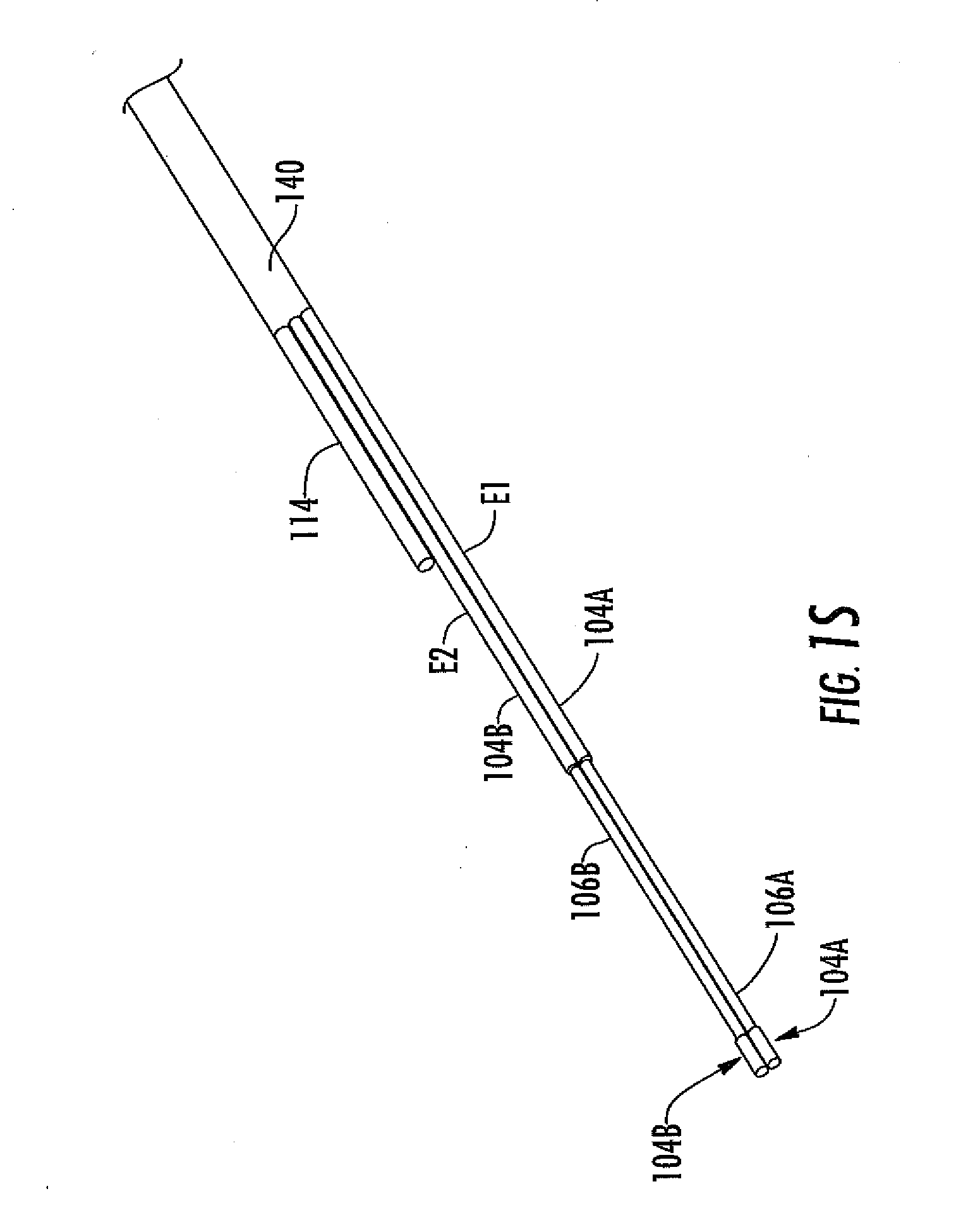
D00013
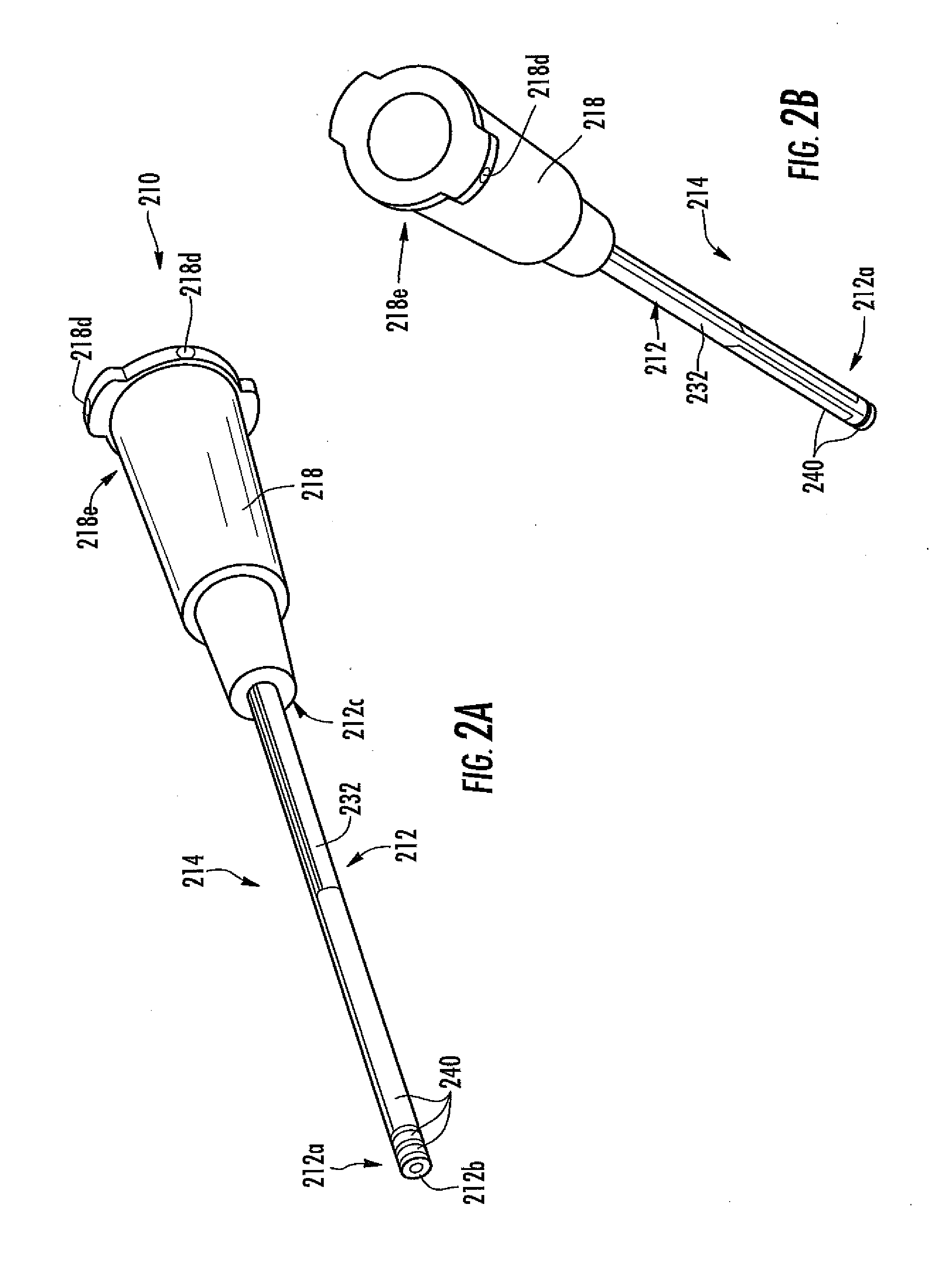
D00014

D00015
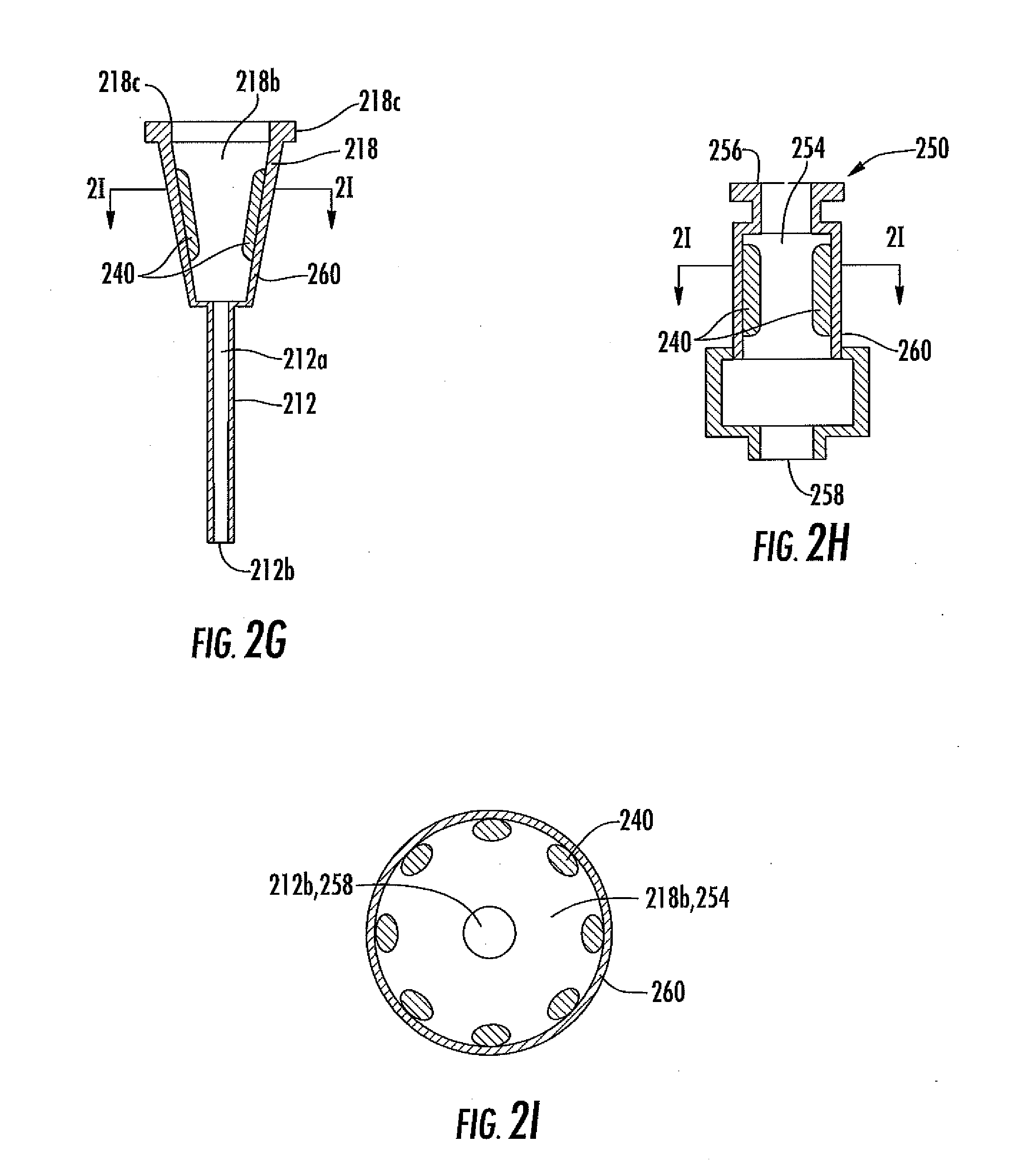
D00016
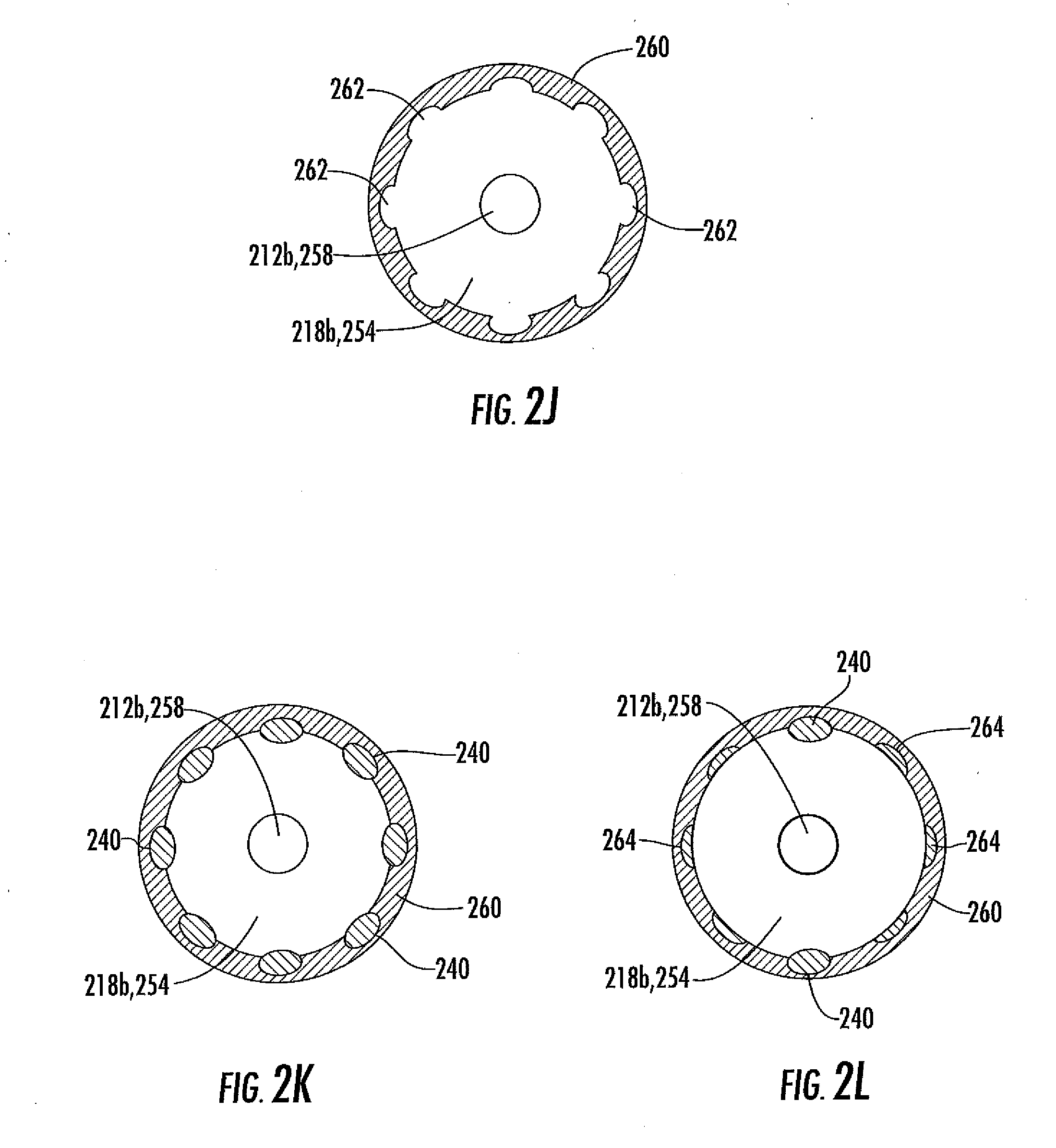
D00017
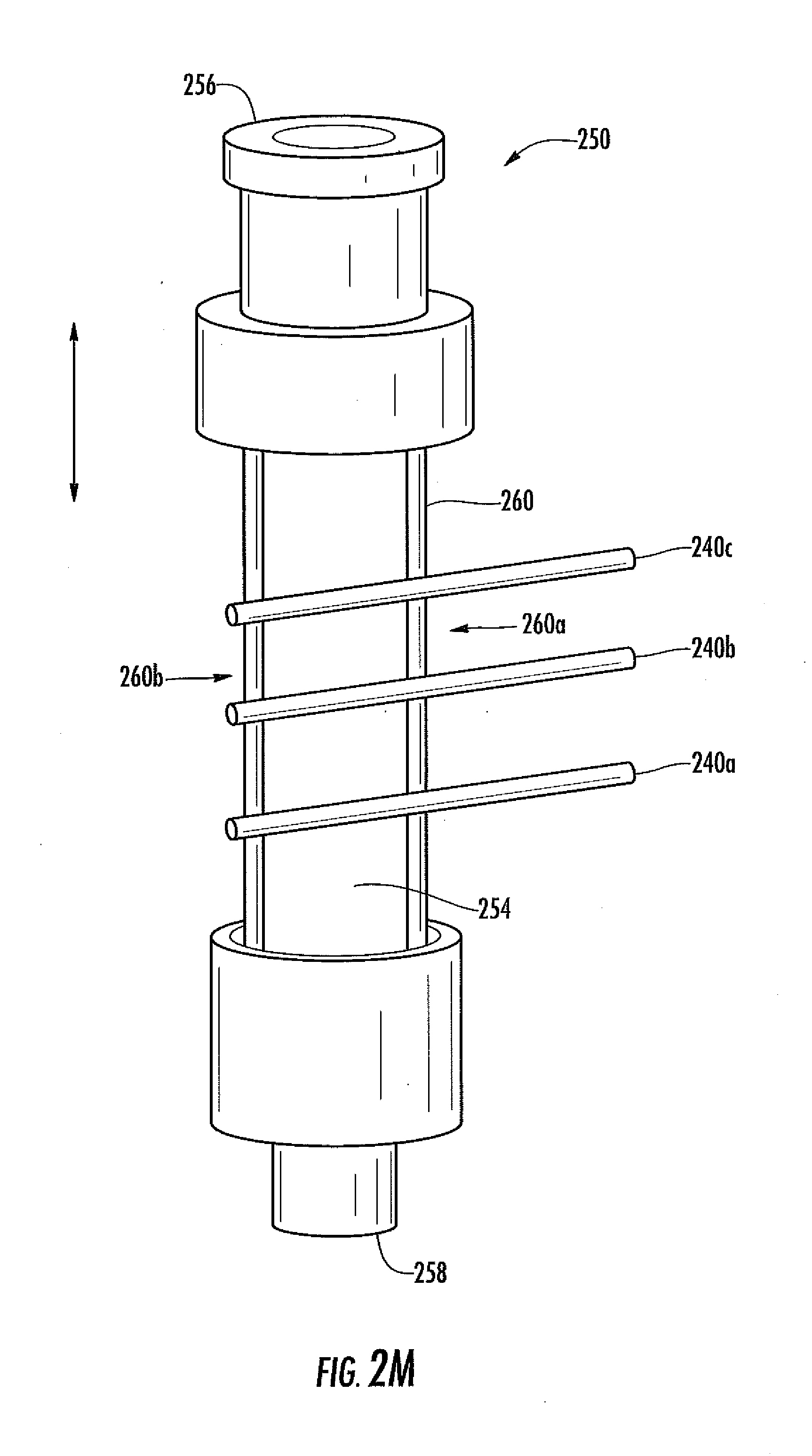
D00018
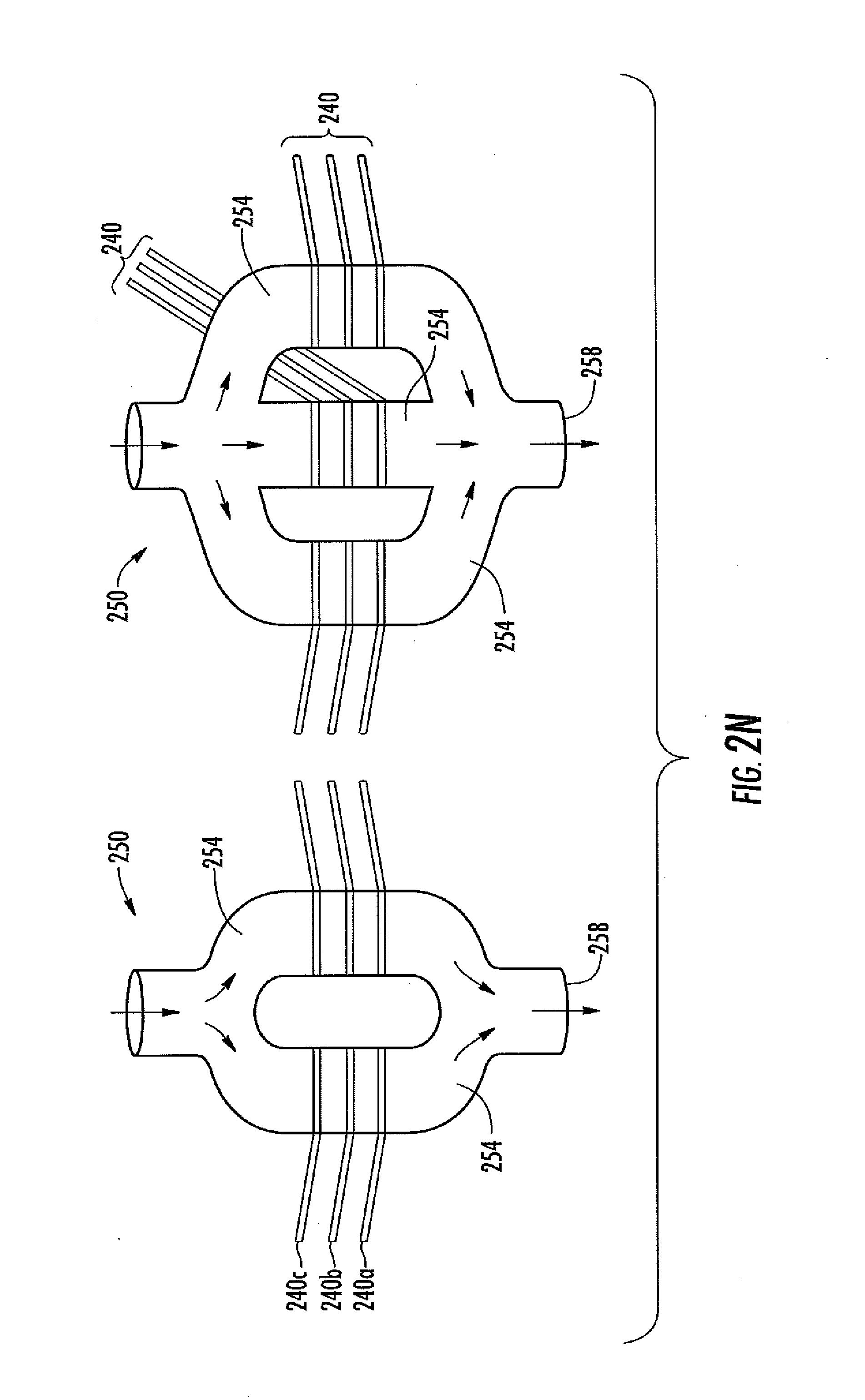
D00019
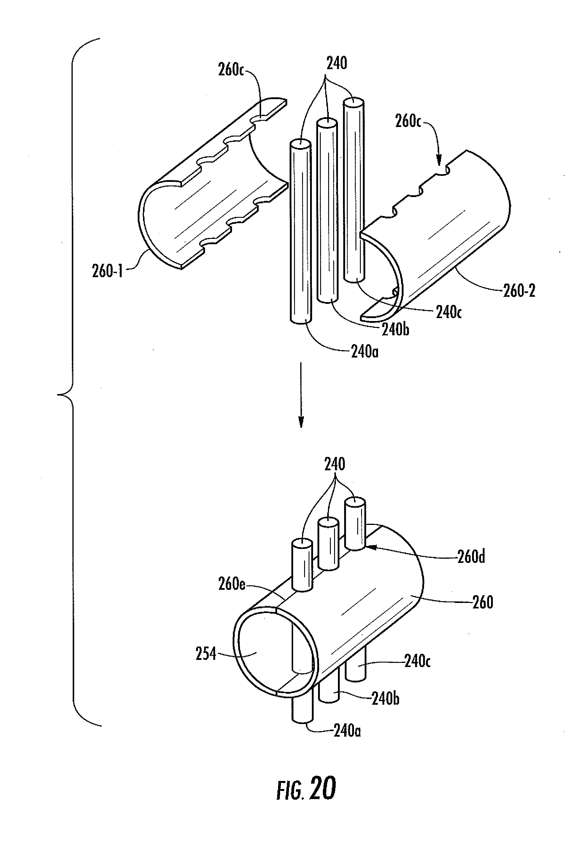
D00020
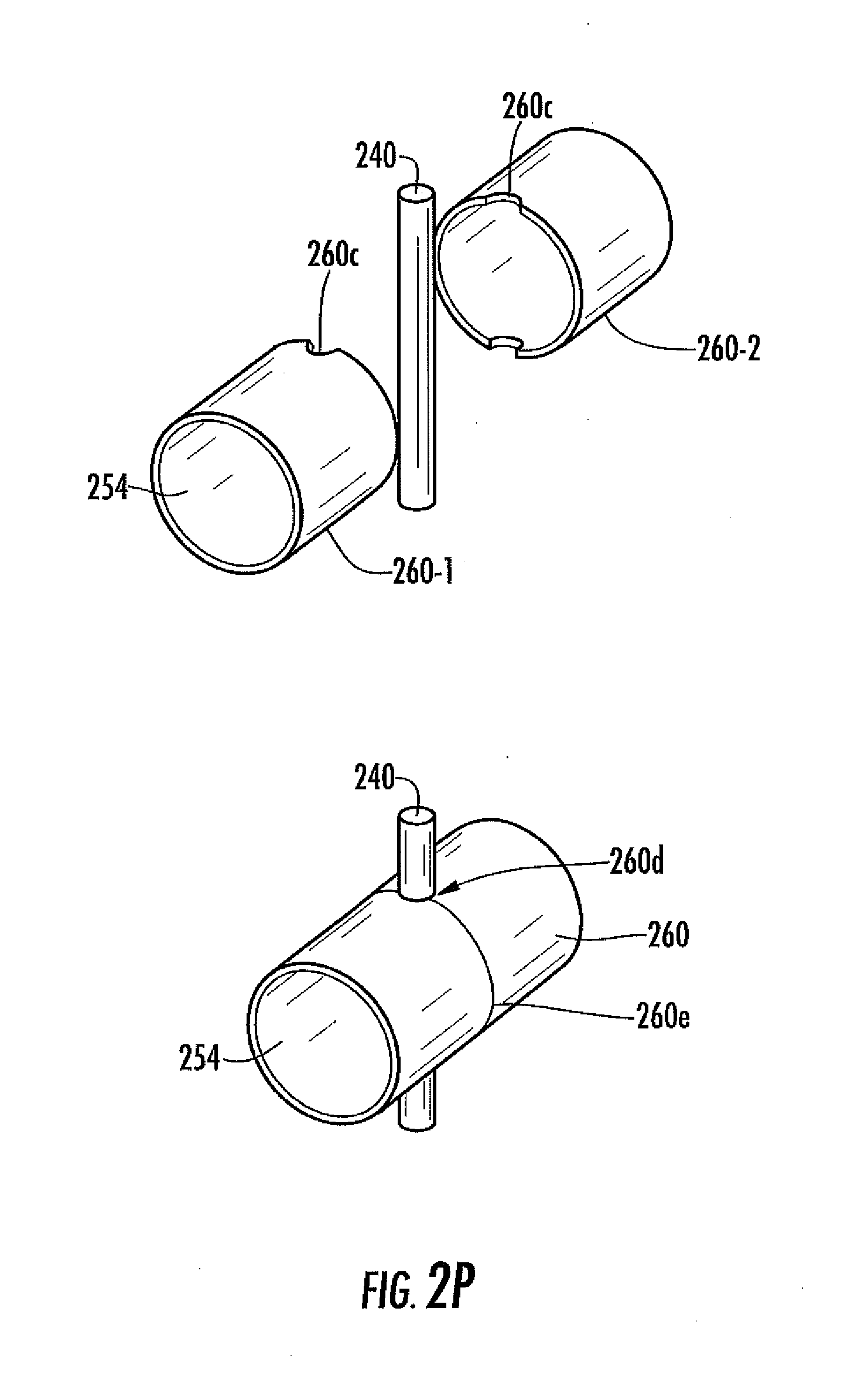
D00021

D00022
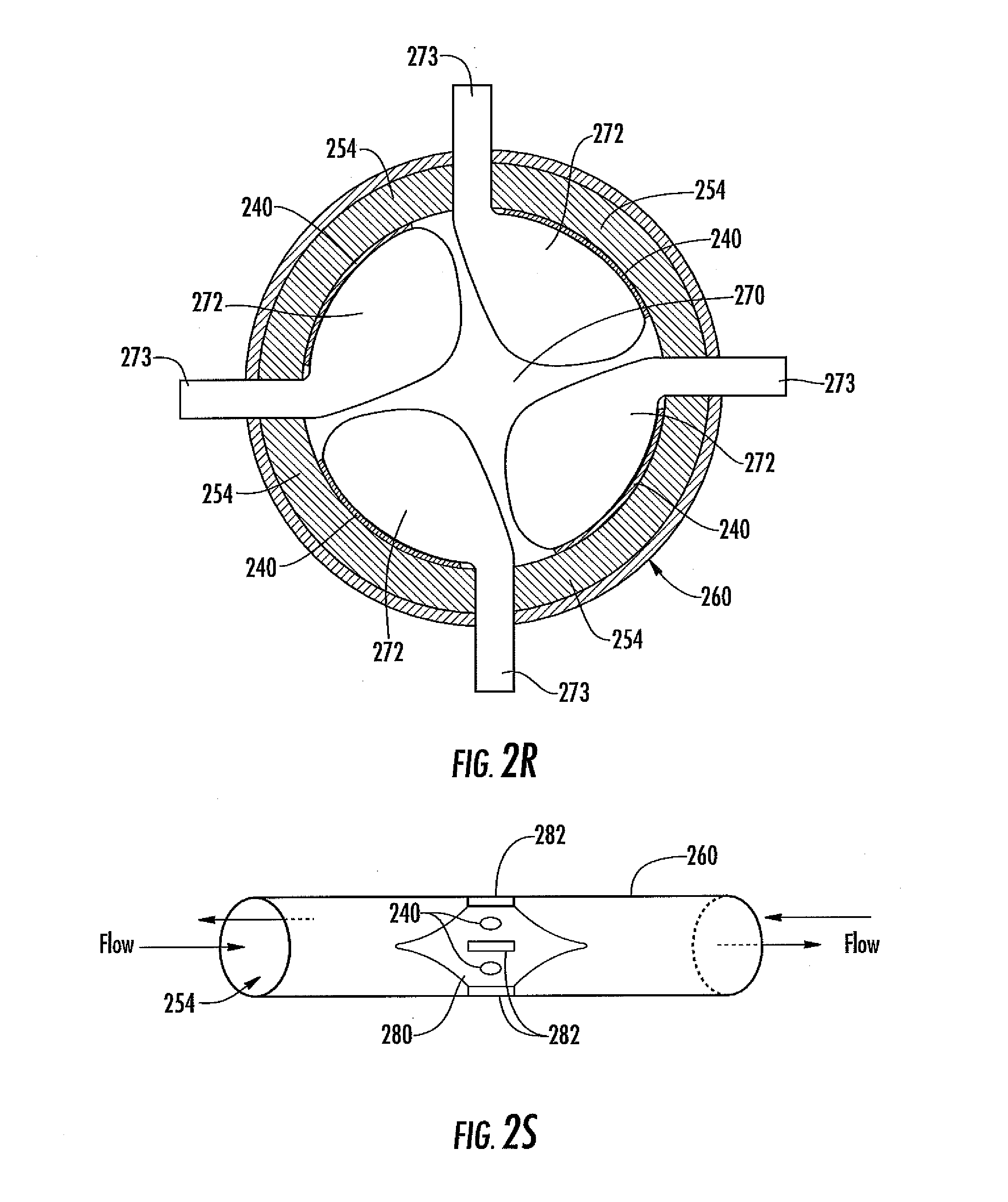
D00023
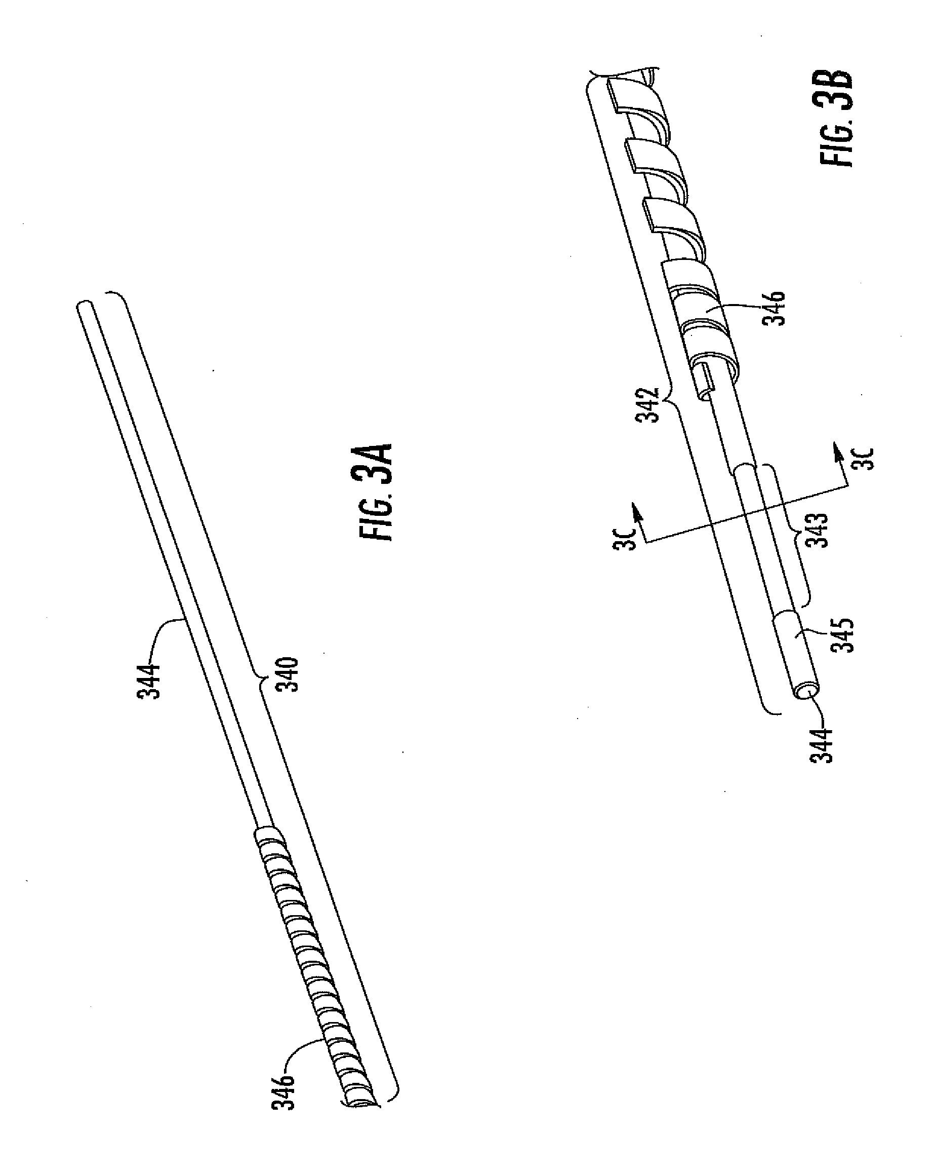
D00024
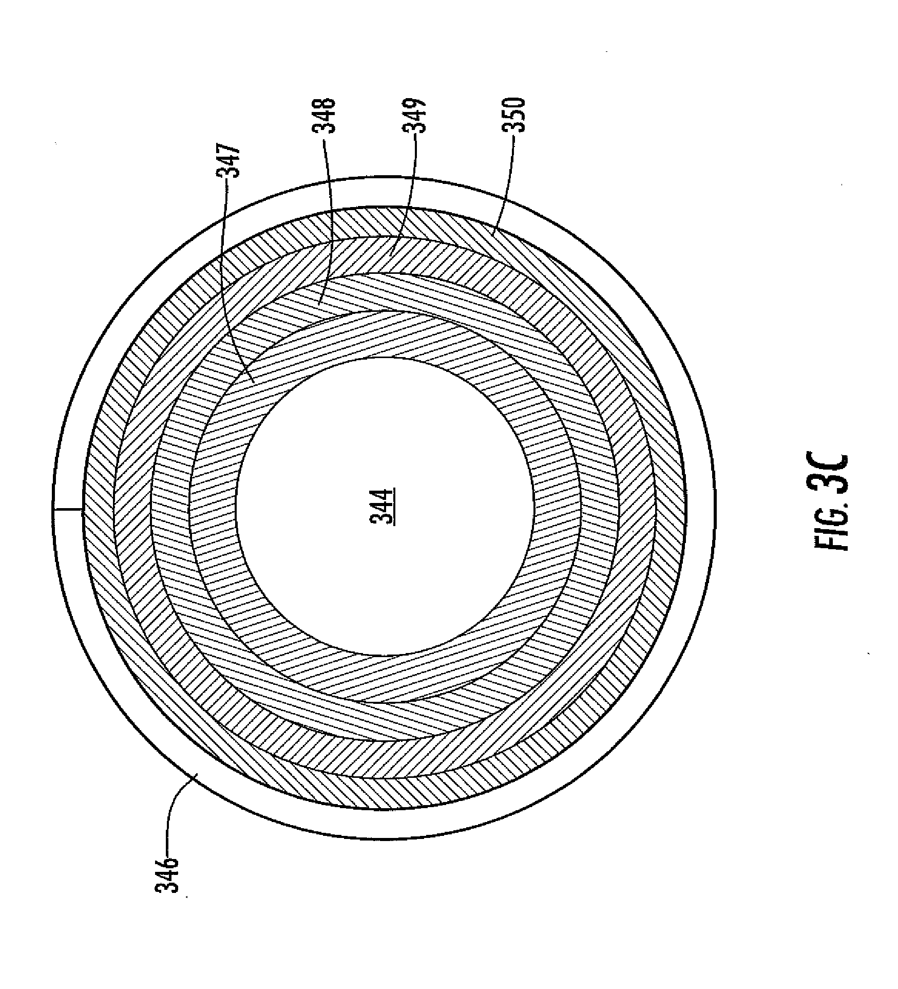
D00025

D00026
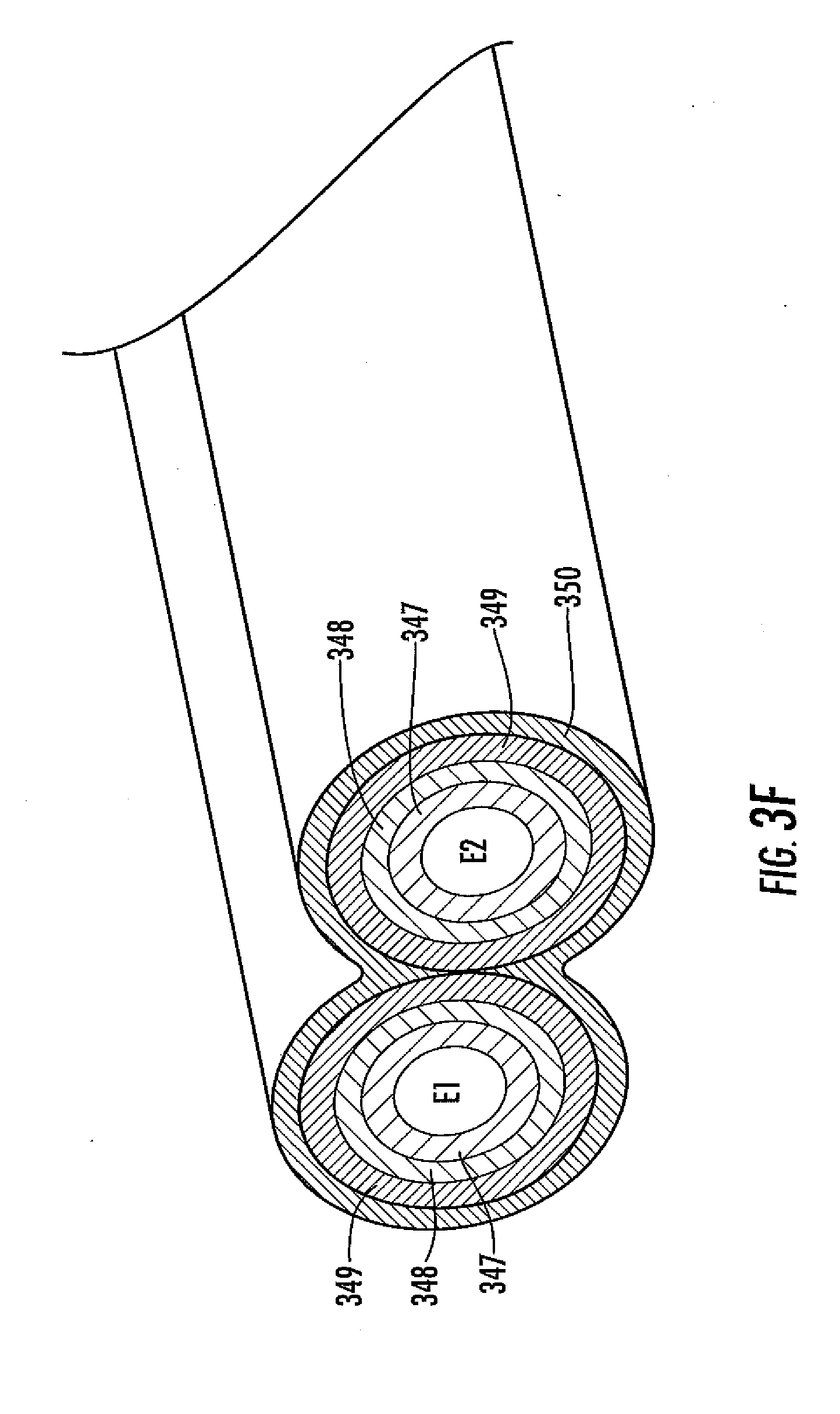
D00027
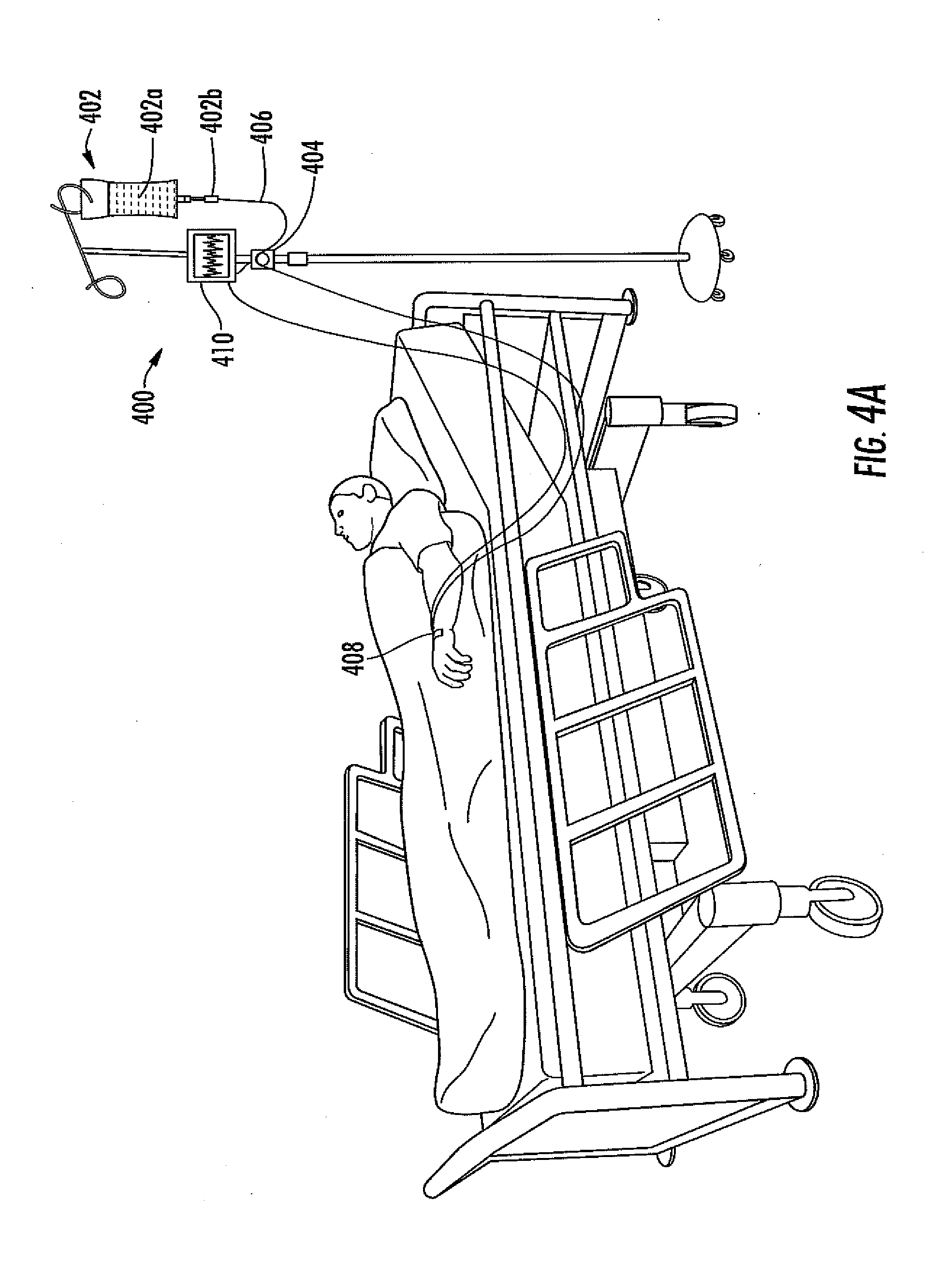
D00028
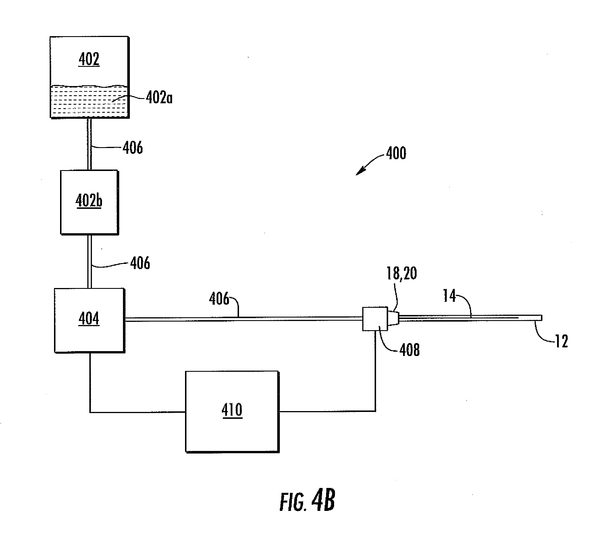
XML
uspto.report is an independent third-party trademark research tool that is not affiliated, endorsed, or sponsored by the United States Patent and Trademark Office (USPTO) or any other governmental organization. The information provided by uspto.report is based on publicly available data at the time of writing and is intended for informational purposes only.
While we strive to provide accurate and up-to-date information, we do not guarantee the accuracy, completeness, reliability, or suitability of the information displayed on this site. The use of this site is at your own risk. Any reliance you place on such information is therefore strictly at your own risk.
All official trademark data, including owner information, should be verified by visiting the official USPTO website at www.uspto.gov. This site is not intended to replace professional legal advice and should not be used as a substitute for consulting with a legal professional who is knowledgeable about trademark law.