Exercise Apparatus
Pedrera; Carlos A.
U.S. patent application number 12/827535 was filed with the patent office on 2010-12-30 for exercise apparatus. Invention is credited to Carlos A. Pedrera.
| Application Number | 20100331152 12/827535 |
| Document ID | / |
| Family ID | 43381379 |
| Filed Date | 2010-12-30 |


View All Diagrams
| United States Patent Application | 20100331152 |
| Kind Code | A1 |
| Pedrera; Carlos A. | December 30, 2010 |
EXERCISE APPARATUS
Abstract
One example embodiment includes an exercise apparatus. The exercise apparatus includes a band hook bar, where the band hook bar includes one or more hook loops configured to releasably attach to one or more exercise bands and a post, where the post is configured to support the band hook bar and allow the user to adjust the position of the band hook bar relative to the post. The exercise apparatus also includes a base, where the base is configured to support the exercise apparatus.
| Inventors: | Pedrera; Carlos A.; (Lincolnwood, IL) |
| Correspondence Address: |
    DLC PATENTS, PLLC
    13032 CRATER LAKE CIRCLE
    RIVERTON
    UT
    84065
    US
|
| Family ID: | 43381379 |
| Appl. No.: | 12/827535 |
| Filed: | June 30, 2010 |
Related U.S. Patent Documents
| Application Number | Filing Date | Patent Number | ||
|---|---|---|---|---|
| 61221613 | Jun 30, 2009 | |||
| Current U.S. Class: | 482/129 |
| Current CPC Class: | A63B 21/0552 20130101; A63B 23/03575 20130101; A63B 2225/093 20130101; A63B 2208/0204 20130101; A63B 21/16 20130101; A63B 23/0233 20130101; A63B 2208/0238 20130101; A63B 2209/10 20130101; A63B 21/0557 20130101; A63B 21/0442 20130101; A63B 23/0211 20130101; A63B 2071/0633 20130101; A63B 2210/50 20130101 |
| Class at Publication: | 482/129 |
| International Class: | A63B 21/04 20060101 A63B021/04 |
Claims
1. An exercise apparatus, the apparatus comprising: a band hook bar, wherein the band hook bar includes one or more hook loops configured to releasably attach to one or more exercise bands; a post, wherein the post is configured to: support the band hook bar; and allow the user to adjust the position of the band hook bar relative to the post; and a base, wherein the base is configured to support the exercise apparatus.
2. The apparatus of claim 1, further comprising: a locking mechanism, wherein the locking mechanism is configured to allow movement of the post relative to the base.
3. The apparatus of claim 2, wherein the locking mechanism further includes a locking plate; and a spring loaded pin.
4. The apparatus of claim 3, wherein: the spring loaded pin further includes a spring loaded pin handle; the locking plate further includes a notch, wherein the notch is configured to receive at least a portion of the spring loaded pin handle the spring loaded pin handle and the notch are configured to lock the spring loaded pin in position in the locking plate.
5. The apparatus of claim 1, further comprising: an exercise instruction board.
6. The apparatus of claim 5, wherein the exercise instruction board further includes: graphics for instructing a user in proper use of the exercise apparatus.
7. The apparatus of claim 1, wherein the band hook bar includes: five hook loops.
8. The apparatus of claim 1, wherein the band hook bar includes: a collar, wherein the collar is configured to connect the band hook bar to the post.
9. The apparatus of claim 1, wherein the post includes: one or more attachment points, wherein the one or more attachment points are configured to releasably attach the band hook bar.
10. The apparatus of claim 1, wherein the base is substantially U shaped.
11. An exercise system, the system comprising: a band hook bar, wherein the band hook bar includes one or more hook loops configured to releasably attach to one or more exercise bands; a post, wherein the post is configured to: support the band hook bar; and allow the user to adjust the position of the band hook bar relative to the post; a base, wherein the base is configured to support the exercise apparatus; and a locking mechanism, wherein the locking mechanism is configured to allow movement of the post relative to the base, and wherein the locking mechanism includes: a spring loaded pin, wherein the spring loaded pin includes a handle; and a locking plate, wherein the locking plate includes a notch, wherein the notch is configured to prevent movement of the handle.
12. The system of claim 0, wherein the locking mechanism further includes: a groove wherein the groove is configured to allow the spring loaded pin to move along the groove.
13. The system of claim 12, wherein the notch is at a first location along the groove and the locking mechanism includes a second notch at a second location along the groove.
14. The system of claim 0, wherein the band hook bar includes: a collar, wherein the collar is configured to connect the band hook bar to the post.
15. The system of claim 14, wherein the band hook bar includes: a locking pin, wherein the locking pin is configured to pass through a hole in the collar into one of one or more pinholes in the post, locking the position of the band hook bar relative to the post.
16. A method of manufacturing an exercise system, the method comprising: providing a band hook bar, wherein the band hook bar includes one or more hook loops configured to releasably attach to one or more exercise bands; providing a post, wherein the post is configured to: support the band hook bar; and allow the user to adjust the position of the band hook bar relative to the post; providing a base, wherein the base is configured to support the exercise apparatus; and providing a locking mechanism, wherein the locking mechanism is configured to allow movement of the post relative to the base, and wherein the locking mechanism includes: a spring loaded pin, wherein the spring loaded pin includes a handle; and a locking plate, wherein the locking plate includes a notch, wherein the notch is configured to prevent movement of the handle.
17. The method of claim 16 further comprising: providing an exercise instruction board, wherein the exercise instruction board includes graphics for instructing a user in proper use of the apparatus.
18. The method of claim 16 further comprising: providing an anchor clip, wherein the anchor clip is configured to releasably attach the one or more exercise bands to the band hook bar.
19. The method of claim 16 further comprising: providing a storage area, wherein the storage area includes: a hook, wherein the one or more exercise bands can be hung on the hook; and a hook and loop fastener, wherein the hook and loop fastener is configured to secure the one or more exercise bands to one another.
20. The method of claim 16 wherein the bank hook bar includes five hook loops.
Description
CROSS-REFERENCE TO RELATED APPLICATIONS
[0001] This application claims the benefit of and priority to U.S. Provisional Patent Application Ser. No. 61/221,613 filed on Jun. 30, 2009, which application is incorporated herein by reference in its entirety.
BACKGROUND OF THE INVENTION
[0002] The benefits of exercise are numerous and well documented. Exercise can reduce the instance and severity of many diseases. In addition, exercise can make a person feel better about themselves and provide the user with increased self-confidence and feelings of self-worth. However, many would be exercisers are intimidated about going to a gym and being surrounded by people that they perceive to be in better shape than they are.
[0003] Home exercise machines continue to gain in popularity as they become more light weight and increasingly versatile. Home exercise machines allow a user to workout at home rather than travel to a location with exercise equipment, such as a gym or recreational facility. Nevertheless, home exercise machines continue to suffer a number of drawbacks.
[0004] In particular, many home exercise machines target only a single region of the body. The machines are not adjustable or configurable for other regions of the user's body. Therefore, a user is forced to either purchase a large number of different machines or workout only specific regions of the body. This, in turn, limits the user's ability to get the maximum health benefits from their workout.
[0005] Additionally, many exercise machines continue to use weights to provide the necessary resistance for the workout. The weights can often weigh hundreds of pounds or more and are bulky to deal with. Additionally, the weights can pose an injury risk if they are inadequately secured or dropped. If the user struggles with the weight or suffers an injury while exercising, the weight can even prove fatal as it can restrict the user's ability to breathe or cause other injuries.
[0006] Further, many exercise machines take up a significant amount of space. In some cases, the user may have to dedicate an entire room to exercise equipment in order to provide the necessary space. Many exercise machines are complicated to set up or are difficult to take apart on a regular basis, forcing the user to dedicate the space full-time for the exercise machine.
[0007] In addition, many exercise machines do not provide any information on proper exercise technique or set-up or only provide the names of exercises that can be done. For a novice user, the information can be intimidating, discouraging the user from following through and continuing to exercise.
[0008] Accordingly, there is a need in the art for a single home exercise machine that can work out multiple regions of the body, providing a high amount of benefit for the cost and space used. In addition, there is a need in the art for an exercise machine that takes a minimum of space and is easily stored. Further, there is a need for an exercise machine that does not use weights to provide the necessary resistance. Finally, there is a need for an exercise machine that includes all of the information that the user will need to perform the desired exercises in an easy to understand manner.
BRIEF SUMMARY OF SOME EXAMPLE EMBODIMENTS
[0009] This Summary is provided to introduce a selection of concepts in a simplified form that are further described below in the Detailed Description. This Summary is not intended to identify key features or essential characteristics of the claimed subject matter, nor is it intended to be used as an aid in determining the scope of the claimed subject matter.
[0010] One example embodiment includes an exercise apparatus. The exercise apparatus includes a band hook bar, where the band hook bar includes one or more hook loops configured to releasably attach to one or more exercise bands and a post, where the post is configured to support the band hook bar and allow the user to adjust the position of the band hook bar relative to the post. The exercise apparatus also includes a base, where the base is configured to support the exercise apparatus.
[0011] Another example embodiment includes an exercise system. The exercise system includes a band hook bar, where the band hook bar includes one or more hook loops configured to releasably attach to one or more exercise bands and a post, where the post is configured to support the band hook bar and allow the user to adjust the position of the band hook bar relative to the post. The exercise system also includes a base, where the base is configured to support the exercise apparatus and a locking mechanism, where the locking mechanism is configured to allow movement of the post relative to the base. The locking mechanism includes a spring loaded pin, where the spring loaded pin includes a handle and a locking plate, where the locking plate includes a notch and where the notch is configured to prevent movement of the handle.
[0012] Another example embodiment includes a method of manufacturing an exercise system. The method includes providing a band hook bar, where the band hook bar includes one or more hook loops configured to releasably attach to one or more exercise bands and providing a post, where the post is configured to support the band hook bar and allow the user to adjust the position of the band hook bar relative to the post. The method also includes providing a base, where the base is configured to support the exercise apparatus, and providing a locking mechanism, where the locking mechanism is configured to allow movement of the post relative to the base. The locking mechanism includes a spring loaded pin, where the spring loaded pin includes a handle, and a locking plate, where the locking plate includes a notch, and where the notch is configured to prevent movement of the handle.
[0013] These and other objects and features of the present invention will become more fully apparent from the following description and appended claims, or may be learned by the practice of the invention as set forth hereinafter.
BRIEF DESCRIPTION OF THE DRAWINGS
[0014] To further clarify various aspects of some example embodiments of the present invention, a more particular description of the invention will be rendered by reference to specific embodiments thereof which are illustrated in the appended drawings. It is appreciated that these drawings depict only illustrated embodiments of the invention and are therefore not to be considered limiting of its scope. The invention will be described and explained with additional specificity and detail through the use of the accompanying drawings in which:
[0015] FIG. 1A illustrates a front perspective view of the exercise apparatus;
[0016] FIG. 1B illustrates a side view of the exercise apparatus;
[0017] FIG. 1C illustrates a top view of the exercise apparatus;
[0018] FIG. 2 illustrates a cross-sectional top view of the exercise apparatus;
[0019] FIG. 3 illustrates an alternative cross-sectional top view of the exercise apparatus;
[0020] FIG. 4 illustrates an alternative cross-sectional top view of the exercise apparatus;
[0021] FIG. 5A illustrates a perspective view of the post in the first position;
[0022] FIG. 5B illustrates a cross-sectional view of the post in the first position;
[0023] FIG. 6A illustrates a perspective view of the spring loaded pin handle of FIG. 5A removed from the notch;
[0024] FIG. 6B illustrates a cross-sectional view of the spring loaded pin handle of FIG. 5B removed from the notch;
[0025] FIG. 7 illustrates an example of a locking pin used to hold the band hook bar in position relative to the post;
[0026] FIG. 8 illustrates an example of a storage area;
[0027] FIG. 9 illustrates an example of an exercise instruction board;
[0028] FIG. 10 illustrates an example of the exercise apparatus in storage position;
[0029] FIG. 11 illustrates an example of the operation of the exercise apparatus;
[0030] FIG. 12 illustrates an example of an anchor clip; and
[0031] FIG. 13 is a flow-chart illustrating an example of a method for producing an exercise apparatus.
DETAILED DESCRIPTION OF SOME EXAMPLE EMBODIMENTS
[0032] Reference will now be made to the figures wherein like structures will be provided with like reference designations. It is understood that the figures are diagrammatic and schematic representations of some embodiments of the invention, and are not limiting of the present invention, nor are they necessarily drawn to scale.
[0033] FIGS. 1A, 1B and 1C illustrate an example of an exercise apparatus 5. FIG. 1A illustrates a front perspective view of the exercise apparatus 5; FIG. 1B illustrates a side view of the exercise apparatus 5; and FIG. 1C illustrates a top view of the exercise apparatus 5. In at least one implementation, the exercise apparatus 5 can allow a user to perform a number of different types of exercise. In particular, the exercise apparatus 5 can allow a user to change the set-up of the exercise apparatus to perform different exercises. For example, the exercise apparatus can be configured to allow the user to perform a variety of shoulder exercises including forward shoulder press, shoulder pull and rotator cuff rotation, chest and upper back exercises including chest pull, chest fly and back rows, arm exercises including standing bicep curls, triceps kickback and overhead triceps extension, abdominal and lower back exercises including resisted abdominal crunch, standing abdominal twist and resisted side bends, and leg exercises including hip extensions, laying leg curls and front leg kicks.
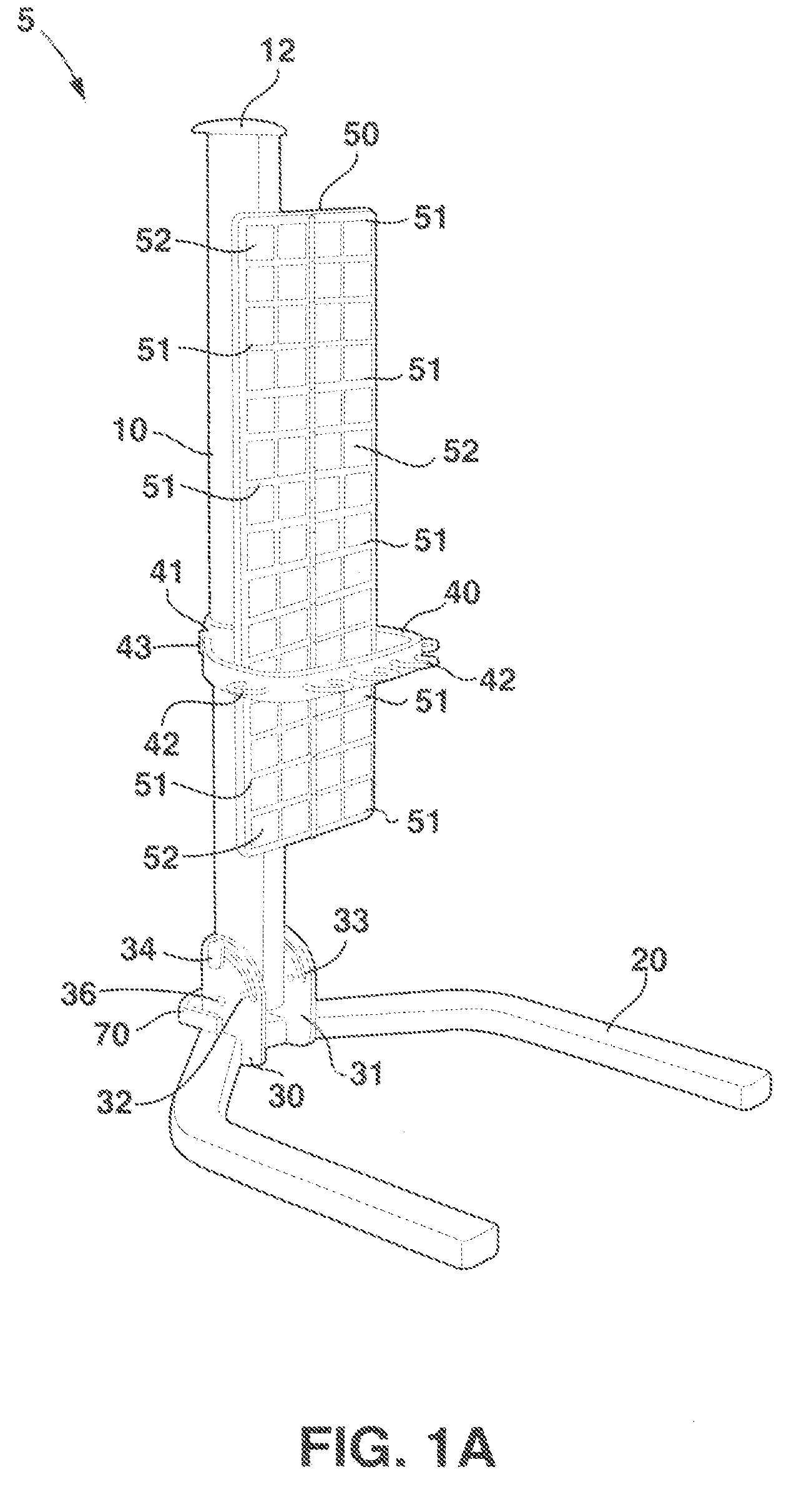
[0034] FIGS. 1A, 1B and 1C show that the exercise apparatus 5 can include a post 10. In at least one implementation, the post 10 can be configured to support the other elements of the exercise apparatus 5. In particular, the post 10 can include a hollow shaft and can be aligned in a vertical direction while the exercise apparatus 5 is configured for use by a user. The post 10 can be of sufficient height to allow different users to perform a variety of exercises. For example, the post 10 can be six feet tall and have a diameter of four to five inches.
[0035] In at least one implementation, the post 10 can be made of steel. Additionally or alternatively, the post 10 can be made of any material that is strong enough to support the other elements of the exercise apparatus 5. In particular, the exercise apparatus can be made of aluminum, iron, titanium, wood or any other material of sufficient strength to support the other elements of the exercise apparatus 5.
[0036] FIGS. 1A, 1B and 1C also show that the exercise apparatus 5 can include a cap 12. In at least one implementation, the cap 12 can be used to ensure that the top of the post is covered and decrease the chance of injury if a user contacts the post 10. Additionally or alternatively, the cap 12 can serve as an ornamental feature of exercise apparatus 5. In particular, cap 12 can be inserted into the hollowed out opening located at the top of the post 10, therefore, the cap 12 will have a diameter slightly smaller than the inside diameter of the post 10. Additionally or alternatively, cap 12 can be placed over the outside of post 10, with the cap 12 having a diameter slightly larger than the outside diameter of the post 10. The cap 12 can made out of plastic or any other material that allows the cap to perform its desired function.
[0037] FIGS. 1A, 1B and 1C further show that the exercise apparatus 5 can include a base 20. In at least one implementation, the base 20 can add mass to the entire exercise apparatus 5. In particular, the base 20 can be constructed out of steel or other metals. The additional mass imparted by the base 20 can stabilize the exercise apparatus 5 while the exercise apparatus 5 is being used by a user. Additionally or alternatively, the extra mass imparted by base 20 can allow the exercise apparatus 5 to provide the necessary resistance for the user to perform a proper exercise routine, as discussed below.
[0038] In at least one implementation, the base 20 can be shaped in such a way as to allow the user an unobstructed exercise space in front of the exercise apparatus 5. In addition, the base 20 can be shaped to allow the exercise apparatus to be placed in a storage position, as described below. In particular, the base 20 can be substantially U shaped. As used in the specification and in the claims the term substantially U shaped shall mean that the base includes a first portion with two arms extending from the first portion and substantially perpendicular to the first portion. For example, the base 20 can have an inside width of about 32 inches, outside width of about 40 inches and a depth (end of post to end of arms) of about 42 inches. Additionally or alternatively, the base 20 can be other shapes that allow the base 20 to perform its intended functions.
[0039] FIGS. 1A, 1B and 1C also show that the exercise apparatus 5 can include a locking mechanism 30. In at least one implementation, the locking mechanism 30 can allow the post 10 to more relative to the base 20. In particular, the locking mechanism 30 can allow the post to move between one or more exercise positions and a storage position. For example, the post 10 can be oriented perpendicular to the plane of the base 20, which can allow a user to exercise. Additionally or alternatively, the post 10 can be oriented parallel to the plane of the base 20, which can allow the exercise apparatus 5 to be stored when not in use, as described below.
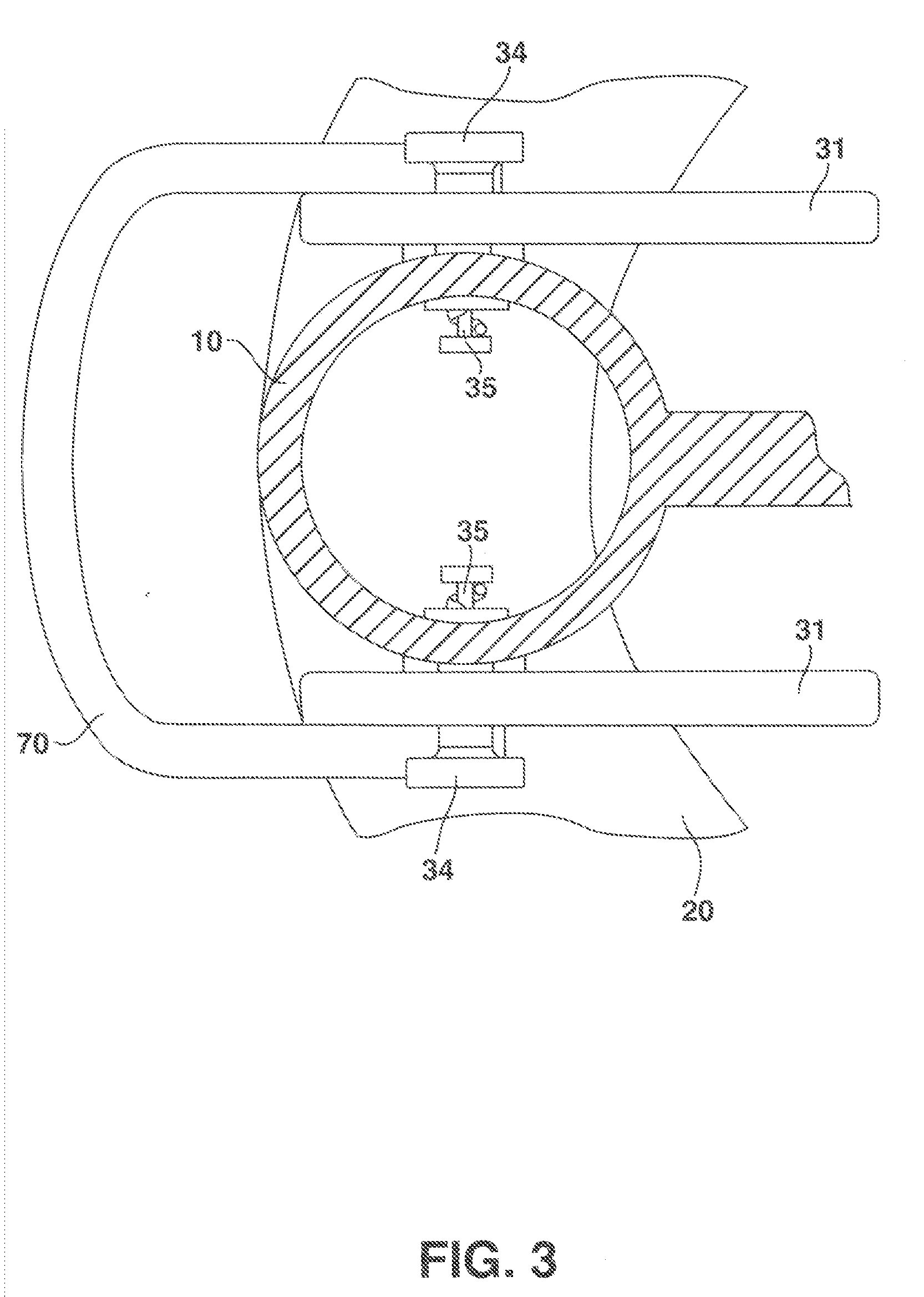
[0040] FIGS. 1A, 1B and 1C further show that the locking mechanism 30 can include a locking plate 31. In at least one implementation, the locking plate 31 can be used to ensure that the other elements of the locking mechanism 30 work with one another, as described below. The locking plates 31 can be made of steel, aluminum, iron, titanium or any other material of sufficient strength to support the other elements of the exercise apparatus 5. The locking plates 30 can be ten inches tall and seven inches wide.
[0041] FIGS. 1A, 1B and 1C also show that the locking mechanism 30 can include notches 32. In at least one implementation, the notches 32 can allow the post 10 to lock in position relative to the base 20. In particular, the notches 32 can be used to ensure that the post 10 does not move relative to the base, as described below. For example, the notches 32 can lock the post 10 in one or more exercise positions or in a storage position, as described below.
[0042] FIGS. 1A, 1B and 1C further show that the locking mechanism 30 can include a locking plate groove 33. In at least one implementation, the groove 33 can provide a predetermined path to move the post 10 from the one or more workout positions to other positions, such as the storage position or other workout positions, and vice versa. In at least one implementation, the locking plate groves 33 are machined out of the locking plates 31. Additionally or alternatively, the locking plates 31 can be created with grooves 33 already present.
[0043] FIGS. 1A, 1B and 1C also show that the locking mechanism 30 can include spring loaded pin handles 34. In at least one implementation, the spring loaded pin handles 34 can allow the user to manually activate and use the locking mechanism 30. In particular, the spring loaded pin handles 34 can provide a means whereby a user is able to move the exercise apparatus 5 between various positions as described below.
[0044] In at least one implementation, the spring loaded pin handles 34 are configured to securely lock into the upper and lower locking plate notches 32. In particular, the spring loaded pin handles can be configured such that when they are engaged into the upper locking plate notches the exercise apparatus 5 will not move positions when the user is exercising. Additionally or alternatively, when the spring loaded pin handles 34 are engaged into the lower locking plate notches the exercise apparatus 5 will not move when being stored away.
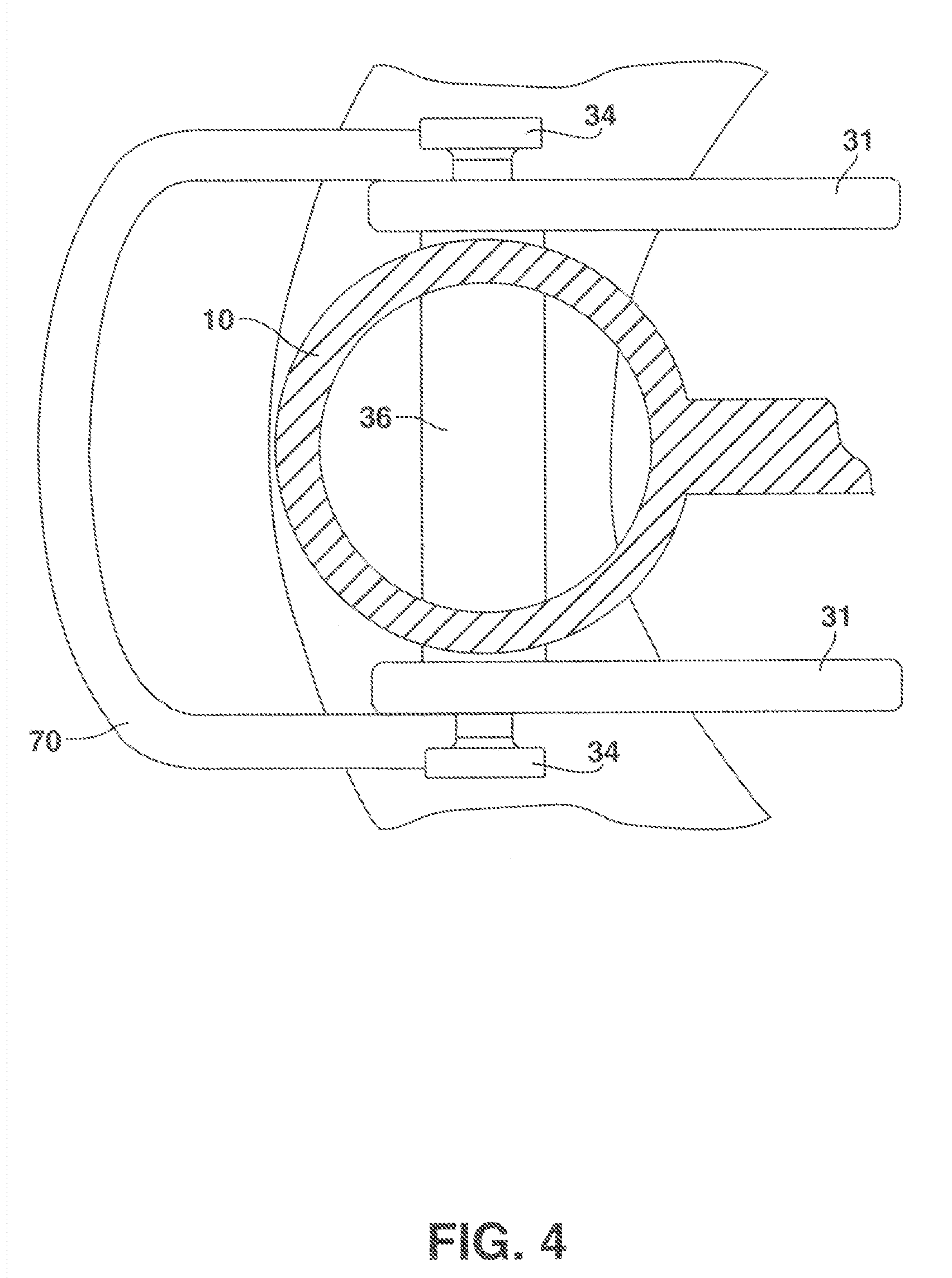
[0045] FIGS. 1A, 1B and 1C further show that the exercise apparatus 5 can include a central pivot bar 36 that passes through the post 10 and is connected to the locking plates 31. In at least one implementation, the central pivot bar 36 can act as a pivot point between the post 10 and the base 20. In particular, the central pivot bar 36 can allow a smooth transition of the post 10 from the one or more workout positions to the storage position and vice versa. For example, the central pivot bar 36 can be circular in shape allowing the post 10 to easily roll along the path of the locking plate groves 33, as discussed below. In at least one implementation, the central pivot bar 36 can be made of steel, aluminum, iron, titanium or any other material of sufficient strength to support the other elements of the exercise apparatus 5.
[0046] FIGS. 1A, 1B and 1C also show that the exercise apparatus 5 can include a band hook bar 40. In at least one implementation, the band hook bar 40 can move relative to the post 10 to allow the user to perform a variety of exercises, as described below. In particular, moving the band hook bar 40 can allow the exercise apparatus 5 to be placed in different configurations, allowing a user to target different muscle groups using different exercises. The band hook bar 40 can be 2.5 inches high.
[0047] In at least one implementation, the band hook bar 40 will resist the movements of the user, allowing the muscles of the user to be exercised. Accordingly, the band hook bar 40 should be able to resist potentially large forces. In particular, the band hook bar 40 can be made out of steel. Additionally or alternatively, the band hook bar 40 can be made of aluminum, iron, titanium or any other material of sufficient strength.
[0048] FIGS. 1A, 1B and 1C further show that the band hook bar 40 can include a collar 41. In at least one implementation, the collar 41 allows the band hook bar 40 to move easily relative to the post 20. In particular, the collar 41 can have a diameter slightly larger than the diameter of the post 20 to allow the collar to move relative to the post 20 while maintaining support between the collar 41 and the post 20. The band hook bar 40 can be approximately thirteen inches deep. Additionally or alternatively, the collar 41 can be five inches high to allow the post 10 to exert sufficient lateral force on the collar 41 to prevent movement of the collar 41.
[0049] FIGS. 1A, 1B and 1C show that the band hook bar 40 can include one or more hook loops 42. In at least one implementation, the one or more hook loops 42 can allow the user to releasably attach exercise bands 61 to the band hook bar 40 via the anchor clip, as discussed below. In particular, the hook loops 42 protrude from the band hook bar 40 to provide attachment points for the exercise bands 61, as described below. In at least one implementation, the band hook bar 40 can include five hook loops 42. The hook loops 42 can be approximately 2.5 inches in diameter.
[0050] FIGS. 1A, 1B and 1C also show that the exercise apparatus 5 can include a locking pin 43. In at least one implementation, the locking pin can securely connect the band hook bar 40 to the post 10. In particular, the locking pin 43 has an outer handle that allows the user to easily grip the locking pin 43. In addition, the pin portion of the locking pin 43 can be configured to pass through a hole in the collar 41 into the post 10, such that movement of the collar 41 relative to the post 20 is arrested. For example, the locking pin 43 can be three inches long with a two inch diameter.
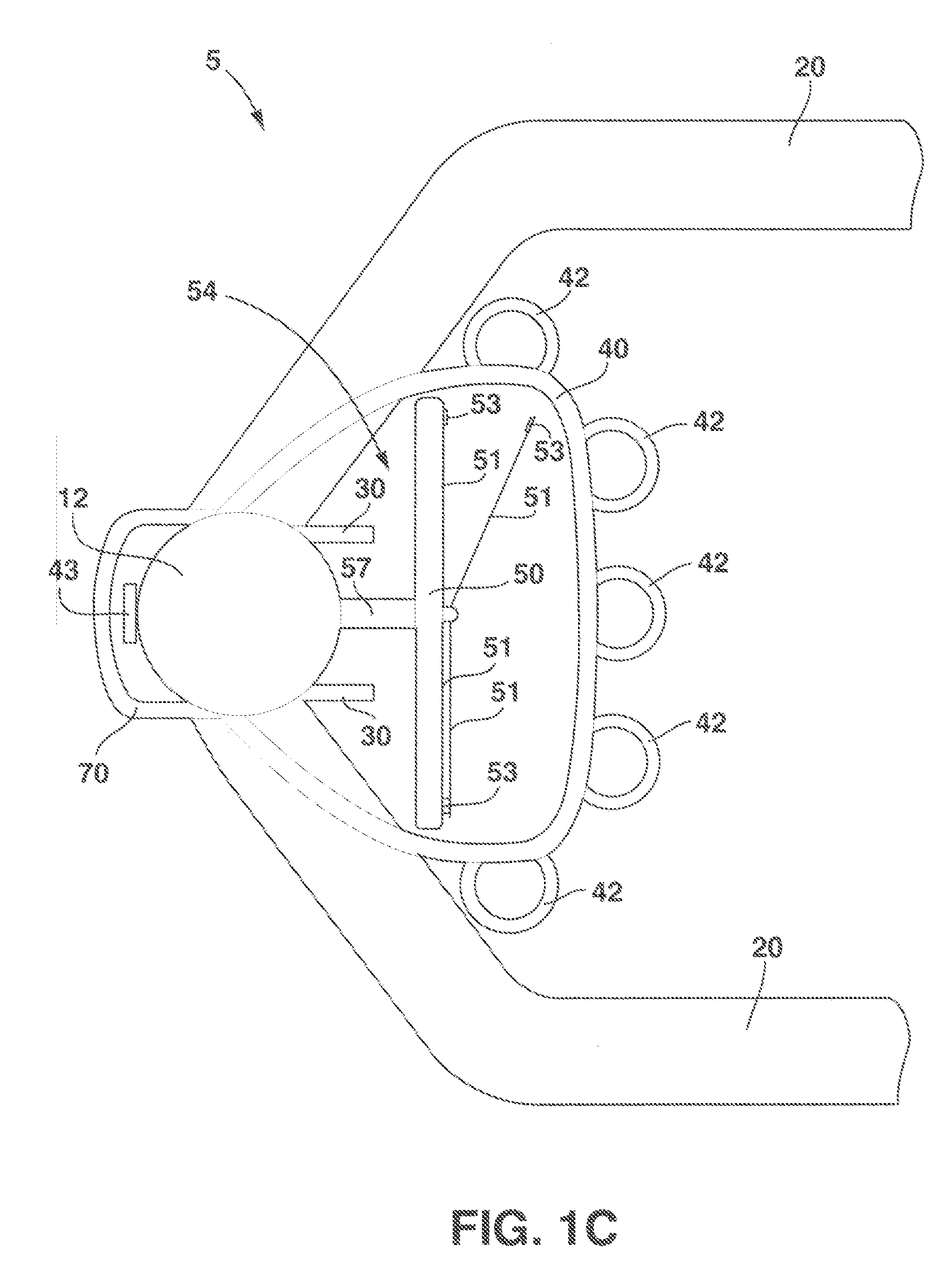
[0051] FIGS. 1A, 1B and 1C further show that the exercise apparatus 5 can include an exercise instruction board 50. In at least one implementation, the exercise instruction board 50 can display all the various exercises possible using the exercise apparatus 5. In particular, the exercise instruction board 50 can include exercise cards that are in front of the user while exercising, allowing them to understand the exercises and maintain proper form while exercising, as discussed below. The exercise instruction board 50 can be approximately sixteen inches wide and 50.5 inches tall. Additionally or alternatively, the bottom of the exercise instruction board 50 can be twenty inches from the bottom of the base 20.
[0052] FIGS. 1A, 1B and 1C also show that the exercise instruction board 50 can include one or more flipbook pages 51. In at least one implementation, the flipbook pages 51 can hold one or more exercise cards. In particular, the user can move the flipbook pages 51 from right to left and left to right displaying more exercise cards as needed. The flipbook pages 51 can be approximately seven inches wide and 9.5 inches tall.
[0053] FIGS. 1A, 1B and 1C further show that the one or more flipbook pages 51 can include one or more exercise card pockets 52. For example, each flipbook page 51 can include six exercise card pockets 52. In at least one implementation, the one or more exercise card pockets 52 provide a pocket into which an exercise card can be slid. In particular, the one or more exercise card pockets 52 can include an opening wherein the user can insert and remove exercise cards as needed. For example the exercise card pockets 52 can be approximately three inches wide and three inches tall.
[0054] In at least one implementation, the flipbook pages 51 are made out of a hard transparent plastic. One of skill in the art will appreciate that where the flipbook page 51 has been pressed to form exercise card pockets 52 the plastic may no longer be transparent. In particular, the hard transparent plastic can allow the user to view exercise cards through the exercise card pockets 52, as discussed below. Additionally or alternatively, a flipbook page 51 of hard transparent plastic can allow the user to view the exercise cards while simultaneously protecting the exercise cards from excessive wear.
[0055] In at least one implementation, the exercise instruction board 50 can be broken down into five zones, where each zone corresponds to a major muscle group and each zone includes four flipbook pages 51. In particular, the exercise instruction board 50 can include five flipbooks that correspond to the shoulders zone, the chest and upper back zone, the arms zone, the abs and lower back zone, and the legs zone with multiple flipbook pages 51 in each zone. For example, the exercise instruction board 50 can include five zones with four flip book pages 51 in each zone and six exercise card pockets 52 in each flip book page 51 for a total of 120 exercises that can be displayed on the exercise instruction board 50.
[0056] FIGS. 1A, 1B and 1C also show that the flipbook pages 51 can include magnetic page locks 53. In at least one implementation, the magnetic page locks 53 can secure the flipbook pages 51 to each other and to the exercise instruction board 50, thereby keeping the proper exercise cards in front of the user while exercising. In particular, the magnetic page locks 53 can be connected to the upper corner of each of the flipbook pages 51. For example, if the exercise instruction board 50 has five zones with four flipbook pages 51 in each zone, then the exercise instruction board 50 can include a total of twenty magnetic page locks 53.
[0057] FIGS. 1A, 1B and 1C further show that the exercise apparatus 5 can include a storage area 54 for storing exercise bands 61. In at least one implementation, the storage area 54 can be located in the posterior section of the exercise instruction board 50. In particular, the storage area 54 can include a portion of the exercise instruction board 50 and can be made out of the same material as the exercise instruction board 50.
[0058] FIGS. 1A, 1B and 1C also show that the exercise storage area 54 can include an upper hook 55. In at least one implementation, the upper hook 55 can provide a hook that is wide enough to hold at least a portion of the exercise bands 61 in place. In particular, the user can place the middle portion of the exercise bands 61 over the upper hook 55. In at least one implementation, the upper hook 55 is located in the upper quartile of the storage area 54.
[0059] FIGS. 1A, 1B and 1C further show that the exercise storage area 54 can include a hook and loop fastener 56. In at least one implementation, the hook and loop fastener 56 can wrap around the lower portion of the exercise bands 61 and temporarily secure them into place. In particular, the hook and loop fastener 56 can be configured to secure the exercise bands 61 to one another and keep the exercise bands 61 in the center of the exercise instruction board 50 when the exercise apparatus 5 is placed in a storage position. In at least one implementation, the hook and loop fastener 56 can be located in the lower quartile of the storage area 54.
[0060] FIGS. 1A, 1B and 1C also show that the exercise apparatus 5 can include brackets 57. In at least one implementation, the brackets 57 can connect the post 10 to the exercise instruction board 50. In particular, the brackets 57 can support the exercise instruction board 50 and can leave a space between the instruction board 50 and the post 10 to create a storage area 54. For example, the brackets 57 can be in the top 1/8th of the storage area 54 and the bottom 1/8th of the storage area 54. The brackets 57 can be 1.5 inches wide, 1/4 inch thick and four inches long.
[0061] FIGS. 1A, 1B and 1C further show that the exercise apparatus 5 can include exercise bands 61. In at least one implementation, the exercise bands 61 can allow a method of weighted resistance for the user while exercising. In particular, the exercise bands 61 can include rubber or other elastic materials. As the user attempts to stretch the exercise bands 61 the exercise bands 61 resist stretching, providing a known resistance for the user.
[0062] FIGS. 1A, 1B and 1C also show that the exercise apparatus 5 can include a handle 70. In at least one implementation, the handle can provide a means for the user to move the entire exercise apparatus 5 from one location to another as described below. In particular, the handle 70 can be connected to the locking mechanism 30 and the base 20. The handle 70 can be 73/4 inches wide, 1.5 inches tall and four inches deep.
[0063] FIG. 2 illustrates a cross-sectional top view of the exercise apparatus 5. FIG. 2 shows that the post 10 can include one or more pinholes 11. In at least one implementation, the pinholes 11 can be used to connect the post 10 to other elements of the exercise apparatus 5. In particular, a locking pin 43 can be inserted through the collar 41 of the band hook bar 40 into one of the one or more pinholes 11. The one or more pinholes 11 can be equidistantly spaced along the post 10. For example, the pinholes 11 can be spaced 1.5 inches apart, for a total of 43 pinholes 11 in the post 10. Additionally or alternatively, the one or more pinholes 11 can be placed along non-equidistant intervals.
[0064] FIG. 2 also shows that the locking pin 43 can extend through the collar 41 into one of the one or more pinholes 11. In at least one implementation, this can allow the band hook bar 40 to be secured in position relative to the post 10. In particular, the locking pin 43 can prevent movement of the band hook bar 40 while a user is exercising or while the exercise apparatus is being stored.
[0065] FIG. 3 illustrates an alternative cross-sectional top view of the exercise apparatus 5. FIG. 3, shows that the locking mechanism 30 can include a spring loaded pin 35. In at least one implementation, the spring loaded pin 35 can pass through the locking plate 31 into the post 10. In particular, the spring loaded pin 35 is spring loaded to pull the pin further into the post. The spring can prevent the spring loaded pin 35 from being completely disengaged and can allow the post 10 to be secured relative to the base 20, as discussed below.
[0066] FIG. 4 illustrates an alternative cross-sectional top view of the exercise apparatus 5. FIG. 4 shows that the central pivot bar 36 can pass through the post 10 and connect to the locking plates 31. In at least one implementation, the central pivot bar 36 can act as a pivot point between the post 10 and the base 20. In particular, the central pivot bar 36 can allow a smooth transition of the post 10 from the one or more workout positions to the storage position and vice versa. For example, the central pivot bar 36 can be circular in shape allowing the post 10 to easily roll along the path of the locking plate groves 33, as discussed below. In at least one implementation, the central pivot bar 36 can be made of steel, aluminum, iron, titanium or any other material of sufficient strength to support the other elements of the exercise apparatus 5.
[0067] FIGS. 5A and 5B illustrate the post 10 locked in a first position relative to the locking mechanism 30. FIG. 5A illustrates a perspective view of the post 10 locked in the first position; and FIG. 5B illustrates a cross-sectional view of the post 10 locked in the first position. FIGS. 5A and 5B show that the spring loaded pin 35 passes through the groove 33 into the post 10. In the first position, at least a portion of the spring loaded pin handle 34 resides in notch 32. In at least one implementation, the portion of the handle 34 that resides in the notch 32 is configured to prevent movement of the post 10 relative to the locking mechanism 30 and, therefore, the base 20.
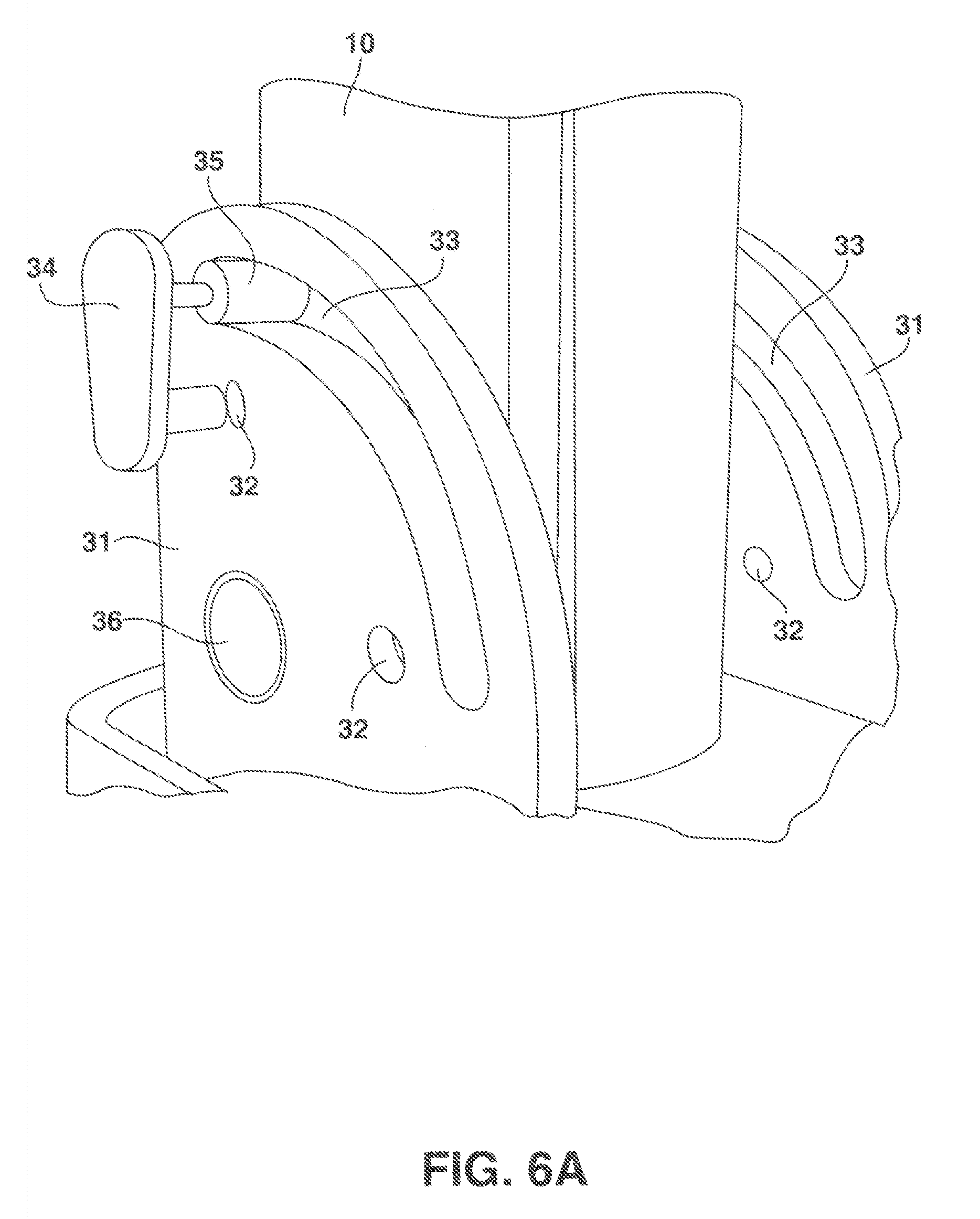
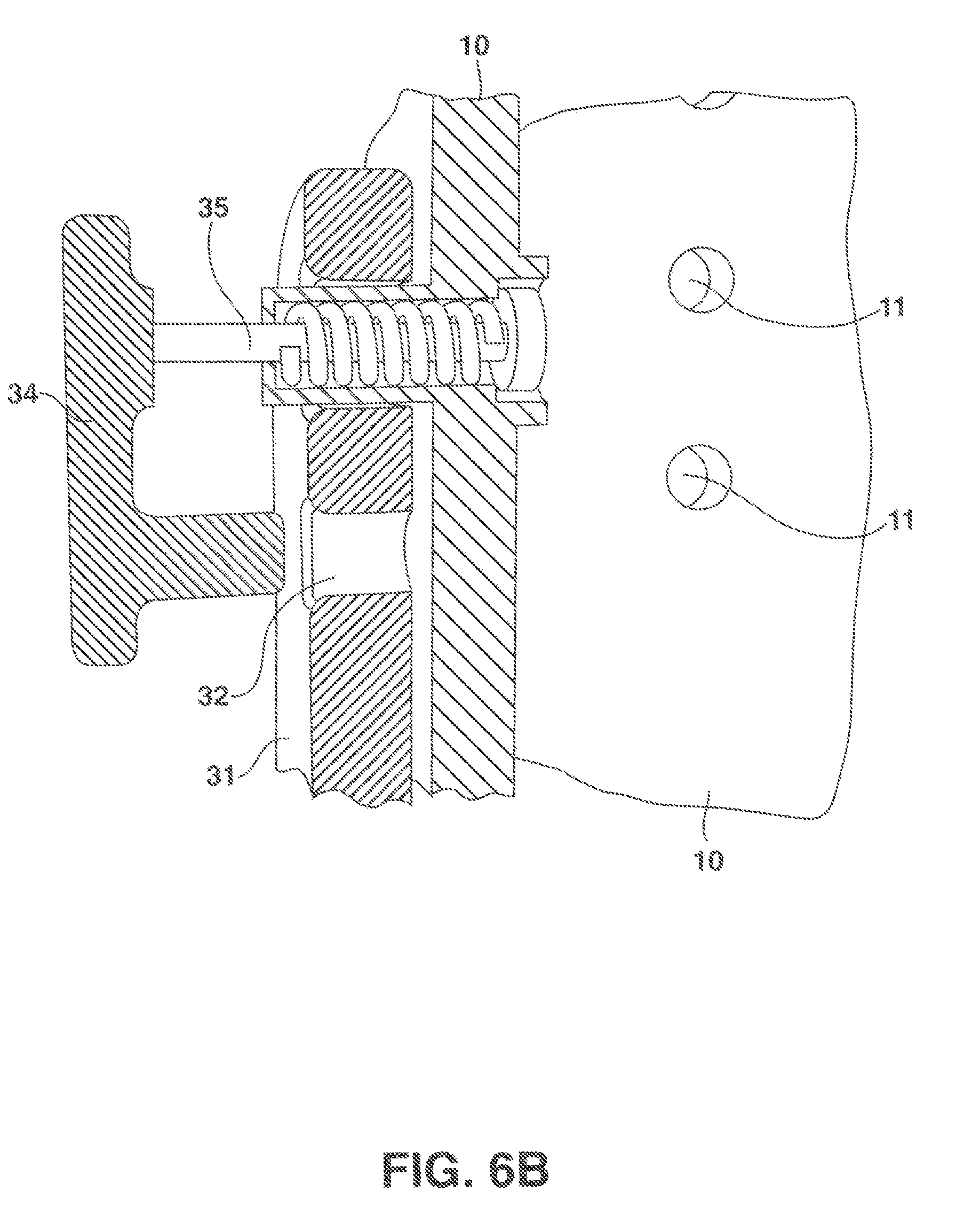
[0068] FIGS. 6A and 6B illustrate the spring loaded pin handle 34 of FIGS. 5A and 5B, respectively, removed from the notch 32. FIG. 6A illustrates a perspective view of the spring loaded pin handle 34 of FIG. 5A removed from the notch 32; and FIG. 6B illustrates a cross-sectional view of the spring loaded pin handle 34 of FIG. 5B removed from the notch 32. In at least one implementation, when the handle 34 is removed from the notch 32, the spring loaded pin 35 can move freely through groove 33.
[0069] FIG. 7 illustrates an example of the locking pin 43 used to hold the band hook bar 40 in position relative to the post 10. In at least one implementation, The locking pin 43 passes through the collar 41 into one or more pinholes 11 in the post 10. In particular, the locking pin 43 can include a durable material, such as steel, that is capable of supporting the weight of the band hook bar 40, even when the band hook bar 40 is subjected to stress due to a user's exercise.
[0070] In at least one implementation, the locking pin 43 can include a straight pin that can be removed to adjust the position of the band hook bar 40 relative to the post 10. Additionally or alternatively, the locking pin 43 can include a spring loaded pin that cannot be entirely removed by the user.
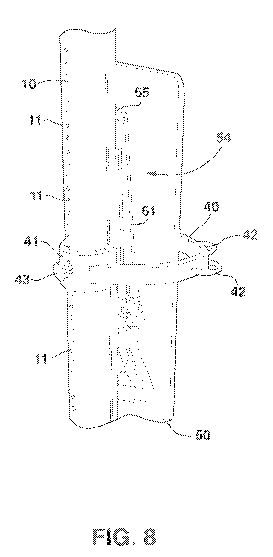
[0071] FIG. 8 illustrates an example of the storage area 54. In at least one implementation, the storage area 54 can be located in the posterior section of the exercise instruction board 50. In particular, the storage area 54 can include a portion of the exercise instruction board 50 and can be made out of the same material as the exercise instruction board 50.
[0072] FIG. 8 shows that the exercise storage area 54 can include an upper hook 55. In at least one implementation, the upper hook 55 can provide a hook that is wide enough to hold at least a portion of the exercise bands 61 in place. In particular, the user can place the middle portion of the exercise bands 61 over the upper hook 55. In at least one implementation, the upper hook 55 is located in the upper quartile of the storage area 54.
[0073] FIG. 8 shows also that the exercise storage area 54 can include a hook and loop fastener 56. In at least one implementation, the hook and loop fastener 56 can wrap around the lower portion of the exercise bands 61 and temporarily secure them into place. In particular, the hook and loop fastener 56 can be configured to secure the exercise bands 61 to one another and keep the exercise bands 61 in the center of the exercise instruction board 50 when the exercise apparatus 5 is placed in a storage position. In at least one implementation, the hook and loop fastener 56 can be located in the lower quartile of the storage area 54.
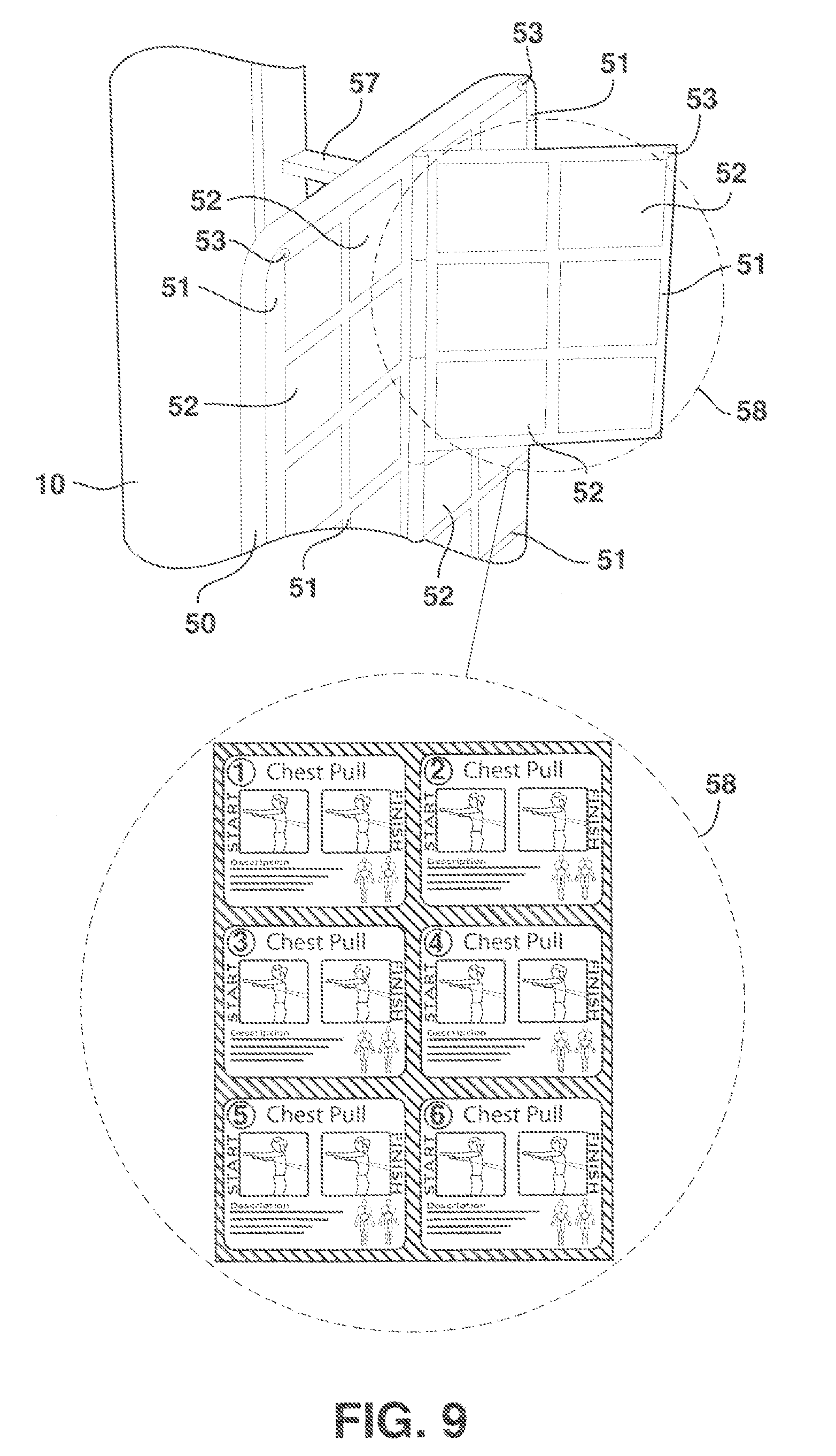
[0074] FIG. 9 illustrates an example of an exercise instruction board 50. In at least one implementation, an exercise instruction board 50 can allow a user to view possible exercises while performing the exercise or just prior to beginning the exercise. In at least one implementation, the exercise instruction board 50 can display all the various exercises possible. In particular, the exercise instruction board 50 can include exercise cards 58 in front of the user allowing them to understand the exercises and maintain proper form while exercising. For example, each exercise card pocket 52 can include a single exercise card 58 that is approximately three inches wide and three inches tall.
[0075] FIG. 9 shows that the exercise instruction board 50 can include one or more flipbook pages 51. In at least one implementation, the flipbook pages 51 can hold one or more exercise cards 58. In particular, flipbook pages 51 can include exercises that target different areas of the body. For example, the exercise instruction board 50 can include a first flipbook page 51 for shoulder exercises, a second flipbook page 51 for chest and upper back exercises, a third flipbook page 51 for arm exercises, a fourth flipbook page 51 for abdominal and lower back exercises and a fifth flipbook page 51 for leg exercises. The one or more flipbook pages 51 can be positioned vertically with respect to one another. Additionally or alternatively, the one or more flipbook pages 51 can be positioned sequentially to one another.
[0076] FIG. 9 shows that the one or more flipbook pages 51 can include one or more exercise card pockets 52. In at least one implementation, the one or more exercise card pockets 52 provide a pocket into which an exercise card 58 can be slid. In particular, the one or more exercise card pockets 52 can include an opening wherein the user can insert and remove exercise cards 58 as needed. For example, the one or more exercise pockets 52 can include an opening along the top of the pocket 52 which allows an exercise card 58 to be inserted into or removed from the exercise card pocket 52. Additionally or alternatively, the one or more exercise card pockets 52 can include an opening along one of the sides which allows an exercise card 58 to be inserted or removed.
[0077] In at least one implementation, the flipbook pages 51 are made out of a hard transparent plastic. In particular, the hard transparent plastic can allow the user to view exercise cards 58 through the flipbook pages 51. Additionally or alternatively, a hard transparent plastic can allow the user to view the exercise cards 58 while simultaneously protecting the exercise cards 58 from excessive wear. The hard transparent plastic can be used to form exercise card pockets 52 for inserting exercise cards 58. One of skill in the art will appreciate that where the flipbook page 51 has been pressed to form exercise card pockets 52 the plastic may no longer be transparent. Additionally or alternatively, hard transparent plastic can be used to laminate the exercise cards 58.
[0078] FIG. 9 shows that the flipbook pages 51 can include magnetic page locks 53. In at least one implementation, the magnetic page locks 53 can secure the flipbook pages 51 to each other and to the exercise instruction board 50, thereby keeping the proper exercise cards 58 in front of the user while exercising. In particular, the magnetic page locks 53 can be connected to the upper corner of the flipbook pages 51. Additionally or alternatively, the exercise instruction board 50 can be tilted slightly such that the flipbook pages 51 stay in place under the force of gravity or the flipbook pages 51 can include other fastener types for retaining the flipbook pages 51 in the proper position.
[0079] FIG. 9 shows that the flipbook pages 51 can include exercise cards 58. In at least one implementation, the exercise cards 58 can illustrate the exercise being performed along with descriptive text describing how to perform the exercises. In particular, the exercise cards 58 can include graphics for instructing a user in proper use of the exercise apparatus 5. In at least one implementation, the exercise cards 58 can include cardboard, photography paper or any other material capable of producing the required graphics and text.
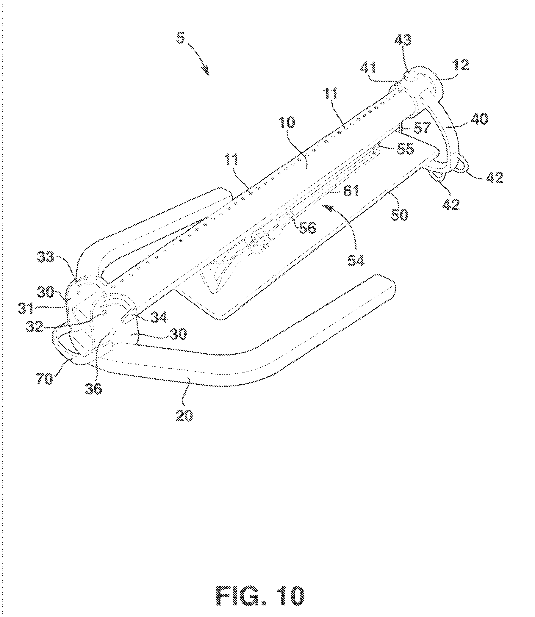
[0080] FIG. 10 illustrates an example of the exercise apparatus 5 in a storage position. In at least one implementation, the storage position allows the user to place the exercise apparatus 5 in a more compact configuration that allows the user to store the exercise apparatus 5. In particular, the storage position can allow the user to fold the exercise apparatus 5 flat, or nearly flat along the floor, allowing the user to store the exercise apparatus 5 under other furniture, such as a bed.
[0081] In at least one implementation, to move the post 10 from the workout position to the storage position the user first gets behind the exercise apparatus 5. The user then bends down and grabs both of the spring-loaded pin handles 34 and pulls both of the spring-loaded pin handles 34 outward. This action simultaneously increases the tension of the springs located inside the spring-loaded pins 35 and disengages the lower part of the spring-loaded pin handles 34 from the upper locking plate notches 32. The user now moves both spring-loaded pin handles 34 in a downward motion along the locking plate groves 33 until the post 10 is in the storage position. The user now releases each of the spring-loaded pin handles 34. This action simultaneously decreases some of the tension of the springs of the spring-loaded pins 35 and engages the lower part of the spring-loaded pin handles 34 into the lower locking plate notches 32; thereby, locking the post 10 into position. Assisting in the facilitation of the movement of the post 10 from the workout position to the storage position is the central pivot bar 36. The central pivot bar 36 helps rotate the post 10 along the path of the locking plate groves 33. In at least one implementation, the distance between the bottom of the base 20 and the top of the locking mechanism 30 can be eleven inches, making eleven inches the maximum height of the exercise apparatus 5 when in the storage position.
[0082] In at least one implementation, when the exercise apparatus 5 is in the storage position, the machine can be moved with the help of the handle 70. In particular, the handle 70 can be welded onto the base 20 and locking plates 31 so that when the user lifts on the handle 70, the user can lift the exercise apparatus 5. The user will grab the handle 70 with one or two hands and slide the exercise machine to their location of choice. In at least one implementation, rollers or other devices can be attached to the base 20 to facilitate movement of the exercise apparatus 5 while in the storage position.
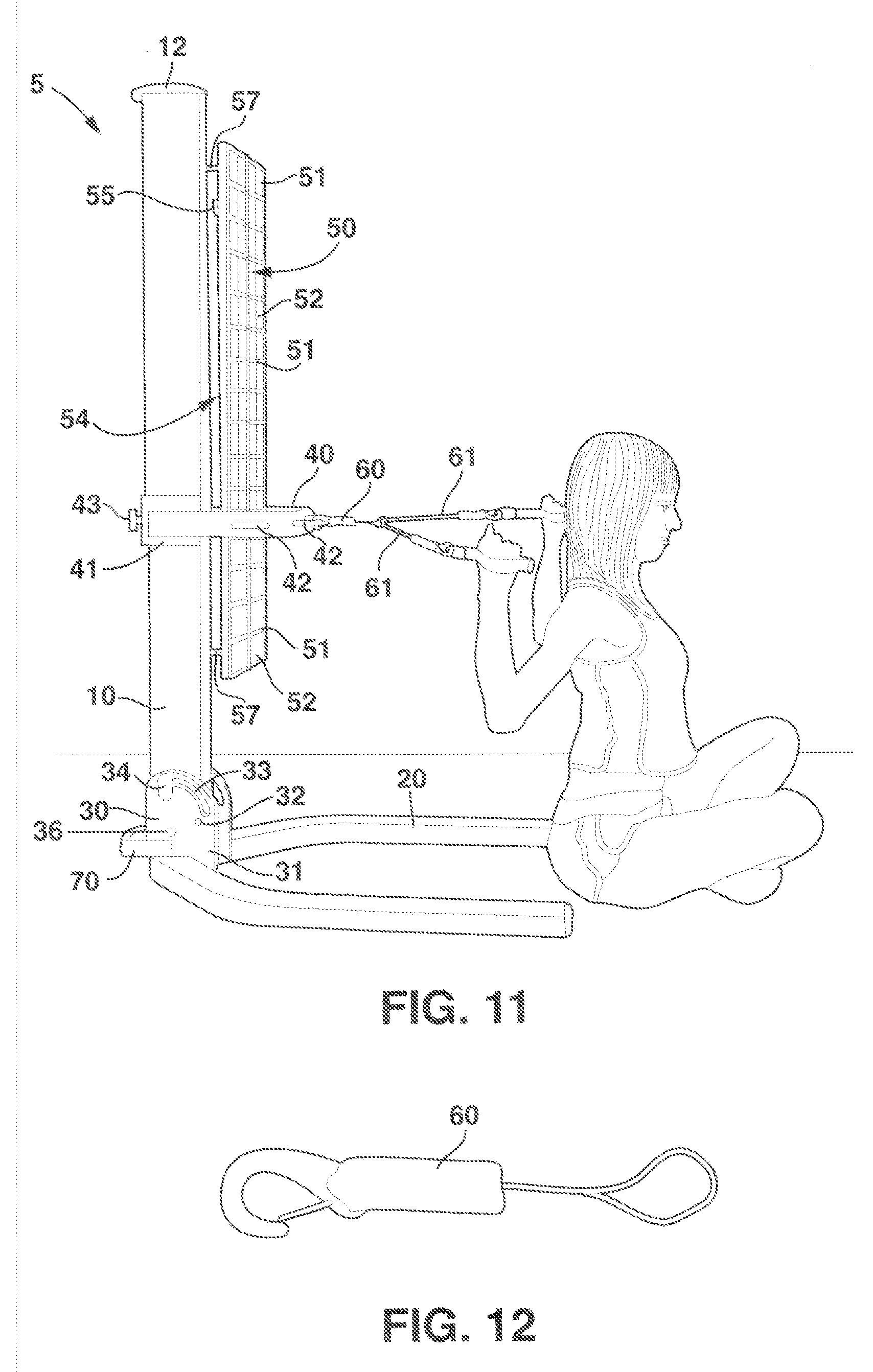
[0083] FIG. 11 illustrates an example of the operation of the exercise apparatus 5. In at least one implementation, the operation of the exercise apparatus can allow the user to exercise one or more muscles with the use of exercise bands 61. In particular, the user can select the muscles or muscle groups to exercise and the desired resistance and configure the exercise apparatus 5 as needed.
[0084] In at least one implementation, the user mentally chooses which body zone to exercise. An example would be the "legs zone." The user flips through the flipbook pages 51 of the exercise instruction board 50 looking for a specific exercise to perform. The flipbook pages 51 contain exercise cards 58 which are located in transparent exercise card pockets 52. The exercise cards 58 contain all the different exercises that are possible using the exercise apparatus 5. There are magnetic page locks 53 located on the corner of each flipbook page 51. The magnetic page locks 53 hold the flipbook pages 51 in place so the chosen exercise cards 58 are always facing the user while they exercise. Each exercise designates a specific height that the band hook bar 40 needs to be at to perform a specific exercise. The user decides which exercise they want to perform. An example would be "leg extensions" from the "legs zone." The user grabs and pulls out the locking pin 43 with one hand and with the other hand grabs the band hook bar 40. So the user now has completely pulled out the locking pin 43 with one hand and is holding the band hook bar 40 with the other hand. Based upon the exercise they are going to perform they are either going to move the band hook bar 40 up or down along the post 10. The user then moves the band hook bar 40 to the appropriate height with one hand and reinserts the locking pin 43 with the other hand. The locking pin 43 goes through the collar 41 of the band hook bar 40 and the corresponding pinhole 11. The band hook bar 40 is now locked into place at the appropriate height needed to perform the chosen exercise.
[0085] The user now is going to perform the chosen exercise. The user grabs the anchor clip 60 and the exercise bands 61. The user takes one end of the exercise bands 61 and threads it through the looped end of the anchor clip 60 until the exercise bands 61 have been threaded halfway through. The user now grabs the clip end of the anchor clip 60 and attaches the clip end to one of the five hook loops 42 located in the front part of the band hook bar 40. The user now grabs the handles of the exercise bands 61 and performs the exercise. The user goes through their exercise routine and finishes exercising.
[0086] One of skill in the art will appreciate that multiple users can simultaneously use the exercise apparatus 5. For example, a first user could use a first anchor clip 60 to attach a first exercise band 61 to a first look hoop 42. A second user could then use a second anchor clip 60 to attach a second exercise band 61 to a second look hoop 42. Additionally or alternatively, the second user could use a second anchor clip 60 to attach a second exercise band 61 to the first look hoop 42.
[0087] FIG. 12 illustrates an example of an anchor clip 60. In at least one implementation, the anchor clip 60 can be used to position an exercise band 61 for exercise by the user. In particular, the user can thread the exercise band 61 through the looped end of the anchor clip 60 until the anchor clip 60 is located approximately in the middle portion of the exercise bands 61. The user then releasably attaches the clip end of the anchor clip 60 to one of the hook loops 42 of the band hook bar 40.
[0088] In at least one implementation, the clip end of the anchor clip 60 is made out of a metallic material and the looped end of the anchor clip 60 is made out of nylon. Additionally or alternatively, the clip end of the anchor clip 60 can be made of various metallic materials and hard plastics. Additionally or alternatively, the looped end of the anchor clip 60 may be made of other durable materials.
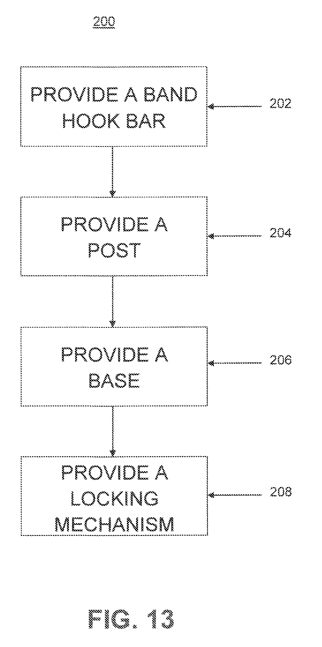
[0089] FIG. 13 is a flow-chart illustrating an example of a method 200 for producing an exercise apparatus. One of skill in the art will appreciate that the method 200 can produce an exercise apparatus, such as exercise apparatus 5 of FIG. 1; however the method 200 is not limited to the exercise apparatus 5 of FIG. 1.
[0090] FIG. 13 shows that the method 200 can include providing 202 a band hook bar. In at least one implementation, the band hook bar can include one or more hook loops. In at least one implementation, the one or more hook loops is to allow the user to releasably attach exercise bands to the band hook bar via the anchor clip. In particular, the hook loops protrude from the band hook bar to provide for attachment points for the exercise bands. In at least one implementation, the band hook bar can include five hook loops.
[0091] FIG. 13 also shows that the method 200 can include providing 204 a post. In at least one implementation, the post is configured to support the band hook bar. In particular, the post can support the weight of the band hook bar and can prevent the band hook bar from moving while the user is exercising. Additionally or alternatively, the post can be configured to allow the user to adjust the position of the band hook bar relative to the post. In particular, the band hook bar can include a collar which is configured to allow the band hook bar to move freely relative to the post until locked in with a locking pin.
[0092] FIG. 13 also shows that the method 200 can include providing 206 a base. In at least one implementation, the base can add mass to the entire resistance exercise apparatus. The additional mass imparted by the base can stabilize the exercise apparatus while the exercise apparatus is being used by a user. Additionally or alternatively, the extra mass imparted by base can allow the exercise apparatus to provide the necessary resistance for the user to perform a proper exercise routine.
[0093] In at least one implementation, the base can be shaped in such a way as to allow the user an unobstructed exercise space in front of the exercise apparatus. In addition, the base can be shaped to allow the exercise apparatus to be placed in a storage position. In particular, the base can be substantially U shaped. For example, the base will have an inside width of about 32 inches, outside width of about 40 inches and a depth of about 42 inches. Additionally or alternatively, the base can be other shapes that allow the base to perform its intended functions.
[0094] FIG. 13 further shows that the method 200 can include providing 208 a locking mechanism. In at least one implementation, the locking mechanism can allow the post to move relative to the base. In particular, the locking mechanism can allow the post to move between one or more exercise positions and a storage position. For example, the post can be oriented perpendicular to the plane of the base, which can allow a user to exercise. Additionally or alternatively, the post can be oriented parallel to the plane of the base, which can allow the exercise apparatus to be stored when not in use.
[0095] In at least one implementation, the locking mechanism can include a locking plate that includes a notch. In addition, the locking mechanism can include a spring loaded pin handle that is configured to interact with the notch to prevent movement of the post relative to the base. For example, the spring loaded pin can include a handle and the notch can be configured to receive a portion of the handle preventing movement of the spring loaded pin, and, by extension, the post, relative to the locking mechanism and the post.
[0096] One skilled in the art will appreciate that, for this and other processes and methods disclosed herein, the functions performed in the processes and methods may be implemented in differing order. Furthermore, the outlined steps and operations are only provided as examples, and some of the steps and operations may be optional, combined into fewer steps and operations, or expanded into additional steps and operations without detracting from the essence of the disclosed embodiments.
[0097] The present invention may be embodied in other specific forms without departing from its spirit or essential characteristics. The described embodiments are to be considered in all respects only as illustrative and not restrictive. The scope of the invention is, therefore, indicated by the appended claims rather than by the foregoing description. All changes which come within the meaning and range of equivalency of the claims are to be embraced within their scope.
* * * * *
D00000
D00001
D00002
D00003
D00004
D00005
D00006
D00007
D00008
D00009
D00010
D00011
D00012
D00013
D00014
D00015
D00016
XML
uspto.report is an independent third-party trademark research tool that is not affiliated, endorsed, or sponsored by the United States Patent and Trademark Office (USPTO) or any other governmental organization. The information provided by uspto.report is based on publicly available data at the time of writing and is intended for informational purposes only.
While we strive to provide accurate and up-to-date information, we do not guarantee the accuracy, completeness, reliability, or suitability of the information displayed on this site. The use of this site is at your own risk. Any reliance you place on such information is therefore strictly at your own risk.
All official trademark data, including owner information, should be verified by visiting the official USPTO website at www.uspto.gov. This site is not intended to replace professional legal advice and should not be used as a substitute for consulting with a legal professional who is knowledgeable about trademark law.