Golf Club Head
Takahashi; Hiroshi ; et al.
U.S. patent application number 12/652783 was filed with the patent office on 2010-12-30 for golf club head. Invention is credited to Hideo Matsunaga, Fumiaki Sato, Hiroshi Takahashi.
| Application Number | 20100331103 12/652783 |
| Document ID | / |
| Family ID | 43381350 |
| Filed Date | 2010-12-30 |


| United States Patent Application | 20100331103 |
| Kind Code | A1 |
| Takahashi; Hiroshi ; et al. | December 30, 2010 |
GOLF CLUB HEAD
Abstract
A golf club head includes a hollow head main body provided with a recess portion in a sole portion thereof; a gravity center characteristic adjusting portion with a plate shape disposed in the recess portion between a center part of the recess portion and a part of a surrounding wall of the recess portion; and a fixing portion for fixing the gravity center characteristic adjusting portion onto the hollow head main body at an arbitrary rotational position.
| Inventors: | Takahashi; Hiroshi; (Saitama, JP) ; Sato; Fumiaki; (Saitama, JP) ; Matsunaga; Hideo; (Saitama, JP) |
| Correspondence Address: |
Kazunao Kubotera;KUBOTERA & ASSOCIATES, LLC
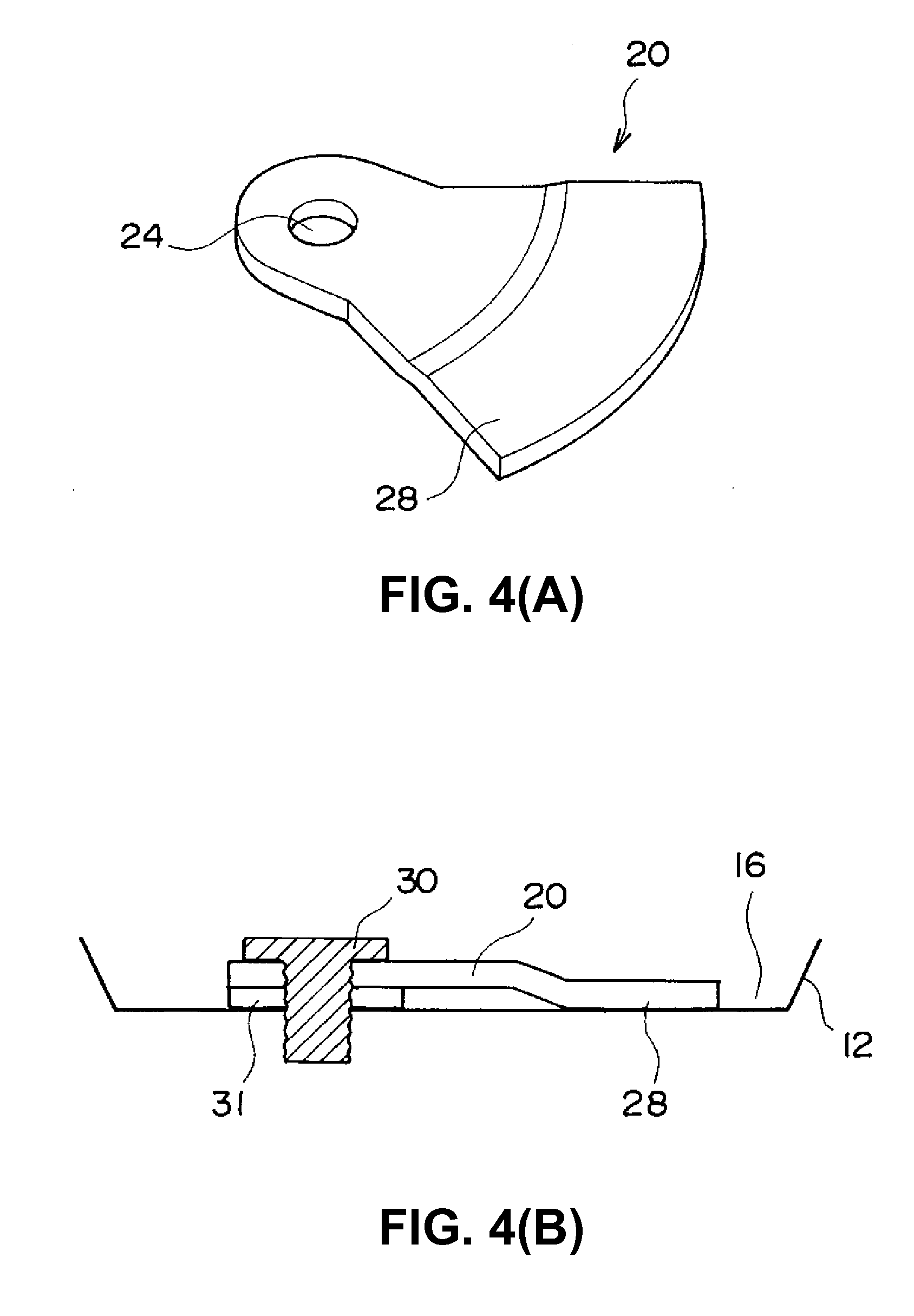
Suite 202, 200 Daingerfield Road
Alexandria
VA
22314
US
|
| Family ID: | 43381350 |
| Appl. No.: | 12/652783 |
| Filed: | January 6, 2010 |
| Current U.S. Class: | 473/338 ; 473/345; 473/349 |
| Current CPC Class: | A63B 2053/0491 20130101; A63B 53/0433 20200801; A63B 60/02 20151001; A63B 53/0466 20130101 |
| Class at Publication: | 473/338 ; 473/345; 473/349 |
| International Class: | A63B 53/06 20060101 A63B053/06; A63B 53/04 20060101 A63B053/04 |
Foreign Application Data
| Date | Code | Application Number |
|---|---|---|
| Jun 29, 2009 | JP | 2009-153807 |
Claims
1. A golf club head comprising: a head main body having a recess portion in a sole portion thereof; a gravity center characteristic adjusting portion disposed in the recess portion; and a fixing portion for fixing the gravity center characteristic adjusting portion onto the hollow head main body at an arbitrary rotational position.
2. The golf club head according to claim 1, wherein said gravity center characteristic adjusting portion includes a screw insertion hole, said fixing portion includes a male screw portion having a head portion and a shaft portion, and said head main body includes a female screw portion so that the shaft portion is inserted in the screw insertion hole to engage the female screw portion.
3. The golf club head according to claim 1, further comprising an anti-rotation mechanism, said anti-rotation mechanism including a protruding portion formed on one of the head main body and the gravity center characteristic adjusting portion, and an engaging groove formed in the other of the head main body and the gravity center characteristic adjusting portion for engaging the protruding portion.
4. The golf club head according to claim 1, further comprising a rib disposed in the recess portion.
Description
BACKGROUND OF THE INVENTION AND RELATED ART STATEMENT
[0001] The present invention relates to a golf club head capable of adjusting a gravity center thereof.
[0002] Patent Reference discloses a conventional golf club head whose gravity center position is changeable. The conventional golf club head disclosed in Patent Reference has a recess portion behind a ball hitting face thereof. The recess portion has a diameter equal to or larger than a diameter of a golf ball. The conventional golf club head also includes a movable weight for adjusting a gravity center position thereof by moving the movable weight outward and inward inside the recess portion.
[0003] Patent Reference: Japanese Patent Publication No. 2006-101918
[0004] In the conventional golf club head disclosed in Patent Reference, the recess portion with a size at least the same as that of the golf ball is provided behind the ball hitting face, and the movable weight is disposed inside the recess portion. Accordingly, the conventional golf club head has an unusual shape.
[0005] In view of the problem described above, an object of the present invention is to provide a golf club head capable of adjusting a gravity center position without having an unusual shape.
[0006] Further objects and advantages of the invention will be apparent from the following description of the invention.
SUMMARY OF THE INVENTION
[0007] In order to attain the object described above, according to a first aspect of the present invention, a golf club head includes a hollow head main body provided with a recess portion in a sole portion thereof; a gravity center characteristic adjusting portion with a plate shape disposed in the recess portion between a center part of the recess portion and a part of a surrounding wall of the recess portion; and a fixing portion for fixing the gravity center characteristic adjusting portion onto the hollow head main body at an arbitrary rotational position.
[0008] In the first aspect of the present invention, the golf club head includes the recess portion in the sole portion of the hollow head main body, and the gravity center characteristic adjusting portion with the plate shape is disposed in the recess portion. Further, the fixing portion is provided for fixing the gravity center characteristic adjusting portion with the plate shape onto the head main body at an arbitrary rotational position, so that a position of the gravity center of the golf club head is adjusted. Therefore, it is possible to change the position of the gravity center without forming the golf club head in an unusual shape.
[0009] According to a second aspect of the present invention, in the golf club head in the first aspect, the gravity center characteristic adjusting portion may have a screw insertion hole at a position corresponding to the center of the recess portion of the head main body. The fixing portion is formed of a male screw portion having a head portion and a shaft portion, and a screw thread is formed on an outer circumference of the shaft portion. A female screw portion is provided at the center of the recess portion of the head main body. The gravity center characteristic adjusting portion is placed inside the recess portion of the head main body, and the shaft portion of the fixing portion is inserted into the screw insertion hole and engages the female screw portion. Accordingly, it is possible to fix the gravity center characteristic adjusting portion onto the head main body at an arbitrary rotational position.
[0010] According to a third aspect of the present invention, the golf club head may include an anti-rotation mechanism. The anti-rotation mechanism includes a protruding portion formed on one of the head main body and the gravity center characteristic adjusting portion, and an engaging groove formed in the other of the head main body and the gravity center characteristic adjusting portion for engaging the protruding portion. Accordingly, it is possible to prevent the gravity center characteristic adjusting portion fixed onto the head main body from rotating when the golf club is swung.
[0011] According to a fourth aspect of the present invention, the golf club head may be provided with a rib on a back side (a side of a hollow portion) of the recess portion formed in the sole portion of the head main body. With the rib, it is possible to improve an impact sound produced when a ball is hit. More specifically, the recess portion disposed in the sole portion of the head main body has a substantially flat bottom. Accordingly, the golf club head tends to be deformed and the impact sound tends to be low when the golf club head hits a ball. With the rib, it is possible to increase a rigidity of the golf club head, thereby improving the impact sound.
[0012] In the golf club head of the present invention, it is possible to adjust the position of the gravity center without having an unusual shape.
BRIEF DESCRIPTION OF THE DRAWINGS
[0013] FIG. 1 is a bottom view showing a golf club head viewed from a sole side thereof according to a first embodiment of the present invention;
[0014] FIG. 2 is a sectional view showing the golf club head taken along a projected line II-II in FIG. 1 according to the first embodiment of the present invention;
[0015] FIGS. 3(A) and 3(B) are views showing an example No. 1 of a gravity center characteristic adjusting portion of the golf club head according to the first embodiment of the present invention, wherein FIG. 3(A) is a perspective view thereof and FIG. 3(B) is a schematic sectional view thereof in a state that the gravity center characteristic adjusting portion is fixed onto a head main body;
[0016] FIGS. 4(A) and 4(B) are views showing an example No. 2 of the gravity center characteristic adjusting portion of the golf club head according to the first embodiment of the present invention, wherein FIG. 4(A) is a perspective view thereof and FIG. 4(B) is a schematic sectional view thereof in the state that the gravity center characteristic adjusting portion is fixed onto the head main body;
[0017] FIGS. 5(A) and 5(B) are views showing an example No. 3 of the gravity center characteristic adjusting portion of the golf club head according to the first embodiment of the present invention, wherein FIG. 5(A) is a perspective view thereof and FIG. 5(B) is a schematic sectional view thereof in the state that the gravity center characteristic adjusting portion is fixed onto the head main body;
[0018] FIG. 6 is a perspective view showing a fixing portion or a male screw portion of the golf club head according to the first embodiment of the present invention;
[0019] FIG. 7 is a perspective view showing a cover of the golf club head according to the first embodiment of the present invention;
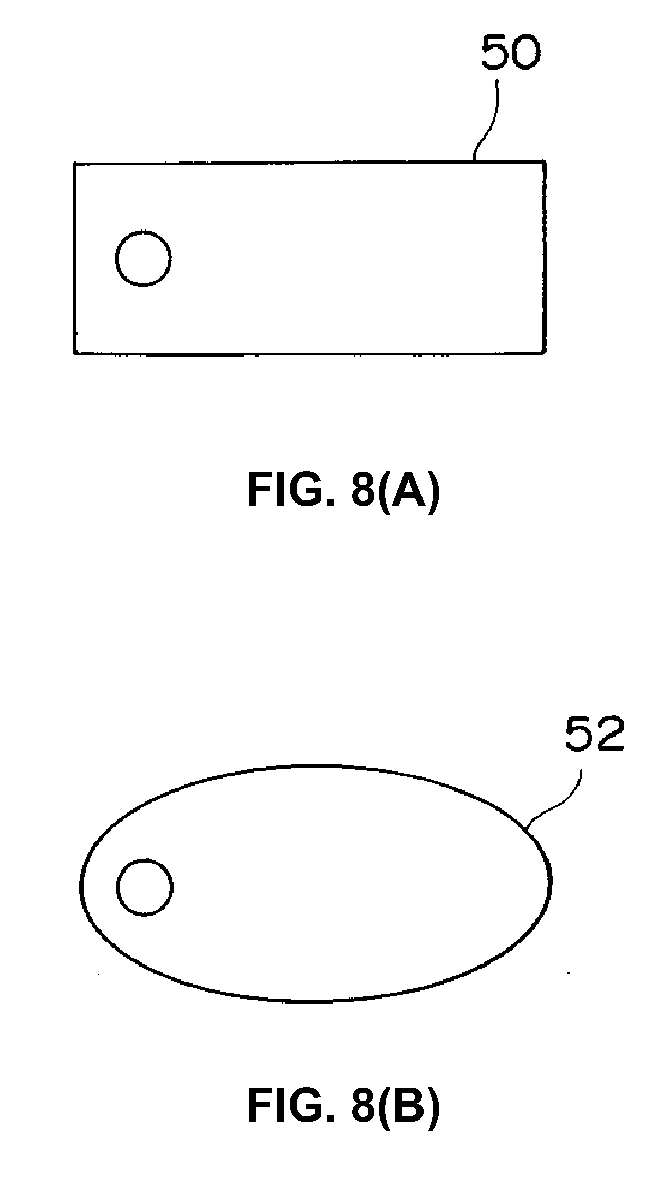
[0020] FIG. 8(A) is a schematic plan view showing a gravity center characteristic adjusting portion of a golf club head according to a second embodiment of the present invention;
[0021] FIG. 8(B) is a schematic plan view showing another gravity center characteristic adjusting portion of the golf club head according to the second embodiment of the present invention;
[0022] FIG. 9 is a schematic view showing an anti-rotation mechanism of a gravity center characteristic adjusting portion according to a third embodiment of the present invention; and
[0023] FIG. 10 is a partial cutout perspective view showing a golf club head having ribs on a back side of a recess portion disposed in a sole portion of a head main body according to a fourth embodiment of the present invention.
DETAILED DESCRIPTION OF PREFERRED EMBODIMENTS
[0024] Hereunder, embodiments of the present invention will be explained with reference to the accompanying drawings.
First Embodiment
[0025] A first embodiment of the present invention will be explained. FIGS. 1 and 2 show a golf club head 10 according to the first embodiment of the present invention. FIG. 1 is a bottom view showing the golf club head 10 viewed from a sole side thereof, and FIG. 2 is a sectional view taken along a projected line II-II in FIG. 1.
[0026] As shown in FIGS. 1 and 2, the golf club head 10 is provided with a head main body 12. The head main body 12 includes a hollow portion 14. A recess portion 16 with a substantially circular shape is disposed in a sole portion of the head main body 12. A female screw portion 18 with a hole shape is provided in the recess portion 16 of the head main body 12 at a center thereof.
[0027] There is no limitation to a material of the head main body 12. For example, fiber reinforced resins and metals such as titanium, a titanium alloy, stainless steel, aluminum, an aluminum alloy, a beryllium copper alloy and a magnesium alloy may be used to form the head main body 12.
[0028] As shown in FIGS. 1 and 2, a gravity center characteristics adjusting portion 20 is disposed in the recess portion 16 of the head main body 12. The gravity center characteristic adjusting portion 20 is a substantially fan-shaped plate and disposed between the center and a part of a surrounding wall 22 of the recess portion 16 of the head main body 12. The gravity center characteristic adjusting portion 20 has a screw insertion hole 24 at a position corresponding to the center of the recess portion 16 of the head main body 12.
[0029] There is no limitation to a material of the gravity center characteristic adjusting portion 20. For example, metals such as tungsten, a tungsten alloy, stainless steel, aluminum, and an aluminum alloy may be used for producing the gravity center characteristic adjusting portion 20. Also, plastics such as a polyester and a nylon may be used. The gravity center characteristic adjusting portion 20 is preferred to have a specific gravity from 0.9 to 19.3.
[0030] In the embodiment, the gravity center characteristic adjusting portion 20 may have configurations shown in FIGS. 3(A), 3(B), 4(A), 4(B), 5(A), and 5(B). In FIGS. 3(B), 4(B), and 5(B), a cover 36 (explained later) is omitted.
[0031] FIGS. 3(A) and 3(B) are views showing an example No. 1 of the gravity center characteristic adjusting portion 20 of the golf club head 10 according to the first embodiment of the present invention.
[0032] In the example No. 1 shown in FIGS. 3(A) and 3(B), the gravity center characteristic adjusting portion 20 has a ring-shaped convex portion 26 formed around the screw insertion hole 24. The convex portion 26 abuts at a bottom thereof against a bottom surface of the recess portion 16 of the head main body 12. Accordingly, even if the bottom surface of the recess portion 16 is curved to a certain extent, the gravity center characteristic adjusting portion 20 can be securely fixed onto the head main body 12. Further, a fan-shaped part of the gravity center characteristic adjusting portion 20 formed at one end thereof does not touch the bottom surface of the recess portion 16, so that the gravity center characteristic adjusting portion 20 can rotate smoothly.
[0033] FIGS. 4(A) and 4(B) are views showing an example No. 2 of the gravity center characteristic adjusting portion 20 of the golf club head 10 according to the first embodiment of the present invention.
[0034] In the example No. 2 shown in FIGS. 4(A) and 4(B), the gravity center characteristic adjusting portion 20 has a fan-shaped bent portion 28 at one side thereof. A bottom surface of the bent portion 28 abuts against the bottom surface of the recess portion 16. Accordingly, the gravity center characteristic adjusting portion 20 can be securely fixed onto the head main body 12, even if the bottom surface of the recess portion 16 is curved to a certain extent. Further, a washer 31 is disposed between the gravity center characteristic adjusting portion 20 and the bottom surface of the recess portion 16. Accordingly, when the gravity center characteristic adjusting portion 20 is attached to the head main body 12, a base end portion of the gravity center characteristic adjusting portion 20 becomes parallel to the bottom surface of the recess portion 16.
[0035] FIGS. 5(A) and 5(B) are views showing an example No. 3 of the gravity center characteristic adjusting portion 20 of the golf club head 10 according to the first embodiment of the present invention.
[0036] In the example No. 3 shown in FIGS. 5(A) and 5(B), the gravity center characteristic adjusting portion 20 is entirely formed in a flat shape. The gravity center characteristic adjusting portion 20 abuts against the bottom surface of the recess portion 16 of the head main body 12 over an entire surface thereof. With the configuration described above, the gravity center characteristic adjusting portion 20 contacts with the recess portion 16 in a large area. Accordingly, the gravity center characteristic adjusting portion 20 can be securely fixed onto the head main body 12.
[0037] In the embodiment, a fixing portion or a male screw portion 30 fixes the gravity center characteristic adjusting portion 20 onto the head main body 12 at an arbitrary rotational position. As shown in FIG. 6, the fixing portion 30 has a head portion 32 and a shaft portion 34, and a screw thread is formed on an outer circumference of the shaft portion 34. There is no limitation to a material of the fixing portion 30. For example, metals such as stainless steel, aluminum, an aluminum alloy, titanium, a titanium alloy and a magnesium alloy may be used for producing the fixing portion 30. Also, plastics such as a polyester and a nylon may be used.
[0038] In the embodiment, the cover 36 is disposed between the head portion 32 of the fixing portion 30 and the gravity center characteristic adjusting portion 20. As shown in FIG. 7, the cover 36 includes a base plate 40 having a substantially ring shape. The base plate 40 includes a screw insertion hole 38 at a center thereof, and protruding portions 42 on one side thereof. The cover 36 is provided for preventing the gravity center characteristic adjusting portion 20 from rotating due to a shock of hitting a ball. There is no limitation to a material of the cover 30. For example, metals such as stainless steel, aluminum, an aluminum alloy, titanium, a titanium alloy and a magnesium alloy may be used for producing the cover 30. Also, plastics such as a polyester and a nylon may be used.
[0039] In the embodiment, when the golf club head 10 is assembled, first, the gravity center characteristic adjusting portion 20 is placed inside the recess portion 16 of the head main body 12. Next, the cover 36 is placed on the gravity center characteristic adjusting portion 20. Then, the shaft portion 34 of the fixing portion 30 is sequentially inserted into both the screw insertion hole 38 of the cover 36 and the screw insertion hole 24 of the gravity center characteristic adjusting portion 20. Lastly, the shaft portion 34 is screwed into the female screw portion 18 by turning the head portion 32 of the fixing portion 30 with a tool. Accordingly, it is possible to fix the gravity center characteristic adjusting portion 20 onto the head main body 12 at an arbitrary rotational position.
Second Embodiment
[0040] A second embodiment of the present invention will be explained. FIG. 8(A) is a schematic plan view showing a gravity center characteristic adjusting portion 50 of the golf club head 10 according to the second embodiment of the present invention. FIG. 8(B) is a schematic plan view showing a gravity center characteristic adjusting portion 52 of the golf club head 10 according to the second embodiment of the present invention.
[0041] As shown in FIG. 8(A), the gravity center characteristic adjusting portion 50 has a rectangular shape. As shown in FIG. 8(B), the gravity center characteristic adjusting portion 52 has an oval shape.
Third Embodiment
[0042] A third embodiment of the present invention will be explained. FIG. 9 is a schematic view showing an anti-rotation mechanism of a gravity center characteristic adjusting portion 72 according to the third embodiment of the present invention.
[0043] As shown in FIG. 9, the gravity center characteristic adjusting portion 72 is fixed to a head main body 68. The head main body 68 has engaging grooves 70, and the gravity center characteristic adjusting portion 72 has a protruding portion 74 for engaging one of the engaging grooves 70. The engaging grooves 70 and the protruding portion 74 constitute the anti-rotation mechanism. When the protruding portion 74 engages one of the engaging grooves 70, it is possible to prevent the gravity center characteristic adjusting portion 72 disposed on the head main body 68 from rotating.
[0044] In the embodiment, alternatively, the head main body 68 may have a protruding portion, and the gravity center characteristic adjusting portion 72 may have engaging grooves for engaging the protruding portion. The number of the protruding portion and the engaging grooves may be arbitrary.
Fourth Embodiment
[0045] A fourth embodiment of the present invention will be explained. FIG. 10 is a partial cutout perspective view showing a golf club head having ribs 80 on a back side of a recess portion 78 disposed in a sole portion of a head main body 76 according to the fourth embodiment of the present invention.
[0046] As shown in FIG. 10, the head main body 76 has the ribs 80 with an arbitrary shape at the back side of the recess portion 78 (a side of a hollow portion) disposed in the sole portion of the head main body 76. When the ribs 80 are formed in the head main body 76, it is preferable that the ribs 80 have a uniform height. Accordingly, when a gravity center characteristic adjusting portion is disposed in the recess portion 78, it is possible to easily rotate the gravity center characteristic adjusting portion.
[0047] In the embodiment, with the ribs 80, it is possible to improve an impact sound produced when a ball is hit. More specifically, the recess portion 78 disposed in the sole portion of the head main body 76 has a substantially flat bottom. Accordingly, the golf club head tends to be deformed and the impact sound tends to be low when the golf club head hits a ball. With the ribs 80, it is possible to increase rigidity of the golf club head, thereby improving the impact sound.
[0048] The disclosure of Japanese Patent Application No. 2009-153807, filed on Jun. 29, 2009 is incorporated in the application by reference.
[0049] While the invention has been explained with reference to the specific embodiments of the invention, the explanation is illustrative and the invention is limited only by the appended claims.
* * * * *
D00000
D00001
D00002
D00003
D00004
D00005
D00006
D00007
D00008
D00009
D00010
XML
uspto.report is an independent third-party trademark research tool that is not affiliated, endorsed, or sponsored by the United States Patent and Trademark Office (USPTO) or any other governmental organization. The information provided by uspto.report is based on publicly available data at the time of writing and is intended for informational purposes only.
While we strive to provide accurate and up-to-date information, we do not guarantee the accuracy, completeness, reliability, or suitability of the information displayed on this site. The use of this site is at your own risk. Any reliance you place on such information is therefore strictly at your own risk.
All official trademark data, including owner information, should be verified by visiting the official USPTO website at www.uspto.gov. This site is not intended to replace professional legal advice and should not be used as a substitute for consulting with a legal professional who is knowledgeable about trademark law.