Toy vehicle rotational element for rotating a toy vehicle
Carlson; Gabriel ; et al.
U.S. patent application number 12/660239 was filed with the patent office on 2010-12-30 for toy vehicle rotational element for rotating a toy vehicle. This patent application is currently assigned to JAKKS Pacific, Inc.. Invention is credited to Michael Bernstein, Gabriel Carlson, Dion Fields, Dominic Laurienzo.
| Application Number | 20100330874 12/660239 |
| Document ID | / |
| Family ID | 43381254 |
| Filed Date | 2010-12-30 |


| United States Patent Application | 20100330874 |
| Kind Code | A1 |
| Carlson; Gabriel ; et al. | December 30, 2010 |
Toy vehicle rotational element for rotating a toy vehicle
Abstract
Described is a toy vehicle track set and, more particularly, a rotational element for use with a track set that is operable for rotating a toy vehicle. The rotational element includes an anchor for attaching the rotational element with a surface. A flip box is operatively connected with the anchor, and the flip box is formed to receive a toy vehicle and rotate the toy vehicle. A track connector connects a toy vehicle track with the rotational element, such that the toy vehicle engages the track and is propelled from the flip box along the track. The flip box is spring-loaded, and entrance of the toy vehicle into the flip box causes a spring element to be released and the flip box to rotate the toy vehicle and return the toy vehicle back onto the track. In a desired aspect, the track is a string.
| Inventors: | Carlson; Gabriel; (Los Angeles, CA) ; Laurienzo; Dominic; (Los Angeles, CA) ; Fields; Dion; (Thousand Oaks, CA) ; Bernstein; Michael; (Hermosa Beach, CA) |
| Correspondence Address: |
    TOPE-MCKAY & ASSOCIATES
    30765 PACIFIC COAST HIGHWAY #420
    MALIBU
    CA
    90265
    US
|
| Assignee: | JAKKS Pacific, Inc. Malibu CA |
| Family ID: | 43381254 |
| Appl. No.: | 12/660239 |
| Filed: | February 22, 2010 |
Related U.S. Patent Documents
| Application Number | Filing Date | Patent Number | ||
|---|---|---|---|---|
| 61208161 | Feb 21, 2009 | |||
| 61208490 | Feb 25, 2009 | |||
| Current U.S. Class: | 446/446 |
| Current CPC Class: | A63H 18/026 20130101; A63H 18/00 20130101 |
| Class at Publication: | 446/446 |
| International Class: | A63H 18/00 20060101 A63H018/00 |
Claims
1. A toy vehicle rotational element for rotating a toy vehicle, comprising: an anchor for attaching the rotational element with a surface; a flip box, wherein the flip box is formed to receive a toy vehicle and rotate the toy vehicle; and a track connector for connecting a track with the rotational element, such that the toy vehicle engages the track and is propelled from the flip box along the track.
2. The toy vehicle rotational element as set forth in claim 1, wherein the flip box is formed to be spring-loaded, such that rotation of the flip box induces extension of a spring element connected with the flip box, and wherein entrance of the toy vehicle into the flip box causes the spring element to be released and the flip box to rotate.
3. The toy vehicle rotational element as set forth in claim 2, further comprising a flip box housing connecting the flip box with the anchor.
4. The toy vehicle rotational element as set forth in claim 3, wherein the flip box comprises at least one cut-out therein to provide clearance for a flywheel of the toy vehicle to engage the track.
5. The toy vehicle rotational element as set forth in claim 4, wherein the track connector is attached with the flip box housing.
6. The toy vehicle rotational element as set forth in claim 5, wherein the track is a string.
7. The toy vehicle rotational element as set forth in claim 1, wherein the flip box comprises at least one cut-out therein to provide clearance for a flywheel of the toy vehicle to engage the track.
8. The toy vehicle rotational element as set forth in claim 1, wherein the track is a string.
9. The toy vehicle rotational element as set forth in claim 1, further comprising a flip box housing connecting the flip box with the anchor.
10. The toy vehicle rotational element as set forth in claim 1, wherein the track connector is attached with the flip box housing.
11. A method for forming a toy vehicle rotational element for rotating a toy vehicle, comprising acts of: forming an anchor for attaching the rotational element with a surface; forming a flip box, wherein the flip box is formed to receive a toy vehicle and rotate the toy vehicle; and forming a track connector for connecting a track with the rotational element, such that the toy vehicle engages the track and is propelled from the flip box along the track.
12. The method for forming the toy vehicle rotational element as set forth in claim 11, further comprising an act of forming the flip box to be spring-loaded, such that rotation of the flip box induces extension of a spring element connected with the flip box, and wherein entrance of the toy vehicle into the flip box causes the spring element to be released and the flip box to rotate.
13. The method for forming the toy vehicle rotational element as set forth in claim 12, further comprising an act of forming a flip box housing connecting the flip box with the anchor.
14. The method for forming the toy vehicle rotational element as set forth in claim 13, further comprising an act of forming the flip box to have at least one cut-out therein to provide clearance for a flywheel of the toy vehicle to engage the track.
15. The method for forming the toy vehicle rotational element as set forth in claim 14, further comprising an act of attaching the track connector with the flip box housing.
16. The method for forming the toy vehicle rotational element as set forth in claim 15, wherein the track is a string.
17. The method for forming the toy vehicle rotational element as set forth in claim 11, further comprising an act of forming the flip box to have at least one cut-out therein to provide clearance for a flywheel of the toy vehicle to engage the track.
18. The method for forming the toy vehicle rotational element as set forth in claim 11, further comprising an act of forming a flip box housing connecting the flip box with the anchor.
19. The method for forming the toy vehicle rotational element as set forth in claim 11, further comprising an act of attaching the track connector with the flip box housing.
20. The method for forming the toy vehicle rotational element as set forth in claim 11, wherein the track is a string.
Description
PRIORITY CLAIM
[0001] This is a Non-Provisional patent application of U.S. Provisional Application No. 61/208,161 filed in the United States on Feb. 21, 2009, titled, "Toy Vehicle Rotational Element for Rotating a Toy Vehicle." This application is also a Non-Provisional patent application of U.S. Provisional Application No. 61/208,490 filed in the United States on Feb. 25, 2009, titled, "Toy Vehicle Launcher."
BACKGROUND OF THE INVENTION
[0002] (1) Field of Invention
[0003] The present invention relates to a toy vehicle track set and, more particularly, to a rotational element for use with a track set that is operable for rotating a toy vehicle.
[0004] (2) Description of Related Art
[0005] Track sets for use with toy vehicles have long been known in the art. Conventional track sets use a length of track upon which a toy vehicle is placed and rolled along. Some improvements upon such traditional track sets include obstacles and, in some cases, ramps. In such cases, the ramps are typically positioned at the end of the track to allow the vehicle to enter the ramp and then become airborne upon exiting the ramp. Alternatively, obstacles are used to allow the toy vehicle to maneuver through or otherwise interact with the obstacles. While these track sets provide enjoyment and a certain level of interaction, they all require that the toy vehicle continue along a length of track. In other words, existing track sets do not provide for a mechanism by which the toy vehicle is manipulated to immediately return on the same track from which it came.
[0006] Thus, a continuing need exists for a mechanism or device for use with a track set that is operable for immediately returning a toy vehicle to the same track from which it came.
SUMMARY OF INVENTION
[0007] The present invention relates to a toy vehicle track set and, more particularly, to a rotational element for use with a track set that is operable for rotating a toy vehicle. The rotational element includes an anchor for attaching the rotational element with a surface. A flip box is operatively connected with the anchor, and the flip box is formed to receive a toy vehicle and rotate the toy vehicle. The rotational element further comprises a track connector for connecting a track with the rotational element, such that the toy vehicle engages the track and is propelled from the flip box along the track.
[0008] In another aspect, the flip box is formed to be spring-loaded, such that rotation of the flip box induces extension of a spring element connected with the flip box, and wherein entrance of the toy vehicle into the flip box causes the spring element to be released and the flip box to rotate and propel the toy vehicle from the flip box.
[0009] In another aspect, the toy vehicle rotational element further comprises a flip box housing connecting the flip box with the anchor.
[0010] In yet another aspect, the flip box comprises at least one cut-out therein to provide clearance for a flywheel of the toy vehicle to engage the track.
[0011] In another aspect, the track connector is attached with the flip box housing.
[0012] In another aspect, the track is a string.
[0013] Finally, the present invention also includes a method for forming and using the device described herein. The method for forming the device includes a plurality of acts of forming and attaching the said components to arrive at the described device. Alternatively, the method for using the device includes a plurality of acts of using the device as described herein.
BRIEF DESCRIPTION OF THE DRAWINGS
[0014] The objects, features and advantages of the present invention will be apparent from the following detailed descriptions of the various aspects of the invention in conjunction with reference to the following drawings, where:
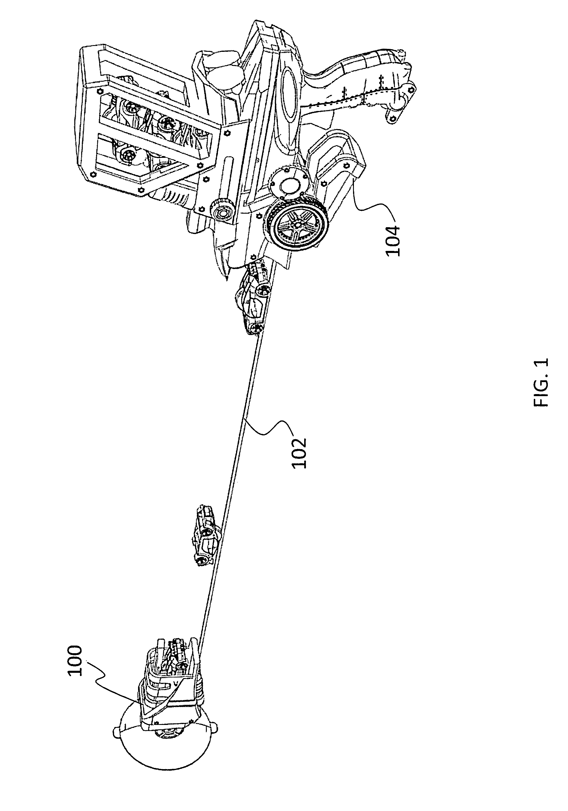
[0015] FIG. 1 is an illustration of a toy vehicle rotational element according to the present invention, depicting the rotational element as connected with a string;
[0016] FIG. 2 is an illustration of an example of a toy vehicle for use with the rotational element of the present invention;
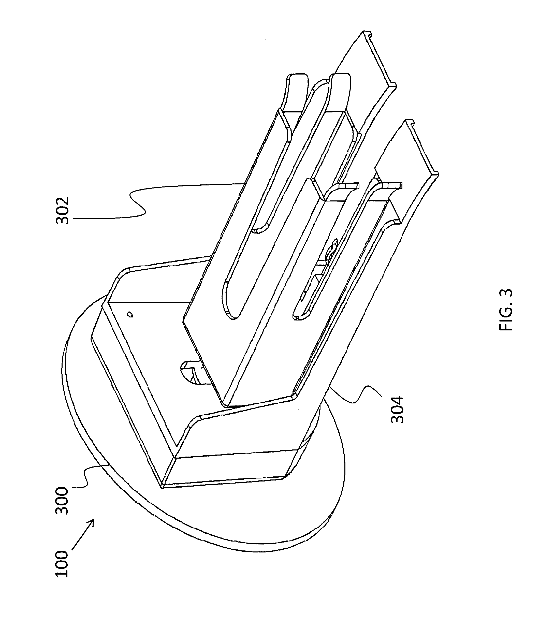
[0017] FIG. 3 is a side, perspective-view illustration of a toy vehicle rotational element according to the present invention;
[0018] FIG. 4 is a side-view illustration of a toy vehicle rotational element according to the present invention;
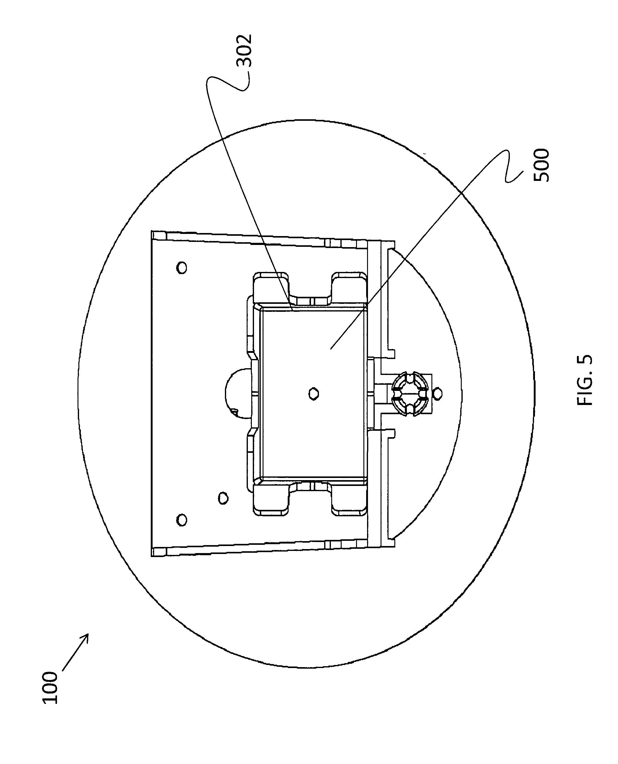
[0019] FIG. 5 is a front-view illustration of a toy vehicle rotational element according to the present invention;
[0020] FIG. 6 is a top-view illustration of a toy vehicle rotational element according to the present invention; and
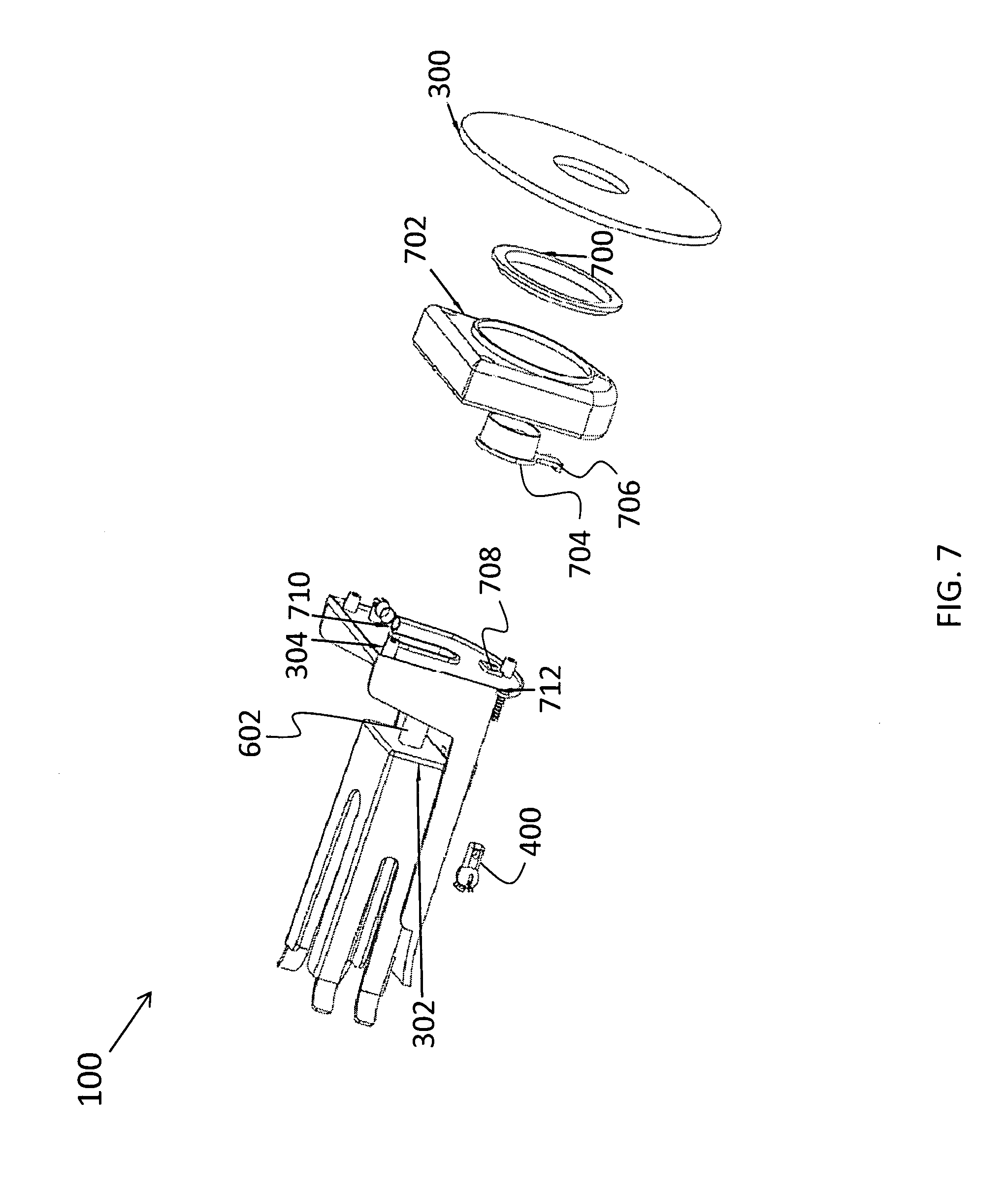
[0021] FIG. 7 is an exploded-view illustration of a toy vehicle rotational element according to the present invention.
DETAILED DESCRIPTION
[0022] The present invention relates to a toy vehicle track set and, more particularly, to a rotational element for use with a track set that is operable for rotating a toy vehicle. The following description is presented to enable one of ordinary skill in the art to make and use the invention and to incorporate it in the context of particular applications. Various modifications, as well as a variety of uses in different applications will be readily apparent to those skilled in the art, and the general principles defined herein may be applied to a wide range of embodiments. Thus, the present invention is not intended to be limited to the embodiments presented, but is to be accorded the widest scope consistent with the principles and novel features disclosed herein.
[0023] In the following detailed description, numerous specific details are set forth in order to provide a more thorough understanding of the present invention. However, it will be apparent to one skilled in the art that the present invention may be practiced without necessarily being limited to these specific details. In other instances, well-known structures and devices are shown in block diagram form, rather than in detail, in order to avoid obscuring the present invention.
[0024] The reader's attention is directed to all papers and documents which are filed concurrently with this specification and which are open to public inspection with this specification, and the contents of all such papers and documents are incorporated herein by reference. All the features disclosed in this specification, (including any accompanying claims, abstract, and drawings) may be replaced by alternative features serving the same, equivalent or similar purpose, unless expressly stated otherwise. Thus, unless expressly stated otherwise, each feature disclosed is one example only of a generic series of equivalent or similar features.
[0025] Furthermore, any element in a claim that does not explicitly state "means for" performing a specified function, or "step for" performing a specific function, is not to be interpreted as a "means" or "step" clause as specified in 35 U.S.C. Section 112, Paragraph 6. In particular, the use of "step of" or "act of" in the claims herein is not intended to invoke the provisions of 35 U.S.C. 112, Paragraph 6.
[0026] Please note, if used, the labels left, right, front, back, top, bottom, forward, reverse, clockwise and counter clockwise have been used for convenience purposes only and are not intended to imply any particular fixed direction. Instead, they are used to reflect relative locations and/or directions between various portions of an object.
[0027] (1) Description
[0028] The present invention relates to a rotational element for use with a track set that is operable for rotating a toy vehicle. The rotational element is formed to rotate (e.g., flip) a toy vehicle at the end of a track and replace the toy vehicle upon the track so that it returns in the direction from which it came. In other words, the rotational element is positioned at the end of a track such that when the toy vehicle enters the rotational element, it flips the toy vehicle which causes it to exit the rotational element and return on the track in the direction that it initially came from.
[0029] As shown in FIG. 1, the rotational element 100 can be connected with a track 102. The track 102 can be a conventional track or any other suitable track upon which a toy vehicle can travel, a non-limiting example of which includes a string (as shown in FIG. 1). In one aspect as shown, the track 102 (e.g., string) is connected to a launcher 104 that shoots the toy vehicle along the track 102 and into the rotational element 100. The track 102 is connected to the rotational element 100 through any suitable mechanism, depending on the type of track 102. Non-limiting examples of mechanisms by which the track 102 is connected to the rotational element include a snap-fit mechanism and a thread and screw configuration.
[0030] The rotational element is formed to operate with a mobile toy vehicle, a non-limiting example of which includes a die-cast 1:64 toy vehicle. A non-limiting example is illustrated in FIG. 2, where the rotational element is formed to operate with a toy vehicle 200 that includes a flywheel 202 (or a traditional toy vehicle without a flywheel). The flywheel 202 extends through an aperture of the bottom of the toy vehicle 200, and at least a portion of the flywheel 202 extends through an aperture of the top portion of the toy vehicle 200. The portion of the flywheel 202 which extends through the aperture of the bottom portion is able to contact a surface below the toy vehicle 200 to propel the toy vehicle 200. The surface can either be a ground surface or a track. As a non-limiting example, the flywheel 202 includes an indentation around its circumference that allows it to run along a thin track (e.g., string).
[0031] The flywheel 202 is powered through any suitable mechanism or device, a non-limiting example of which includes a rip cord 204 that is connectable with a gear attached with the flywheel 202. The rip cord 204 includes a set of teeth 206 along at least one side and is removably inserted inside the toy vehicle 200 to induce rotation of the flywheel 202. The rip cord 204 induces rotation of the flywheel 202 by interlocking with at least a portion of the flywheel 202 or an axle inserted through the flywheel 202. For example, a gear with teeth can be attached with the axle and exposed for engagement with the rip cord 204. Alternatively, if a launcher 104 is used (as shown in FIG. 1), the launcher 104 may include a direct drive system that includes a drive wheel that engages with the flywheel 202 when the toy vehicle 200 is loaded into the launcher 104. It should be understood that the toy vehicle 200 requires an intrinsic power means (e.g., the flywheel 202) to propel the toy vehicle 200 across a surface. It is the intrinsic power means that drives the toy vehicle 200 into the rotational element and from the rotational element.
[0032] FIGS. 3 through 10 illustrate various views of the rotational element 100. As shown in FIG. 3, the rotational element 100 includes an anchor 300 for attaching the rotational element 100 with a surface. The anchor 300 is any suitable mechanism or device for affixing the rotational element 100 with a surface, non-limiting examples of which include a suction cup mechanism, a clamp mechanism, an adhesive (e.g., glue), weld, or fastener for fastening the rotational element 100 with another object, device, or surface (e.g., wall). As can be appreciated by one skilled in the art, the anchor 300 may be either detachably attached or permanently attached with the rotational element 100.
[0033] The rotational element 100 also comprises an elongated flip box 302. The flip box 302 is operably connected with the anchor 300 (via a housing, rotator, or any other suitable mechanism or device). As a non-limiting example, and as illustrated in FIG. 3, the rotational element includes a flip box housing 304, which connects the flip box 302 with the anchor 300. The flip box housing 304 stabilizes the flip box 302 and also provides a means of attachment to the anchor 300.
[0034] In a desired aspect, the flip box 302 is sized and shaped to receive the toy vehicle and turn the toy vehicle upside down. As noted above, the toy vehicle may include a flywheel that protrudes from the toy vehicle on both the bottom and top sides of the toy vehicle. Thus, when the toy vehicle is rotated upside down, the flywheel that previously protruded from the top of the toy vehicle now protrudes from the bottom of the toy vehicle to engage the surface and drive the toy vehicle from the flip box 302 and back down the track.
[0035] Furthermore, the flip box 302 is formed to be spring-loaded. Thus, the flip box 302 is connected with the anchor 300 through a spring mechanism. The flip box 302 can be rotated 180 degrees (or any other suitable rotation), at which point the flip box 302 is locked into a loaded position, wherein a bias element (e.g., spring element) is extended (i.e., stretched). When the toy vehicle enters the flip box 302, it causes the flip box 302 to be compressed and released from the loaded (extended) position and thereby rotate (i.e., flip) 180 degrees to its original position. In rotating, the flip box 302 effectively flips the toy vehicle 180 degrees so that the directional momentum of the flywheel, or other intrinsic power means, is now rotated 180 degrees to cause the toy vehicle to drive from the flip box 302 and return on the track. The flip box 302 is released from the loaded position using any suitable mechanism or device, a non-limiting example of which includes a trigger mechanism or a locking cam that is released through compression of the flip box 302. For instance, the mechanism may include a latch connected with a lock (e.g., cam lock) that is activated and then released when the toy vehicle impacts the back end of the flip box 302. This impact pushes the latch off of the lock and allows the spring to release, thereby flipping the toy vehicle and returning it to the track in an upside-down orientation.
[0036] FIG. 4 depicts a side-view of the rotational element 100. As shown in FIG. 4, the rotational element 100 includes a track connector 400 below the flip box 302, which is depicted as protruding from the flip box housing 304. A non-limiting example of a track connector 400, as illustrated in FIG. 4, is a quick disconnect socket. However, as can be appreciated by one skilled in the art, the track connector 400 can be connected with the flip box 302, flip box housing 304, or anchor 300, either directly or indirectly, through any suitable mechanism or device. The track connector 400 is formed to allow a user to easily connect a track (e.g., string) with the rotational element 100. As can be appreciated by one skilled in the art, the rotational element 100 can include any suitable track connector 400 for connection with a variety of types of tracks, non-limiting examples of which include a snap-fit mechanism and a thread and screw configuration. Additionally, if the track is a string, the string may simple be tied to the track connector 400.
[0037] FIG. 5 illustrates a front-view of the rotational element 100. As is depicted in this view, the flip box 302 includes a cavity 500 formed to receive a toy vehicle. FIG. 6 is a top-view illustration of the rotational element 100. As described above, in a desired aspect the rotational element 100 is formed to be used with a toy vehicle that includes a flywheel which extends through an aperture of the bottom of the toy vehicle. In order to accommodate the flywheel of such a toy vehicle, both the flip box 302 and the flip box housing 304 have an elongated cut-out 600 therein to provide clearance for the flywheel to contact the track, which is connected with the rotational element 100 through the track connector 400. Additionally, a flip box shaft 602 is shown in this view. In a desired aspect, the flip box shaft 602 is a component of the flipping mechanism. The flip box shaft 602 is connected with the flip box 302 as part of the mechanism which allows the flip box 302 to rotate as will be described in detail below.
[0038] FIG. 7 is an exploded-view illustration of the rotational element 100. As shown, the rotational element 100 includes an anchor 300 (shown as a suction cup) for attachment to a surface (e.g., wall). It should be understood that the present invention can also be a part of a larger playset, such that the rotational element is integrally molded with or attached to the larger playset. In such an aspect, the anchor 300 could be considered the integrally molded connection (or screws, etc.) that attaches the rotational element 100 to the larger playset.
[0039] However, as depicted, an attachment ring 700 is used to connect the anchor 300 to an attachment housing 702. Additionally, the attachment housing 702 includes a flip box arm 704 having a latch element 706. The latch element 706 is engageable with a locking element 708 on the flip box housing 304. A bias element 710 (e.g., a spring element) is also attached with the flip box housing 304. When the flip box 302 is rotated 180 degrees into a loaded position, the bias element 710 is extended and the latch element 706 engages the locking element 708. In one aspect, as shown in FIG. 7, the flip box 302 is connected with the flip box arm 704 (such as through the flip box shaft 602), such that when a toy vehicle strikes the back of the flip box 302, the flip box 302 is driven forward causing the latch element 706 to be released (i.e., pop out) from the locking element 708. The bias element 710 is then able to rotate the flip box 302 due to a connection between the bias element 710 and the latch element 706 when the rotational element 100 is fully assembled. Thus, the release of the bias element 710 (i.e., compression of the spring element) allows 180 degree rotation of the flip box 302 about the major axis of the flip box shaft 602. The toy vehicle inside the flip box 302 then lands back on the attached track (e.g., string) in the opposite orientation (i.e., upside-down). As shown, a screw 712 attaches the track connector with the flip box housing 304.
* * * * *
D00000
D00001
D00002
D00003
D00004
D00005
D00006
D00007
XML
uspto.report is an independent third-party trademark research tool that is not affiliated, endorsed, or sponsored by the United States Patent and Trademark Office (USPTO) or any other governmental organization. The information provided by uspto.report is based on publicly available data at the time of writing and is intended for informational purposes only.
While we strive to provide accurate and up-to-date information, we do not guarantee the accuracy, completeness, reliability, or suitability of the information displayed on this site. The use of this site is at your own risk. Any reliance you place on such information is therefore strictly at your own risk.
All official trademark data, including owner information, should be verified by visiting the official USPTO website at www.uspto.gov. This site is not intended to replace professional legal advice and should not be used as a substitute for consulting with a legal professional who is knowledgeable about trademark law.