Simulated Pupil Assembly And Simulated Eye Using Same
Chen; Shun-Yi
U.S. patent application number 12/547501 was filed with the patent office on 2010-12-30 for simulated pupil assembly and simulated eye using same. This patent application is currently assigned to HON HAI PRECISION INDUSTRY CO., LTD.. Invention is credited to Shun-Yi Chen.
| Application Number | 20100330870 12/547501 |
| Document ID | / |
| Family ID | 43381252 |
| Filed Date | 2010-12-30 |


| United States Patent Application | 20100330870 |
| Kind Code | A1 |
| Chen; Shun-Yi | December 30, 2010 |
SIMULATED PUPIL ASSEMBLY AND SIMULATED EYE USING SAME
Abstract
The present disclosure provides a simulated pupil assembly. The simulated pupil assembly includes a substrate, a number of blades, and a driving device. The substrate includes a number of rotation portions arranged in a circular. The blades are arranged to sequentially overlap each other to cooperatively form a dome, and the blades at one side of the substrate. The blades include a number of linking end rotatably mounted to the corresponding the rotation portions, a number of distal ends cooperatively defines a hole. The driving device is to the substrate and the blades. The driving device is configured for driving the blades to rotate toward or away from the substrate to contract or dilate the hole of the blades.
| Inventors: | Chen; Shun-Yi; (Tu-Cheng, TW) |
| Correspondence Address: |
    Altis Law Group, Inc.;ATTN: Steven Reiss
    288 SOUTH MAYO AVENUE
    CITY OF INDUSTRY
    CA
    91789
    US
|
| Assignee: | HON HAI PRECISION INDUSTRY CO.,
LTD. Tu-Cheng TW |
| Family ID: | 43381252 |
| Appl. No.: | 12/547501 |
| Filed: | August 26, 2009 |
| Current U.S. Class: | 446/343 |
| Current CPC Class: | A63H 3/40 20130101 |
| Class at Publication: | 446/343 |
| International Class: | A63H 3/40 20060101 A63H003/40 |
Foreign Application Data
| Date | Code | Application Number |
|---|---|---|
| Jun 29, 2009 | CN | 200910303816.0 |
Claims
1. A simulated pupil assembly comprising: a substrate comprising a plurality of rotation portions arranged in a circular; a plurality of blades arranged sequentially overlap each other to cooperatively form a dome, the plurality of blades comprising: a plurality of linking ends rotatably mounted to the corresponding rotation portions; a plurality of distal ends cooperatively defining a hole; a driving device connected to the substrate and the blades, and configured for driving the blades to rotate toward or away from the substrate to contract or dilate the hole of the blades.
2. The simulated pupil assembly as claimed in claim 1, wherein each blade is an arcuate configuration.
3. The simulated pupil assembly as claimed in claim 1, wherein the substrate is a circular plate.
4. The simulated pupil assembly as claimed in claim 3, wherein the substrate comprises four fixing portions extending outwardly from a portion of the circular plate along the radial direction thereof.
5. The simulated pupil assembly as claimed in claim 4, wherein each two adjacent fixing portions are perpendicular to each other.
6. The simulated pupil assembly as claimed in claim 1, wherein the driving device comprising a motor and a transmission mechanism connected between the motor and the blades.
7. The simulated pupil assembly as claimed in claim 1, wherein the blades are made of ferromagnetic material.
8. The simulated pupil assembly as claimed in claim 6, wherein the transmission mechanism comprises a transmission shaft, a circular transmission frame, a center support, and a hinge, the center support is connected between the circular transmission frame and the transmission shaft, and the hinge is connected between the transmission shaft and the motor.
9. The simulated pupil assembly as claimed in claim 1, wherein the simulated pupil assembly further comprises a motor, a magnetic spring received in a receiving space formed between the blades and the substrate, and four cables connected the motor to the magnetic spring via four cable through holes formed on the substrate.
10. The simulated pupil assembly as claimed in claim 6, wherein the simulated pupil assembly further comprises a plurality of elastic elements connected the blades to the substrate.
11. A simulated eye comprising: an simulated eyeball assembly defining a receiving space, a first hole communicated with the receiving space, and a fixing structure extended from an inner surface thereof toward to the center of the receiving space and formed opposite to the first hole; a simulated pupil assembly received in the receiving space and facing the first hole, the simulated pupil assembly comprising: a substrate attached to the inner surface of the simulated eyeball assembly, the substrate comprising a plurality of rotation portions arranged in a circular; a plurality of blades arranged sequentially overlap each other to cooperatively form a dome, and the plurality of blades comprising: a plurality of linking ends rotatably mounted to the corresponding rotation portions; a plurality of distal ends cooperatively defining a hole facing the first hole of the simulated eyeball assembly; a driving device connected to the substrate and the blades, and fixed on the fixing structure, the driving device being configured for driving the blades to rotate toward or away from the substrate to contract or dilate the hole of the blades.
12. The simulated eye as claimed in claim 11, wherein each blade is an arcuate configuration.
13. The simulated eye as claimed in claim 11, wherein the substrate is a circular plate.
14. The simulated eye as claimed in claim 13, wherein the substrate comprises four fixing portions extending outwardly from a portion of the circular plate along the radial direction thereof.
15. The simulated eye as claimed in claim 14, wherein each two adjacent fixing portions are perpendicular to each other, and the plurality of rotation portions is formed throughout the circular plate.
16. The simulated eye as claimed in claim 11, wherein the driving device comprising a motor and a transmission mechanism connected between the motor and the blades.
17. The simulated eye as claimed in claim 11, wherein the blades are made of ferromagnetic material.
18. The simulated eye as claimed in claim 16, wherein the transmission mechanism comprises a transmission shaft, a circular transmission frame, a center support, and a hinge, the center support is connected between the circular transmission frame and the transmission shaft, and the hinge is connected between the transmission shaft and the motor.
19. The simulated eye as claimed in claim 11, wherein the simulated pupil assembly further comprises a motor, a magnetic spring received in a receiving space formed between the blades and the substrate, and four cables connected the motor to the magnetic spring via four cable through holes formed on the substrate.
20. The simulated eye as claimed in claim 16, wherein the simulated pupil assembly further comprises a plurality of elastic elements connected the blades to the substrate.
Description
BACKGROUND
[0001] 1. Technical Field
[0002] The present disclosure relates to toys, and more particularly, to a simulated pupil assembly capable of changing the size in a simulated eye using same.
[0003] 2. Description of Related Art
[0004] The size of a person's pupil can dilate or contract according to the person's emotion. The pupil is dilated when a person is terrified or astonished. On the other hand, the pupil is contracted when a person is unpleasable or uninterested.
[0005] Now, various dolls and animated plush type toys as known can imitate human and/or animal characteristics. In such toys, various efforts have been made to simulate the eyes of human or animal. Some dolls only have plastic button eyes. And some simulated eyes are painted on the face of the dolls. However, the eyes of such toys are toneless, and can not change the size of the pupils to express lively expression.
[0006] What is needed, therefore, is a simulated pupil assembly capable of changing the size in a simulated eye using same to overcome or at least alleviate the above-described problem.
BRIEF DESCRIPTION OF THE DRAWING
[0007] Many aspects of the present simulated pupil assembly and a simulated eye using the same can be better understood with reference to the following drawing. The components in the drawing are not necessarily drawn to scale, the emphasis instead being placed upon clearly illustrating the principles of the present simulated pupil assembly and a simulated eye using same.
[0008] FIG. 1 is a schematic view of a simulated eye according to a first exemplary embodiment.
[0009] FIG. 2 is a schematic, cross-sectional view of the simulated eye, taken along line II-II of FIG. 1.
[0010] FIG. 3 is an exploded view of a simulated pupil assembly of the simulated eye of FIG. 1.
[0011] FIG. 4 is an assembled view of the simulated pupil assembly of FIG. 3.
[0012] FIG. 5 is a schematic, cross-sectional view of the simulated eye of FIG. 2, showing the pupil dilated.
[0013] FIG. 6 is a schematic, cross-sectional view of a simulated eye according to a second exemplary embodiment.
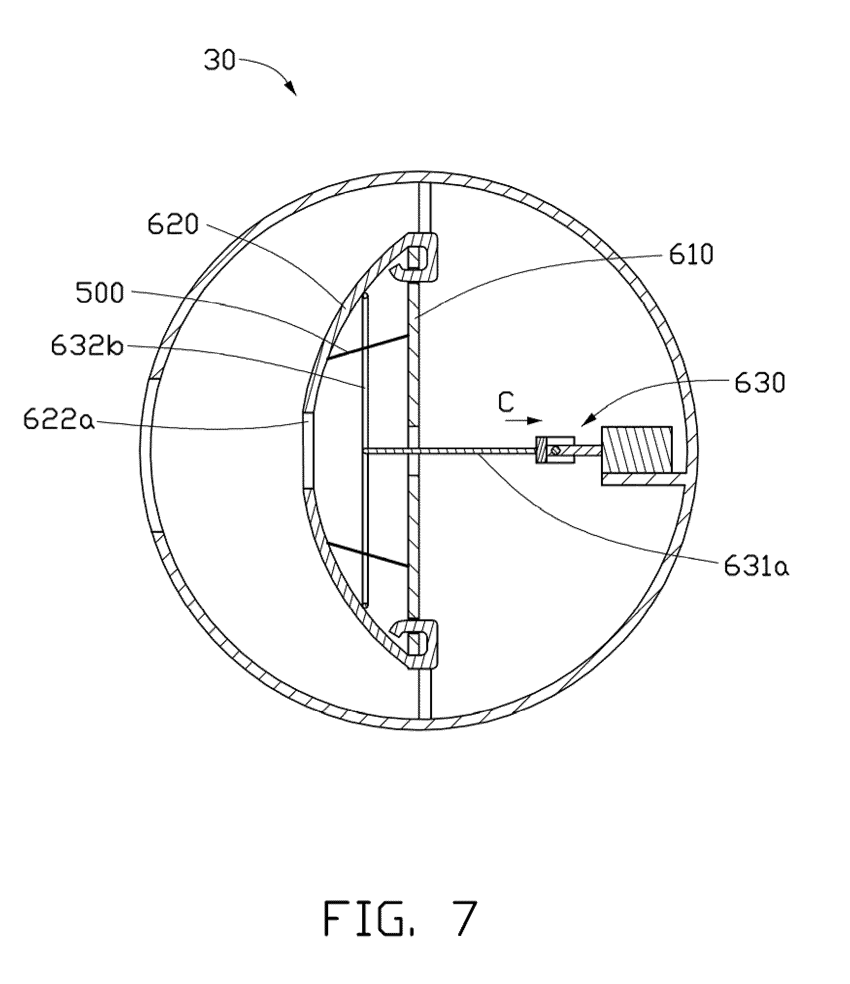
[0014] FIG. 7 is a schematic, cross-sectional view of a simulated eye according to a third exemplary embodiment.
DETAILED DESCRIPTION
[0015] Embodiments of the present disclosure will now be described in detail below, with reference to the accompanying drawings.
[0016] Referring to FIGS. 1 and 2, a simulated eye 10, according to a first exemplary embodiment, is shown. The simulated eye 10 includes a simulated eyeball assembly 100 and an simulated pupil assembly 200.
[0017] The simulated eyeball assembly 100 is a ball-shaped configuration. The simulated eyeball assembly 100 defines a receiving space 110 and a first circular through hole 120. The simulated eyeball assembly 100 includes an outer surface 130 and an inner surface 140. The color of the outer surface 130 is white. The first circular through hole 120 communicates with the receiving space 110. A fixing structure 141 extends from the inner surface 140 opposite to the first circular through hole 120 toward to a center of the receiving space 110.
[0018] The simulated pupil assembly 200 is received in the receiving space 110 facing the first circular through hole 120. The simulated pupil assembly 200 includes a substrate 210, a number of blades 220 engaged with the substrate 210, and a driving device 230 engaged with the substrate 210 and the blades 220. In the present embodiment, the pupil assembly 200 has eighteen blades 220.
[0019] Referring to FIGS. 3 and 4, the substrate 210 includes four fixing portions 211 and a circular plate 215. The circular plate 215 includes a first surface 215a, a second surface 215b opposite to the first surface 215a, and a sidewall 215c. The first surface 215a faces the first circular through hole 120. The four fixing portions 211 extend outwardly from a portion of the circular plate 215 along the radial direction. An angle between adjacent fixing portions 211 is 90 degrees. The four fixing portions 211 extends equidistantly around the inner surface 140 on a same plane passing through the center of the simulated eyeball assembly 100 parallel the first circular through hole 120, thus forming a front receiving room 111 and a back receiving room 112 (Seen in FIG. 2). The first circular through hole 120 communicates with the front receiving room 111. The fixing structure 141 is received in the back receiving room 112.
[0020] The circular plate 215 defines an aperture 215d, a number of rectangular slots 215e, and a number of rotation portions 215f. The aperture 215d is formed in a center of the circular plate 215. The number of rectangular slots 215e are aligned equidistantly around the aperture 215d in the surface adjacent the sidewall 215c of the circular plate 215. The number of rotation portions 215f are formed corresponding to the rectangular slots 215e on the cylindrical surface. A center axis OO' is defined passing through the center of the center hole 215d. The rotation portion 215f also can be a sleeve. In the present embodiment, the center axis of each rotation portion 215f is perpendicularly to the center axis OO'. In the present embodiment, the simulated pupil assembly 200 has eighteen rectangular slots 215e and eighteen rotations portions 215f corresponding to the rectangular slots 215e.
[0021] The blade 220 is an arcuate configuration. The blades 220 can be made from plastic or metal material. In the present embodiment, the blades 220 are made from ferromagnetic material such as nickel or iron. Each blade 220 includes a linking end 221, a distal end 222, and an outside surface 223. The linking end 221 can be a rotating shaft or a sleeve. In the present embodiment, the linking end 221 is a sleeve. The linking end 221 is rotatably mounted to the corresponding rotation portion 215f. In the present embodiment, the color of the outside surface 223 is blue. When the linking end 221 is rotatably mounted to the corresponding rotation portion 215f, thereby the eighteen blades 220 are arranged to sequentially overlap each other to cooperatively form a dome. The distal ends 222 cooperatively define a second hole 222a. When the blades 220 rotate about the rotation portions 215f toward or away from the substrate 210, the diameter of the second hole 222a will be corresponding contracted or dilated. In the present embodiment, the second hole 222a is coaxial to the first circular through hole 120.
[0022] Referring to FIGS. 3 and 5, the driving device 230 includes a motor 231 and a transmission mechanism 232. The motor 231 is fixed on the fixing structure 141. The motor 231 can be a rotary motor or a linear motor. In the present embodiment, the motor 231 is a linear motor. The motor 231 includes a motor shaft 231a.
[0023] The transmission mechanism 232 is connected the motor 231 to the blades 220. The transmission mechanism 232 includes a transmission shaft 232a, a circular transmission frame 232b, a center support 232c, and a hinge 232d. The center support 232c lies on a diameter of the circular transmission frame 232b. The center support 232c is connected the transmission shaft 232a to the circular transmission frame 232b. The transmission shaft 232a is connected to the motor shaft 231a through the hinge 232d. The circular transmission frame 232b is received in a space formed between the blades 220 and the substrate 210. In the present embodiment, the circular transmission frame 232b is magnetic. When the motor shaft 231a moves along a direction A of the center axis OO', the blades 220 are driven magnetically to move in the A direction, as a result the second hole 222a of the simulated pupil assembly 200 is dilated. Similarly, when the motor shaft 231 a moves along an inverted direction of the center axis OO', the blades 220 are driven magnetically to move in the inverted direction of A direction, as a result the second hole 222a of the simulated pupil assembly 200 is contracted. The circular transmission frame 232b can also be a non-magnetic substance. With the above configuration, the simulated pupil assembly 200 is capable of changing the size of the second hole 222a. .
[0024] Referring to FIG. 6, an simulated eye 20, according to a second exemplary embodiment, is shown. The simulated eye 20 of the second embodiment is similar to the simulated eye 10 of the first embodiment, except for the structure of the simulated eyeball assembly 300, the driving device 430, and the substrate 410. Four cable through holes 413 are defined on the substrate 410. The driving device 430 includes a motor 431, four cables 432, and a magnetic spring 433. The magnetic spring 433 is received in a receiving space formed between the blades 420 and the substrate 410. The magnetic spring 433 includes opposite ends 433a, 433b. The end 433a attracts the blades 420, and the end 433b is attached to the substrate 410. The end 432a of the cable 432 is fastened on the end 433a through the cable through hole 413. The ends 432b of the four cables 432 are fasten on the motor 431 via a motor shaft 431a thereof.
[0025] When the motor shaft 431a moves along a direction B of the center axis OO', the magnetic spring 433 is constricted, the blades 420 are driven magnetically to move in the B direction, as a result the simulated eye 20 looks have a smaller pupil. Otherwise, when the motor shaft 431a moves along an inverted direction of the center axis OO', the blades 420 are driven magnetically to move in the inverted direction of the B direction, as a result the simulated eye 20 looks have a larger pupil.
[0026] Referring to FIG. 7, a simulated eye 30, according to a third exemplary embodiment, is shown. In this embodiment, the circular transmission frame 632b and the blades 620 is made of plastic. The simulated eye 30 further includes a number of elastic elements 500 connected the blades 620 to the substrate 610. A pull force is applied on the elastic element 500. In the present embodiment, the elastic elements 500 are elastic bands. The blades 620 are pressed on the circular transmission frame 632b through the elastic elements 500, and moves together with the circular transmission frame 632b. When a motor shaft 63 la moves along a C direction of the center axis OO', the blades 620 are driven elastically to move in the C direction, as a result the simulated eye 30 looks have a smaller pupil. Otherwise, when the motor shaft 631a moves along an inverted direction of the center axis OO', the blades 620 are driven elastically to move in the inverted direction of the C direction, as a result the simulated eye 30 looks have a larger pupil.
[0027] While certain embodiments have been described and exemplified above, various other embodiments will be apparent to those skilled in the art from the foregoing disclosure. The present disclosure is not limited to the particular embodiments described and exemplified, and the embodiments are capable of considerable variation and modification without departure from the scope of the appended claims.
* * * * *
D00000
D00001
D00002
D00003
D00004
D00005
D00006
D00007
XML
uspto.report is an independent third-party trademark research tool that is not affiliated, endorsed, or sponsored by the United States Patent and Trademark Office (USPTO) or any other governmental organization. The information provided by uspto.report is based on publicly available data at the time of writing and is intended for informational purposes only.
While we strive to provide accurate and up-to-date information, we do not guarantee the accuracy, completeness, reliability, or suitability of the information displayed on this site. The use of this site is at your own risk. Any reliance you place on such information is therefore strictly at your own risk.
All official trademark data, including owner information, should be verified by visiting the official USPTO website at www.uspto.gov. This site is not intended to replace professional legal advice and should not be used as a substitute for consulting with a legal professional who is knowledgeable about trademark law.