Test Device For Platelet Aggregation Detection
Rendu; Francine ; et al.
U.S. patent application number 12/738795 was filed with the patent office on 2010-12-30 for test device for platelet aggregation detection. This patent application is currently assigned to CENTRE NATIONAL DE LA RECHERCHE SCIENTIFIQUE. Invention is credited to Daniel Fruman, Jaime Levenson, Francine Rendu.
| Application Number | 20100330605 12/738795 |
| Document ID | / |
| Family ID | 39167008 |
| Filed Date | 2010-12-30 |


| United States Patent Application | 20100330605 |
| Kind Code | A1 |
| Rendu; Francine ; et al. | December 30, 2010 |
TEST DEVICE FOR PLATELET AGGREGATION DETECTION
Abstract
The invention relates to the test device for platelet aggregation detection comprising:--an element (1) for receiving a blood sample--a capillary tube (3) connected at a first end (31) to said element (1) and at a second end (32) to a pressure lowering device (5) to pump said blood sample through said capillary tube (3)--at least a pair of facing electrodes (8) on the capillary tube--a device for measuring an impedance between said pair of facing electrodes. The invention also relates to a process for using this device, comprising: a) receiving a blood sample and pumping it through the capillar tube (3) b) determining a dynamic change of the value of the impedance between at least one pair of electrodes (8).
| Inventors: | Rendu; Francine; (Paris, FR) ; Fruman; Daniel; (Le Pecq, FR) ; Levenson; Jaime; (Paris, FR) |
| Correspondence Address: |
    FULBRIGHT & JAWORSKI L.L.P.
    600 CONGRESS AVE., SUITE 2400
    AUSTIN
    TX
    78701
    US
|
| Assignee: | CENTRE NATIONAL DE LA RECHERCHE
SCIENTIFIQUE Paris FR |
| Family ID: | 39167008 |
| Appl. No.: | 12/738795 |
| Filed: | October 16, 2008 |
| PCT Filed: | October 16, 2008 |
| PCT NO: | PCT/IB2008/003346 |
| 371 Date: | July 8, 2010 |
| Current U.S. Class: | 435/29 ; 435/287.1 |
| Current CPC Class: | Y10T 436/11 20150115; Y10T 436/25375 20150115; G01N 27/07 20130101; G01N 33/4905 20130101 |
| Class at Publication: | 435/29 ; 435/287.1 |
| International Class: | C12Q 1/02 20060101 C12Q001/02; C12M 1/34 20060101 C12M001/34 |
Foreign Application Data
| Date | Code | Application Number |
|---|---|---|
| Oct 22, 2007 | EP | 07291282.7 |
Claims
1.-22. (canceled)
23. A test device for platelet aggregation detection comprising: a blood sample receiving element; a capillary tube connected at a first end to said element and adapted to be connected at a second end to a pressure lowering device to pump said blood sample through said capillary tube during use; at least a pair of facing electrodes on the capillary tube; and connecting elements to connect the electrodes to a device for determining a dynamic change of an impedance between said pair of facing electrodes during use.
24. The test device of claim 23, wherein the blood sample receiving element is a needle.
25. The test device of claim 23, wherein a plurality of pairs of electrodes are spread on at least part of the length of the capillary tube.
26. The test device of claim 23, wherein the pressure lowering device is adapted to generate a shear rate .gamma..sub.w of the blood sample in the capillary tube between 200 s.sup.-1 and 1000 s.sup.-1 during use.
27. The test device of claim 26, wherein the shear rate .gamma..sub.w is between 500 s.sup.-1 and 700 s.sup.-1.
28. The test device of claim 27, wherein the shear rate .gamma..sub.w is 600 s.sup.-1.
29. The test device of claim 23, further defined as having a ratio between a length (L) and an internal diameter (D) of: L 2 .pi. / S , ##EQU00002## wherein: S is an internal cross section of the capillary tube; and the ratio is less than or equal to: .DELTA. P 4 .gamma. w .mu. , ##EQU00003## wherein: .gamma..sub.w is a minimal shear rate in s.sup.-1 to be achieved during use; .DELTA.P is a maximal pressure differential between both ends of the capillary tube (in Pa) during use; and .mu. is a viscosity of the sample during use.
30. The test device of claim 29, wherein D is between 100.mu. and 800.mu..
31. The test device of claim 30, wherein D is between 100.mu. and 500.mu..
32. The test device of claim 23, wherein the capillary tube has at least two lengths of different internal cross sections
33. The test device of claim 23, wherein the blood sample receiving element is a blood well.
34. The test device of claim 23, further comprising a reservoir in communication with the second end of the capillary tube.
35. The test device of claim 34, wherein a reservoir in communication with the second end of the capillary tube is mounted on the support.
36. The test device of claim 23, wherein at least the blood sample receiving element, the capillary tube and a connector in electrical connection with said at least one pair of electrodes are mounted on a multi-layer support.
37. A system comprising a test device of claim 23 and of a measurement unit having at least one impedance measuring device coupled to the connecting device.
38. The system of claim 37, wherein the impedance measuring device is a multimeter.
39. The system of claim 37, further comprising a pump coupled to the second end of the capillary tube.
40. The system of claim 37, further comprising an injector adapted to add at least one agent to the blood sample during use.
41. A process comprising: obtaining a test device of claim 23; obtaining a blood sample and pumping it through the capillar tube; and determining a dynamic change of the value of the impedance between at least one pair of electrodes.
42. The process of claim 41, wherein the blood sample has a volume between 100 .mu.l and 1 ml.
43. The process of claim 41, wherein the shear rate of the blood sample in the capillary tube is between 200 s.sup.-1 and 1000 s.sup.-1.
44. The process of claim 43, wherein the shear rate is between 500 s.sup.-1 and 700 s.sup.-1.
45. The process of claim 44, wherein the shear rate is 600 s.sup.-1.
46. The process of claim 41, wherein the impedance is a capacitance C.
47. The process of claim 41, further comprising adding a treatment agent to the sample in incubating the sample.
48. The process of claim 47, wherein the treatment agent is aspirin.
49. The process of claim 41, further comprising adding an aggregation agent to the sample.
50. The process of claim 49, wherein the aggregation agent is collagen.
Description
[0001] The present invention relates to a test device for platelet aggregation detection.
[0002] Numerous test devices for exist in the market to perform such detection. The tests are generally performed in specialized laboratories and require a long time to obtain the results.
[0003] Most known devices require isolation of platelets from the blood which needs the preparation of a sample. Examples are the trombo aggregometers BIOLA (Moscou) or EMA (Servibio) which use a laser to measure optical transmission through isolated platelets.
[0004] Another problem of most known devices is that they require a large amount of blood, for examples those using turbidimetry e.g. a device sold by COULTER (CHRONOLOG) or test devices such as BIOLA or ENTEC MEDICAL, or those using impedance such as another device sold by COULTER or the MULTIPLATE device sold by Instrumentation Laboratory. It is often necessity to dilute the blood samples with an appropriate amount of serum.
[0005] There is a need for a test device that is capable of performing routine and ambulatory test i.e. using full (or whole) blood, and preferably without being obliged to dilute the blood sample, and that is capable of giving quick results to respond to ambulatory conditions or to an emergency condition of a patient.
[0006] A step toward this aim is performed by the PFA 100 of Dade Behring which measures with full blood the occlusion time of a blood flow through an aperture in the center of a which is membrane coated with aggregating molecules such a collagen, and by the more recent device Verify Now sold by ACCUMETRICS. However, these two devices still require a large amount of blood.
[0007] DiaMed has introduced a test by colorimetry in its IMPACT device which can be performed on a small sample of blood (130 .mu.l).
[0008] The present invention relates to a test device that is capable of performing an ambulatory test on a small sample of blood, and more particularly of full blood, and of giving a result in a relatively small amount of time, so that it is suitable for ambulatory or emergency conditions.
[0009] To that effect, the invention relates to a test device for platelet aggregation detection comprising: [0010] an element for receiving a blood sample [0011] a capillary tube connected at a first end to said element and adapted to be connected at a second end to a pressure lowering device to pump said blood sample through said capillary tube [0012] at least a pair of spaced electrodes, namely placed side by side or face to face, on the capillary tube [0013] and a connecting device to connect the electrodes to a device for measuring an impedance between said pair of spaced electrodes.
[0014] The invention also relates to a system comprised of a said test device and of a measurement unit having at least one impedance measuring device, such as a multimeter, coupled to the connecting device. The system may also comprise a pump coupled to the second end of the capillary tube and/or injection means for adding at least one agent to the blood sample.
[0015] The invention also relates to a process for using a test device as defined above, characterized in that it comprises:
[0016] a) receiving a blood sample and pumping it through the capillary tube,
[0017] b) determining a dynamic change of the value of the impedance (capacitance and/or resistance) between at least one pair of spaced electrodes.
[0018] The invention will be better understood with the following description in relation with drawings, wherein.
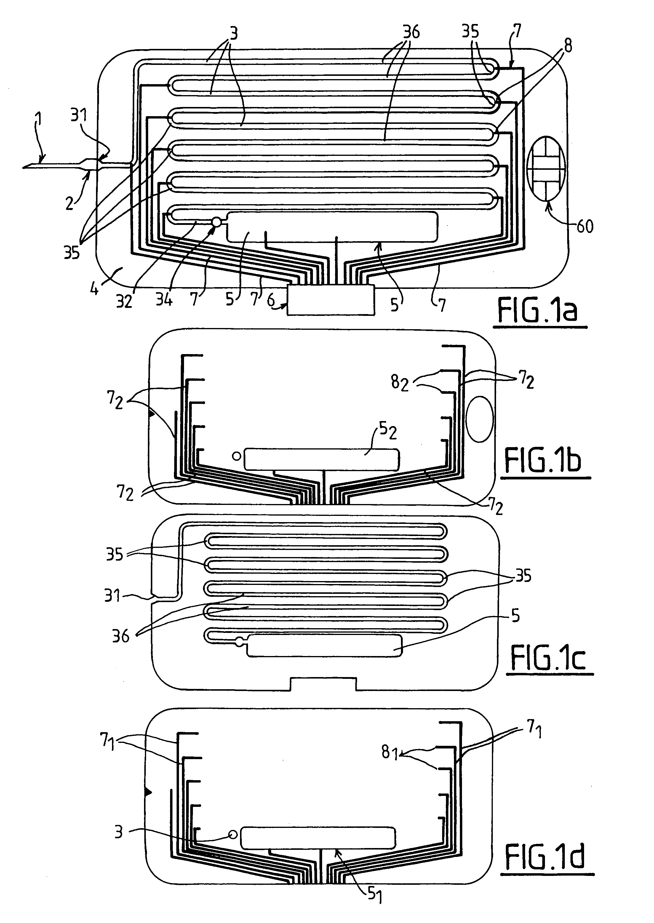
[0019] FIG. 1a told illustrate a first embodiment of a test device according to the invention in top view, respectively of the whole device (1a), and of its top (1b), middle (1c), and bottom (1d) layers.
[0020] FIG. 2 illustrate another multi-layered embodiment of the invention;
[0021] FIG. 3 illustrates a device 110 of the invention connected to a measurement unit 100 having a keyboard 130 and a screen 120,
[0022] FIGS. 4a to 4d illustrate a preferred embodiment for the test device according to the invention, thereof
[0023] FIGS. 5a and 5b illustrate an experimental device and the position of the electrodes of a pair
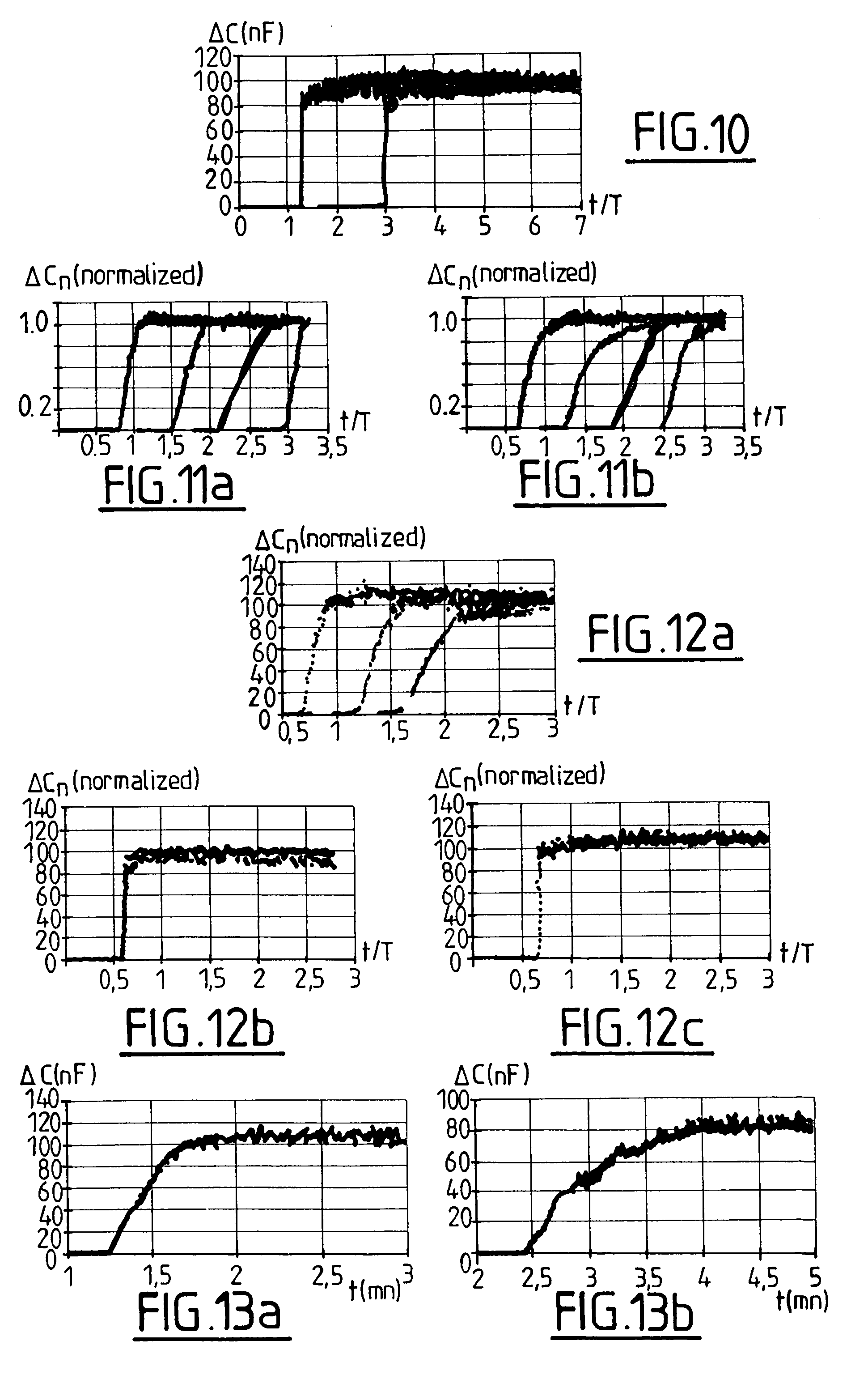
[0024] FIGS. 6 to 10, 11a, 11 b, 12a to 12c, 13a and 13b illustrate test results obtained with a test device according to FIGS. 4a and 4b. Variation .DELTA.C (in nF) of capacitance C or normalized variation .DELTA.C.sub.n of the capacitance is plotted versus time t in minutes or non dimensional time t/T.
[0025] The normalized variation .DELTA.C.sub.n is obtained by the formula:
.DELTA.C.sub.n=.DELTA.C/C.sub.max
[0026] C.sub.max being the maximum value of the capacitance obtained when blood is circulating between the electrodes.
[0027] The test device illustrated in FIGS. 1a to 1d is comprised of a to hypodermic needle 1 connected by a resilient coupler 2 to an end 31 of a capillary tube 3 which extends along a sinuous path on a glass or plastic support 4 that may be of the size of a credit card. The hypodermic needle and the resilient coupler can be replaced by a blood well where one or more drops of blood may be deposited. The capillary extends along a sinuous or concentric path or any other geometry and has a length allowing shearing the blood sample at a chosen shear rate and time. At the other end 32 of the capillary tube 3 a vane 34 is disposed, to allow a connection of the end 32 to a closed reservoir 5 at a pressure lower than atmospheric pressure to create a pressure difference .DELTA.P between both ends 31 and 32 of the capillary tube 3 which forms a micro channel along which a collected blood sample is sucked.
[0028] The blood sample thus circulates between ends 31 and 32 where it occupies a part of the length L of the tube 3 and is collected by the reservoir 5. A support 4 with an integrated reservoir 5 allows a self-contained operation for an in situ or ambulatory test.
[0029] For the best efficiency, it is recommended that reservoir 5 should be at the lowest pressure that would be compatible with the avoidance of degassing of the blood sample, e.g. 30 mmHg, i.e. about 4000 Pa.
[0030] In a variant, a depression or vacuum pump is connected to end 32 of the capillary tube 3, but in this case an integrated reservoir 5 is still desirable to collect the blood, because it allows discarding directly the test device with the blood sample once used.
[0031] A connector 6 is electrically coupled to pairs of metal strips 7 on the support 4 to connect to a measuring equipment pairs of electrodes 8 that are spread along the capillary tube 3, for example as shown in curved regions 35 separating linear portions 36 of the capillary tube 3.
[0032] The connector 6 allows connecting the pairs of electrodes to the equipment to measure the impedance with a set of conventional multimeters, and more particularly the value of the capacitance C between the pairs of electrodes, as will be discussed in the example below.
[0033] It is noted that only a pair of spaced electrodes 8 may be enough. However, using two or more pairs of electrodes 8 along the path of the capillary tube 3 allows obtaining several curves representing the response after subjecting the blood sample to increasing durations of shear, which brings additional information and contributes to the reliability of the test. Two pairs of electrodes may be used to determine the velocity, by determining the time span separating their transient response, and hence the shear rate in the blood sample. With more than two pairs of electrodes, the equipment may comprise only two multimeters: when the measurement starts, the first and second multimeter are coupled to the first and second pairs of electrodes. Then, when the curve representing the passage of blood before the first pair of electrodes has been recorded, the first multimeter is coupled to the third pair of electrodes, and when the curve representing the passage of blood before the second pair of electrodes has been recorded, the second multimeter is coupled to the fourth pair of electrodes and so on.
[0034] As shown in FIG. 1b-1d, the device is comprised of a sandwich of three layers. The bottom layer (FIG. 1d) is e.g.; made of plastic and comprises a first set of strips made of metal or of or conductive ink 7.sub.1 having end electrodes 8.sub.1, an embossed region 5.sub.1 forming the bottom of the reservoir 5, and an optional spot 34 to lodge an obturator for the channel 3. The middle layer (FIG. 1c) is e.g. made of plastic and comprises an engraved channel 3 (e.g. by high speed water jet) and an engraved reservoir 5. The top layer is similar to the bottom layer (strips 7.sub.2, electrodes 8.sub.2 and top region 5.sub.2). It also comprises an optional opening for an electronic chip 60.
[0035] As shown in the variant of FIG. 2, the support 4 may be comprised of several elements namely a bottom layer 4.sub.1 having an aperture 47 forming a reservoir, a first isolating plate 4.sub.2 bearing connecting strips 7, then the main plate 4.sub.0 comprising the capillary tube 3 with its pairs of measurement electrodes 8 and last a top layer 4.sub.3 which protects the plates 4.sub.2 and 4.sub.0 and may comprise a second set of connecting strips.
[0036] In the preferred embodiment of FIGS. 4a-4d, the capillary tube 3' is wound in a helical way, and has a circular, square or rectangular cross section for the circulation of blood. End 32' of the capillary tube 3' in communication with reservoir 5 (FIG. 4c) is located at the center whereas end 31' communicating with the blood well 50 is at the periphery. The volume of this blood well 50 is approximately 30 mm.sup.3 to receive a blood sample. Injection tubes 51 and/or 52 may be provided to inject an aggregation agent.
[0037] The inside diameter of the capillary tube 3' is 300.mu. and its length is 117 cm, to provide a shear rate of about 600.sup.s-1 to a sample of full blood with a difference of pressure .DELTA.P=730 mm Hg (96000 Pa).
[0038] FIG. 4a shows the plate 4.sub.0 in perspective, whereas figure to 4b is a top view of FIG. 4a and FIG. 4c is a cut of FIG. 2c along CC.
[0039] FIG. 4d shows a partial cut along DD and detail G thereof to show a pair of electrodes 8.sub.1 and 8.sub.2.
[0040] Detail G shows two electrodes 8.sub.1 and 8.sub.2 of a pair of electrodes placed side by side and separated by a gap d. For example each electrode occupies part of the perimeter of the tube 3' and has a length l=1 mm and width w=0.3 mm, and the electrodes 8.sub.1 and 8.sub.2 are separated by a distance d=1 mm.
[0041] The tests illustrated in FIGS. 6 to 13b have been performed with an experimental device provided with four pairs of spaced electrodes (8.sub.11, 8.sub.12; 8.sub.21, 8.sub.22; 8.sub.31, 8.sub.32; and 8.sub.41, 8.sub.42) that are part of a common support 70 shown in FIG. 5a, each electrode 8.sub.11 . . . 8.sub.42 having a length l=1 mm and a width w=0.3 mm (see FIG. 5b) and occupying half of the circumference of a capillary tube having an internal diameter of D=300.mu.. The pairs of electrodes are longitudinally spaced by a distance d=1 mm. A supple capillary tube 71 having a chosen length L is disposed to follow a sinuous path and is in contact with the successive pairs of electrodes.
[0042] FIG. 6 illustrates the change AC in the value of the capacitance with two neutral liquids, namely distilled water and a coloured solution, for three pairs of electrodes.
[0043] The passage of the front separating the two liquids produces a sudden variation of the value of the capacitance C. Signals at three pairs of electrodes 1,3 and 4 have been shown.
[0044] FIG. 7 illustrates the change AC with a flow of distilled water followed by 50% diluted blood with an aggregating agent (collagen at 3 .mu.g/ml), with four pairs of electrodes.
[0045] FIG. 8 illustrates a flow of diluted blood that has been incubated during 15 nm with a solution of aspirin at a concentration (5 mM) that is known to inhibit platelet aggregation to which collagen (3 .mu.g/ml) has been added after incubation with signals from three pairs of electrodes 1,2 and 3.
[0046] For this sample, aspirin is efficient to prevent aggregation since the change of .DELTA.C exhibits a sudden variation.
[0047] FIG. 9 illustrates a flow of blood that has been incubated (curve I) during 15 mm with aspirin (5 mM) or not incubated (curve II). It can be seen that curve II (no aspirin added) doesn't show the sudden change of curve I, indicating that platelet aggregation may have occurred in curve II, not in curve I.
[0048] FIG. 10 adresses the specificity of the test with a sample of blood without platelets.
[0049] The passage of the sample produces a fast rise .DELTA.C of the value of the capacitance C, which confirms that when a slow transition is present, it is specific of platelets.
[0050] FIGS. 11a and 11b test the influence of an aggregating agent (collagen) on a sample of diluted blood.
[0051] FIG. 11a shows curves obtained with a sample without addition of collagen and FIG. 11b shows curves with a sample of the same blood with an addition of collagen (3 .mu.g/ml).
[0052] This comparison shows that the main effect is obtained by the shear rate on the sample (around 600 s-.sup.1 in the example) and that the addition of an aggregating agent may not be necessary. The test device according to the invention may thus be used with a sample of full (or diluted) blood with or without addition of an aggregating agent such as collagen.
[0053] FIGS. 12a to 12c show the effect of a treatment with aspirin. FIG. 9a shows the curve before the treatment. FIGS. 9b and 9c show curves after 3 days of treatment (500 mg/day) respectively without addition of collagen to the sample, and with addition of collagen (3 .mu.g/ml). The sharp change of .DELTA.C in FIGS. 9b and 9c indicates an efficiency of the treatment, independently of the presence of collagen.
[0054] FIG. 13a and FIG. 13b show the correspondence between a test with 50% diluted blood (FIG. 13a) and a test with full blood (FIG. 13b). These curves show that the results are consistent and that the test device may be used either with full blood or with diluted blood.
[0055] Tests on full blood are of course preferable for ambulatory or emergency tests. But tests on diluted are also of interest for various reasons, especially since the dilution allows obtaining lower shear rates with the same device.
[0056] Another way of obtaining different values of shear rates is providing the capillary tube with two or more lengths of different cross-section. Pressure measurement at the beginning and at the end of each section allows to determine the value of the shear rate in each cross-section.
[0057] In the test device, the ratio L/D between the length L and an internal diameter D of a circular capillary tube and S being the internal cross-section of a capillary tube:
L / D = L 2 .pi. / S .ltoreq. .DELTA. P 4 .gamma. w .mu. ##EQU00001## [0058] .gamma..sub.W being the minimal shear rate in s.sup.-1, nominally 200 s.sup.-1 [0059] .DELTA.P being the maximal pressure differential between both ends of the capillar tube (in Pa), nominally 10.sup.5 Pa [0060] .mu. viscosity of the sample (nominally 0.003 Pas for a blood sample).
[0061] The shear rate of the blood sample in the capillary tube is for example between 200 s.sup.-1 and 1000 s.sup.-1, more particularly between 500 s.sup.-1 and 700 s.sup.-1, the preferred value being 600 s.sup.-1. Note that the phenomenon of platelet aggregation depends on the shear rate and the above ranges are pertinent. D is for example between 100 .mu.m and 800 .mu.m and preferably between 100 .mu.m and 500 .mu.m.
[0062] The volume of the blood sample is for example between 15 .mu.l and 1 ml (e.g. 100 .mu.l) and it is for example chosen so that the sample occupies only part of the length of the capillary tube.
[0063] The maximal transit time in the capillary tube is about 3 minutes. The above formula and the following table allow to adapt the shear rate, the pressure differential .DELTA.P and the transit time in a capillary tube of length L. The following table shows for different values of the internal diameter D (mm) of the capillary tube and a shear rate of 600 s.sup.-1 the speed S (mm/s), the flow F (.mu.l/s) and the maximal length L.sub.max (m) of the capillary tube for .DELTA.P=10.sup.5 Pa, and the corresponding volume V (.mu.l) of the capillary tube, as well as the Reynolds number R for a viscosity of 3 mPas and a volumetric mass of 10.sup.3 kg/m.sup.3
TABLE-US-00001 D (mm) 0.2 0.4 0.6 0.8 1 S (mm/s) 15 30 45 60 75 F (.mu.l/s) 0.47 3.77 12.72 30.16 58.9 L.sub.max (m) 2.8 5.6 8.4 11.2 14 V (.mu.l) 88 704 2380 5600 11000 R 1 4 9 16 25
[0064] The test device according to the invention is compatible with a certain degree of miniaturization. Samples of volume lower than 100 .mu.l (e.g. . . . 15 .mu.l which corresponds to a single drop of blood) can be accommodated. Also, sub-millimetre electrodes may be used. L, which is equal to 1 mm in the examples, may be reduced, e.g. to 120 .mu.m, down to about 25 .mu.m.
* * * * *
D00000
D00001
D00002
D00003
D00004
D00005
XML
uspto.report is an independent third-party trademark research tool that is not affiliated, endorsed, or sponsored by the United States Patent and Trademark Office (USPTO) or any other governmental organization. The information provided by uspto.report is based on publicly available data at the time of writing and is intended for informational purposes only.
While we strive to provide accurate and up-to-date information, we do not guarantee the accuracy, completeness, reliability, or suitability of the information displayed on this site. The use of this site is at your own risk. Any reliance you place on such information is therefore strictly at your own risk.
All official trademark data, including owner information, should be verified by visiting the official USPTO website at www.uspto.gov. This site is not intended to replace professional legal advice and should not be used as a substitute for consulting with a legal professional who is knowledgeable about trademark law.