Combustion apparatus
Kanda; Yoshinori
U.S. patent application number 12/801817 was filed with the patent office on 2010-12-30 for combustion apparatus. This patent application is currently assigned to NORITZ CORPORATION. Invention is credited to Yoshinori Kanda.
| Application Number | 20100330520 12/801817 |
| Document ID | / |
| Family ID | 43381131 |
| Filed Date | 2010-12-30 |


| United States Patent Application | 20100330520 |
| Kind Code | A1 |
| Kanda; Yoshinori | December 30, 2010 |
Combustion apparatus
Abstract
A combustion apparatus mainly consists of burners, a fuel supply channel having branched channels, an air feeder for supplying air to the burners, and a pressure regulator and has a combustion space. The branched channels allow fuel gas supplied to the burners to pass therethrough and are provided with shutoff valves. The pressure regulator includes a signal-pressure inlet and a secondary-pressure inlet. A signal pressure introduced through the signal-pressure inlet is detected at a downstream of the air feeder and a secondary pressure introduced through the secondary-pressure inlet is detected at a vicinity of a boundary of the branched channels in the fuel supply channel. Fuel gas discharged from the pressure regulator is regulated so as to satisfy a predetermined relationship between the signal pressure introduced through the signal-pressure inlet and the secondary pressure introduced through the secondary-pressure inlet.
| Inventors: | Kanda; Yoshinori; (Hyogo, JP) |
| Correspondence Address: |
    RADER FISHMAN & GRAUER PLLC
    LION BUILDING, 1233 20TH STREET N.W., SUITE 501
    WASHINGTON
    DC
    20036
    US
|
| Assignee: | NORITZ CORPORATION Hyogo JP |
| Family ID: | 43381131 |
| Appl. No.: | 12/801817 |
| Filed: | June 28, 2010 |
| Current U.S. Class: | 431/350 |
| Current CPC Class: | F23D 14/60 20130101; F23N 2005/185 20130101; F23N 2237/02 20200101; F23N 2241/04 20200101; F23N 2235/18 20200101; F23D 23/00 20130101; F23D 2900/14003 20130101; F23N 5/184 20130101; F23N 2005/181 20130101; F23N 2233/08 20200101; F23N 1/022 20130101 |
| Class at Publication: | 431/350 |
| International Class: | F23D 14/46 20060101 F23D014/46 |
Foreign Application Data
| Date | Code | Application Number |
|---|---|---|
| Jun 29, 2009 | JP | 2009-153593 |
| Jun 29, 2009 | JP | 2009-154223 |
| Jul 2, 2009 | JP | 2009-157664 |
Claims
1. A combustion apparatus, comprising: a plurality of burners; a fuel supply channel having a plurality of branched channels at its downstream; an air feeder for supplying air to the burners; and a pressure regulator, and having a combustion space containing a combusting area, the branched channels allowing supplied fuel to the burners to pass therethrough, at least one of the branched channels having a shutoff valve, which is either opened or closed so as to either increase or decrease the combusting area in the combustion space, and the pressure regulator having a signal-pressure inlet through which a signal pressure to be based on is introduced and a secondary-pressure inlet through which a secondary pressure is introduced and being designed to regulate fuel gas supplied at a primary pressure to gas having a discharge pressure satisfying a predetermined relationship between the signal pressure introduced through the signal-pressure inlet and the secondary pressure introduced through the secondary-pressure inlet, wherein the signal pressure introduced through the signal-pressure inlet is detected at a position selected from the air feeder and a downstream of the air feeder, and the secondary pressure introduced through the secondary-pressure inlet is detected at a position selected from the branched channels and a vicinity of a boundary of the branched channels within the fuel supply channel.
2. The combustion apparatus as defined in claim 1, the fuel supply channel having a secondary-pressure outlet through which the secondary pressure to be introduced into the pressure regulator is taken out, the secondary-pressure outlet being disposed at upstream of the shutoff valves in the branched channels.
3. The combustion apparatus as defined in claim 2, the secondary-pressure outlet being disposed at one of the branched channels where a flow of fuel gas is protected from being blocked even with either increase or decrease of the combusting area in the combustion operation.
4. The combustion apparatus as defined in claim 1, having a plurality of secondary-pressure outlets through which the secondary pressure to be introduced into the pressure regulator is taken out and being designed to change positions where the secondary pressure is detected.
5. The combustion apparatus as defined in claim 1, having a pressure modification means for modifying a pressure to be detected, the pressure modification means being disposed adjacent to the position where either the signal pressure or the secondary pressure is detected and being controlled so as to modify the detected pressure.
6. The combustion apparatus as defined in claim 5, the pressure modification means being controlled so as to increase the detected pressure in ignition in the combustion space.
7. The combustion apparatus as defined in claim 1, the pressure regulator having inside a main valve and a main-valve drive mechanism for driving the main valve, the main-valve drive mechanism being designed to drive the main valve with a gas composed of one selected from fuel gas and air from the air feeder, and comprising a chamber into which the gas is introduced, a gas supply part for supplying the gas to the chamber, and a leak channel for leaking the gas within the chamber, wherein the gas supply part is temporally closed in decreasing the combusting area in the combustion space.
Description
BACKGROUND OF THE INVENTION
[0001] 1. Field of the Invention
[0002] The present invention relates to a combustion apparatus used in a device such as a water heater.
[0003] 2. Description of the Related Art
[0004] Recently, water heaters are in widespread use at home. Water heaters for household use must supply hot water to a number of places solely by one heater. For example, each home has water taps or showers in a kitchen, a bathroom, and a washbasin in its house. One water heater supplies hot water to those. Further, a large number of water heaters for household use have functions such as filling a bathtub with hot water and heating a remaining bath water again.
[0005] In this way, since hot water from a water heater for household use is used at a plurality of places, the required amount and temperature of hot water from the water heater change frequently. Thus, a combustion apparatus incorporated in such a water heater must change a combustion amount in response to a change of the amount and temperature of hot water.
[0006] For that reason, a combustion apparatus incorporated in a water heater for household use is provided with a gas proportional valve so as to change the combustion amount. More specifically, the combustion amount is changed by a control of the amount of fuel gas by regulation of a valve opening degree of the proportional valve, which is disposed at a fuel supply channel of the combustion apparatus, in response to the required amount of heat generation.
[0007] Further, a type of combustion apparatuses includes a so-called total primary-air type combustion apparatus. This type of apparatus is designed to mix most of air required for combustion in advance in a burner, so as to discharge the resulting mixture gas from burner ports for use in combustion.
[0008] The patent document 1 specified below discloses a total primary-air type combustion apparatus provided with a proportional valve at a fuel gas supply channel.
[0009] Patent Document 1: JP 2003-214622 A
SUMMARY OF THE INVENTION
Problem to be Solved by the Invention
[0010] A total primary-air type combustion apparatus, as described above, is designed to mix most of air required for combustion in advance in a burner. That gives narrow acceptable range of error in an air-fuel ratio, which is a ratio of an amount of air to be supplied to the burner to an amount of fuel gas to be supplied to the burner.
[0011] Thus, the combustion apparatus in the conventional art is designed to set a target value of an opening degree of a fuel-gas proportional valve and a target value of the number of rotations of an air feeder so as to keep the air-fuel ratio within the acceptable range, and to electrically control the apparatus so as to conform actual values of those described above to the target values.
[0012] In other words, the combustion apparatus in the conventional art controls the opening degree of the proportional valve to be conformed to the target opening degree thereof, and simultaneously controls the number of rotations of the air feeder to be conformed to the target number thereof.
[0013] In a case where a required combustion amount has changed, the apparatus recalculates the target values to get new target values respectively and controls the opening degree of the proportional valve to be conformed to the new target value thereof and simultaneously controls the number of rotations of the air feeder to be conformed to the new target value thereof.
[0014] However, according to a configuration of the conventional art, in the above mentioned case, the air-fuel ratio might be out of the acceptable range until the opening degree of the proportional valve and the number of rotations of the air feeder are conformed to the respective new target values, resulting in an unstable combustion. Therefore, the combustion apparatus in the conventional art has a technical problem to be solved such that combustion becomes unstable in the transition in changing of the combustion amount.
[0015] Further, though the fuel-gas proportional valve is essential for the combustion apparatus of the conventional art, the proportional valve is a precision instrument to be electrically controlled, being generally expensive. Thus, there is a desire to eliminate the proportional valve.
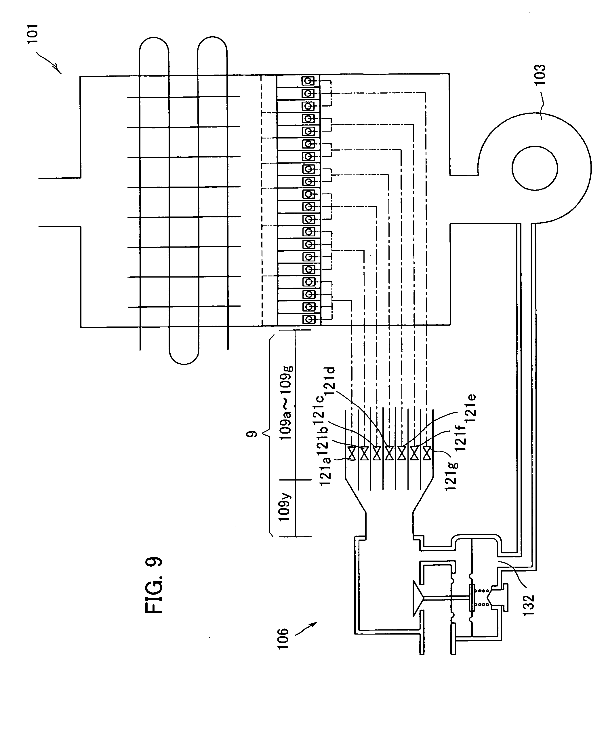
[0016] The present inventor experimentally produced a combustion apparatus 101, as shown in FIG. 9, having a pressure equalizing valve 106 disposed at a fuel gas supply channel so that a pressure signal for the pressure equalizing valve 106 is taken out from an air feeder 103.
[0017] Herein, the pressure equalizing valve 106 is a pressure regulator for reducing a primary pressure of supplied gas to a secondary pressure and for discharging the regulated gas, having a signal pressure inlet 132 through which a pressure is introduced as a signal, so as to discharge the gas with a pressure reduced to the secondary pressure in accordance with a pressure introduced through the signal pressure inlet 132.
[0018] In the combustion apparatus 101 experimentally produced by the present inventor, because the pressure signal is taken out from the air feeder 103, a supply pressure of fuel gas is changed in accordance with either increase or decrease of the air feeding amount by the air feeder 103. That solves the above-mentioned technical problem such as an unstable combustion in the transition in changing of the combustion amount. Further, the experimentally produced combustion apparatus 101 changes the combustion amount by changing of the air feeding amount by the air feeder 3, thereby eliminating the fuel-gas proportional valve.
[0019] However, the combustion apparatus 101 includes a plurality of branched channels 109a to 109g in a fuel supply channel 109 with shutoff valves 121a to 121g, respectively. Changing of the fuel amount by either opening or closing of the shutoff valves 121a to 121g may cause an unstable combustion.
[0020] The reason is as follows: The pressure equalizing valve or the pressure regulator 106 employed in the combustion apparatus 101 is designed to regulate a secondary pressure of fuel gas so as to substantially conform a pressure introduced through the signal pressure inlet 132 to a discharge pressure of the fuel gas discharged from the pressure regulator 106. When some of the shutoff valves 121a to 121g are closed, for example, a flow amount of fuel gas flowing in a common flow channel 109y of the fuel supply channel 109 is reduced and a flow rate of the gas in the fuel supply channel 109 is lowered, compared to those before closing of the valves 121. Herein, in view that a pipe resistance of fuel gas is proportional to the square of the flow rate of fuel gas according to Bernoulli's principle, a flow resistance of the common flow channel 109y is lowered. As a consequence, when some of the shutoff valves 121a to 121g are closed, the secondary pressure of the fuel gas flowing in the remaining branched channels 109a to 109g having the opened shutoff valves 121 is increased. That may change the air-fuel ratio of the gas mixture, resulting in an unstable combustion. Shortly, the fuel gas may become thick and combustion may become unstable.
[0021] As described above, water heaters for household use each require an amount and a temperature of hot water changing greatly. Therefore, a combustion apparatus must change a combustion amount depending on a condition such as the amount of hot water. However, the experimentally produced combustion apparatus 101 may cause an unstable combustion each time the combustion amount is changed by using the shutoff valves 121a to 121g.
[0022] An object of the present invention made in view of the problems and drawbacks in the conventional art described above is therefore to further improve the experimentally produced combustion apparatus and develop a combustion apparatus solving the technical problem in which changing of the combustion amount by using the shutoff valves 121 causes an unstable combustion.
Means to Solve the Problem
[0023] Generally, a pressure regulator is designed to regulate a discharge pressure from the pressure regulator to be in conformity with a signal pressure. The pressure regulator generally has a portion where the discharge pressure is detected within the regulator. In contrast, a pressure regulator employed in a combustion apparatus in the present invention is designed to introduce a signal for a secondary pressure (discharge-side) from outside of the pressure regulator.
[0024] Specifically, in order to solve the problems and drawbacks described above, an aspect of the present invention provided herein is a combustion apparatus including a plurality of burners, a fuel supply channel having a plurality of branched channels at its downstream, an air feeder for supplying air to the burners, and a pressure regulator, and having a combustion space containing a combusting area, the branched channels allowing supplied fuel to the burners to pass therethrough, at least one of the branched channels having a shutoff valve, which is either opened or closed so as to either increase or decrease the combusting area in the combustion space, and the pressure regulator having a signal-pressure inlet through which a signal pressure to be based on is introduced and a secondary-pressure inlet through which a secondary pressure is introduced and being designed to regulate fuel gas supplied at a primary pressure to gas having a discharge pressure satisfying a predetermined relationship between the signal pressure introduced through the signal-pressure inlet and the secondary pressure introduced through the secondary-pressure inlet, wherein the signal pressure introduced through the signal-pressure inlet is detected at a position selected from the air feeder and a downstream of the air feeder, and the secondary pressure introduced through the secondary-pressure inlet is detected at a position selected from the branched channels and a vicinity of a boundary of the branched channels within the fuel supply channel.
[0025] The combustion apparatus in this aspect employs the pressure regulator including the signal-pressure inlet through which a signal pressure detected at the air feeder or the downstream of the air feeder is introduced and the secondary-pressure inlet through which a secondary pressure detected at the fuel supply channel is introduced.
[0026] As described above, the experimentally produced combustion apparatus is designed to regulate a secondary pressure of fuel gas so that a pressure introduced through the signal-pressure inlet becomes substantially equal to a discharge pressure of the fuel gas to be discharged from the pressure regulator. That disadvantageously causes an unstable combustion resulting from a change of the air-fuel ratio of the gas mixture of air and fuel gas when, for example, some of the shutoff valves disposed at the branched channels are closed.
[0027] Therefore, the combustion apparatus in this aspect is provided with the secondary-pressure inlet, so as to regulate a discharge pressure from the pressure regulator satisfying a predetermined relationship between the signal pressure introduced through the signal-pressure inlet and the secondary pressure in the fuel supply channel, which is detected at the vicinity of the boundary upstream of the branched channels in the fuel supply channel. Thereby, the secondary pressure in the fuel supply channel is maintained constantly because being regulated in accordance with the basic signal pressure even when some of the shutoff valves disposed at the branched channels are closed. Consequently, by the combustion apparatus in this aspect, even when the combusting area is either increased or decreased by a control of either opening or closing of the shutoff valves, the air-fuel ratio of the gas mixture of fuel gas and air undergoes very little change though the amount of fuel gas undergoes a change by the control, thereby preventing an unstable combustion, because of a direct control of the secondary pressure in the vicinity of the boundary upstream of the branched channels in the fuel supply channel adjacent to the burners.
[0028] Preferably, the fuel supply channel has a secondary-pressure outlet through which the secondary pressure to be introduced into the pressure regulator is taken out, the secondary-pressure outlet being disposed at upstream of the shutoff valves in the branched channels.
[0029] By such the combustion apparatus, the secondary-pressure outlet is disposed at the branched channels, so that the secondary pressure at a position closer to the burners is regulated in accordance with the basic signal pressure. That minimizes the influence such as a pipe resistance onto the fuel gas supplied to the burners, thereby ensuring a constant air-fuel ratio. Further, even when the combusting area is decreased by closing of the shutoff valves, the detected secondary pressure undergoes very little change because the secondary-pressure outlet is disposed at upstream of the shutoff valves in the branched channels. Therefore, the air-fuel ratio is substantially accurately regulated.
[0030] The secondary-pressure outlet is preferably disposed at one of the branched channels where a flow of fuel gas is protected from being blocked even with either increase or decrease of the combusting area in the combustion operation.
[0031] By such a configuration, the secondary pressure is detected at one of the branched channels through which fuel gas usually flows, and whereby the air-fuel ratio is more accurately regulated even with closing of the shutoff valves.
[0032] Preferably, the combustion apparatus has a plurality of secondary-pressure outlets through which the secondary pressure to be introduced into the pressure regulator is taken out and is designed to change positions where the secondary pressure is detected.
[0033] It is also recommended that the combustion apparatus has a pressure modification means for modifying a pressure to be detected, the pressure modification means being disposed adjacent to the position where either the signal pressure or the secondary pressure in accordance with the signal pressure is detected and being controlled so as to modify the detected pressure.
[0034] Such the combustion apparatus allows the ratio of fuel gas to be modified compared to the air-fuel ratio in the normal combustion, as needed.
[0035] By this combustion apparatus, for example, in a case where the pressure modification means is disposed adjacent to the position where the signal pressure is detected, the pressure modification means is controlled to direct an air flow to the detecting position, thereby making a dynamic pressure of the fed air to act on the detecting position. That raises the signal pressure without increasing the number of rotations of the air feeder, enabling a control to increase the ratio of fuel gas than the air-fuel ratio in the normal combustion. Alternatively, the pressure modification means is controlled to block an air flow to the detecting position, thereby blocking a dynamic pressure of the fed air from acing on the detecting position. That allows the signal pressure (static pressure) in accordance with the original number of rotations of the air feeder to be introduced into the pressure regulator, enabling combustion at the air-fuel ratio in the normal combustion. Further, by application of the characteristic features of the pressure modification means, only with a control of the pressure modification means to slightly direct an air flow to the detecting position (viz. control to make a dynamic pressure to slightly act) in the normal combustion, more dynamic pressure can act on the detecting position by the control of the means to direct more air to the detecting position in order to raise the signal pressure than that in the normal combustion, whereas the dynamic pressure is blocked from acting on the detecting position and the static pressure can act thereon by the control of the means to block an air flow to the detecting position in order to reduce the signal pressure than that in the normal combustion. That enables the control to modify the air-fuel ratio that is constantly regulated by the pressure regulator, as needed.
[0036] On the other hand, in a case where the pressure modification means is disposed adjacent to the position where the secondary pressure is detected, the pressure modification means is controlled to direct a flow of fuel gas to the detecting position, thereby making a dynamic pressure to act on the detecting position. A pressure larger than the original secondary pressure (static pressure) of fuel gas actually flowing in the flow channel is detected, so as to be regulated to become equal to the signal pressure. That makes fuel gas supplied to the combustion space to have a smaller ratio than the air-fuel ratio in the normal combustion. Alternatively, the pressure modification means is controlled to block a flow of fuel gas to the detecting position, thereby blocking a dynamic pressure from acing on the detecting position and making a static pressure to act thereon. That allows fuel gas having the original secondary pressure in accordance with the signal pressure to be introduced into the pressure regulator. Thus, the fuel gas has a ratio equal to the air-fuel ratio in the normal combustion. Consequently, as well as in the above-mentioned description, by application of the characteristic features of the pressure modification means, only with a control of the pressure modification means to make a dynamic pressure to slightly act on a flow of fuel gas in the normal combustion, the means can be controlled to direct more fuel gas to the detecting position in order to reduce the ratio of fuel gas than the air-fuel ratio in the normal combustion, whereas the means can be controlled to block a flow of fuel gas to the detecting position in order to increase the ratio of fuel gas than the air-fuel ratio in the normal combustion. That also enables the control to modify the air-fuel ratio that is constantly regulated by the pressure regulator, as needed.
[0037] Consequently, by this combustion apparatus, the control of the pressure modification means arranged adjacent to the detecting position of either of the pressures regulates fuel gas with a ratio shifted from the air-fuel ratio in the normal combustion, as needed. That improves ignition performance in ignition and reduces an unstable combustion such as an oscillating combustion within a certain period of time after ignition.
[0038] The pressure modification means is preferably controlled so as to increase the detected pressure in ignition in the combustion space.
[0039] Such a configuration increases a ratio of fuel gas in ignition than the air-fuel ratio in the normal combustion, thereby ensuring an improved ignition performance. Herein, the term "in ignition" includes timing before and after generation of flames in the combustion space.
[0040] Preferably, the pressure regulator has inside a main valve and a main-valve drive mechanism for driving the main valve, the main-valve drive mechanism being designed to drive the main valve with a gas composed of one selected from fuel gas and air from the air feeder, and including a chamber into which the gas is introduced, a gas supply part for supplying the gas to the chamber, and a leak channel for leaking the gas within the chamber, wherein the gas supply part is temporally closed in decreasing the combusting area in the combustion space.
[0041] The pressure regulator may be either a direct acting type or a pilot type. The gas (working fluid) may be either air from the air feeder or fuel gas.
[0042] This configuration solves the technical problem such as an unstable combustion even when the combusting area is changed with the shutoff valves and the like.
ADVANTAGEOUS EFFECT OF THE INVENTION
[0043] The present invention can provide a combustion apparatus to solve the technical problem such as an unstable combustion even when the combustion amount is changed with the shutoff valves and the like.
BRIEF DESCRIPTION OF THE DRAWINGS
[0044] FIG. 1 is a configuration diagram showing a combustion apparatus relating to an embodiment of the present invention;
[0045] FIG. 2 is a configuration diagram showing a modified embodiment of the combustion apparatus of the present invention;
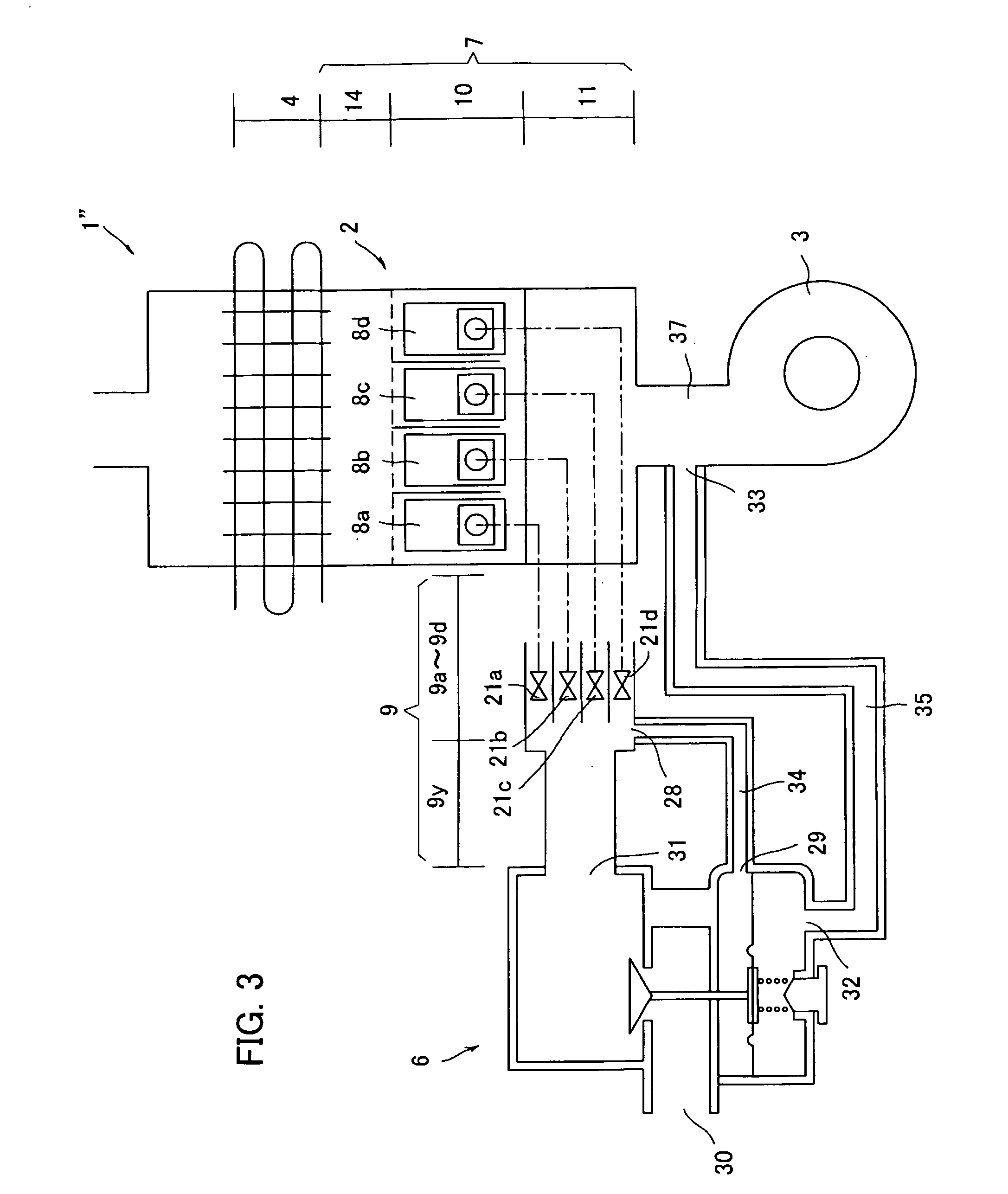
[0046] FIG. 3 is a configuration diagram showing another modified embodiment of the combustion apparatus of the present invention;
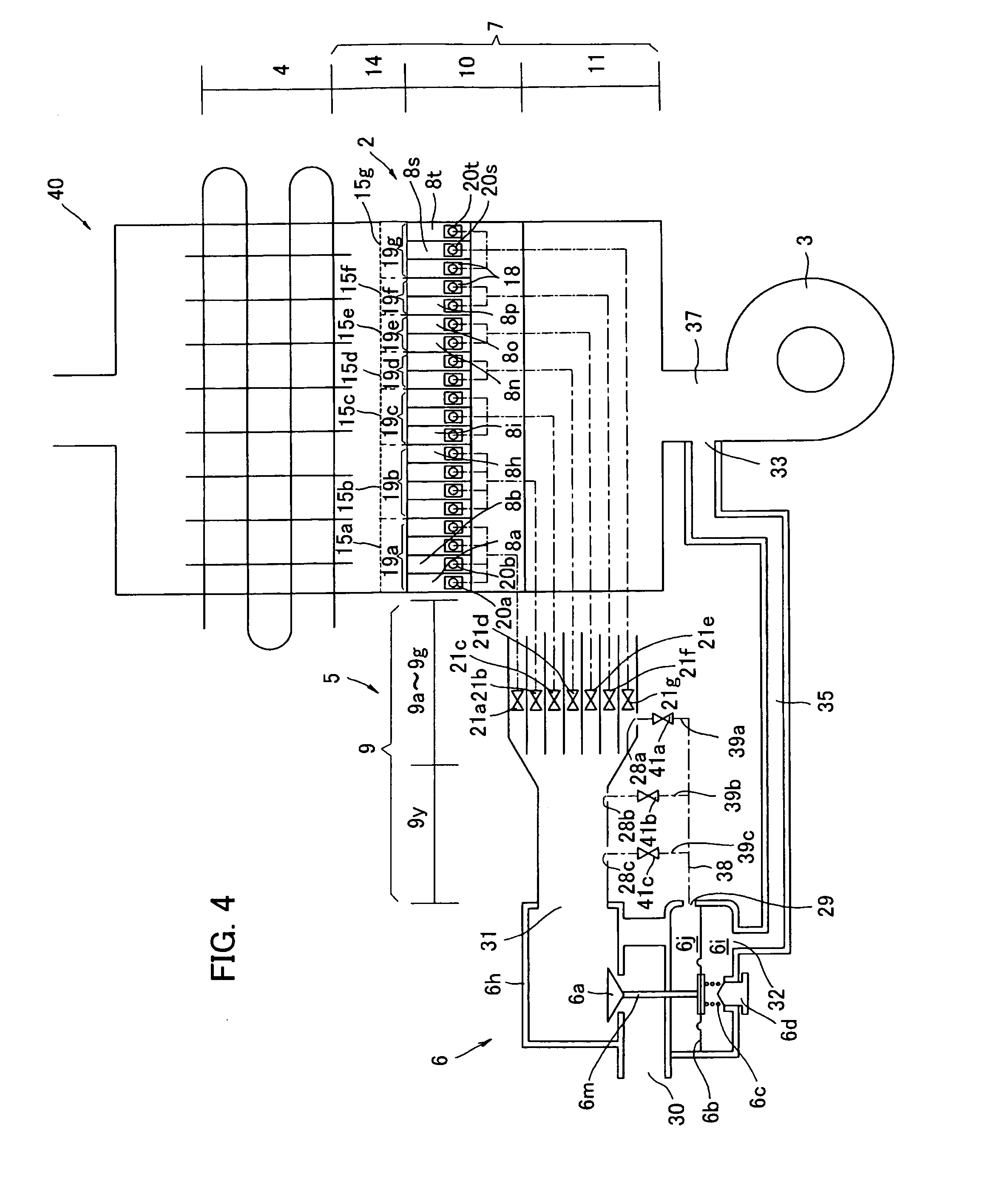
[0047] FIG. 4 is a configuration diagram showing still another modified embodiment of the combustion apparatus of the present invention;
[0048] FIG. 5 is a configuration diagram showing yet another modified embodiment of the combustion apparatus of the present invention;
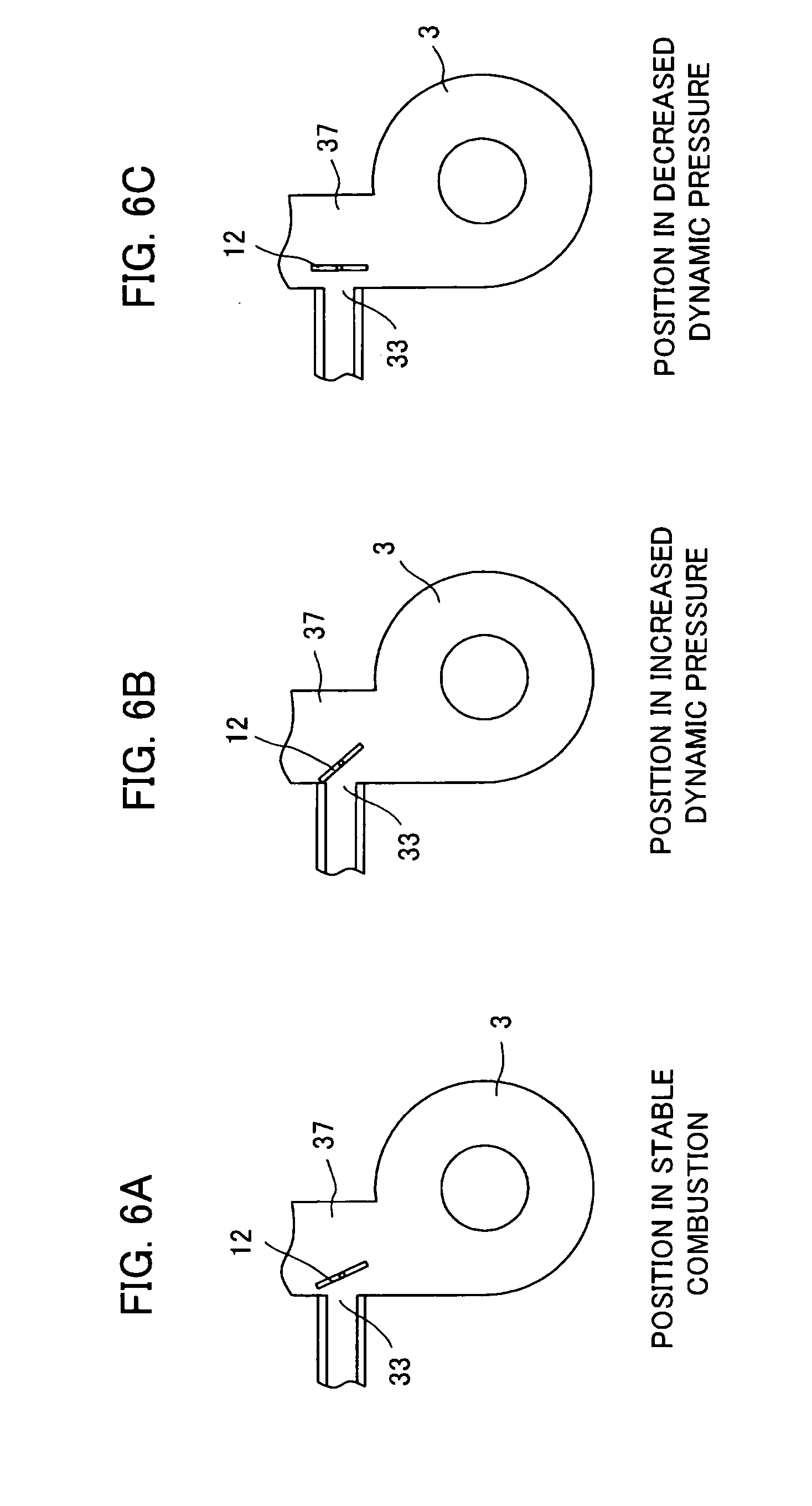
[0049] FIGS. 6A to 6C are conceptual diagrams each showing a control state of a pressure modification board. FIG. 6A shows a state at a position in a stable combustion, FIG. 6B shows a state at a position in an increased dynamic pressure, and FIG. 6C shows a state at a position in a decreased dynamic pressure;
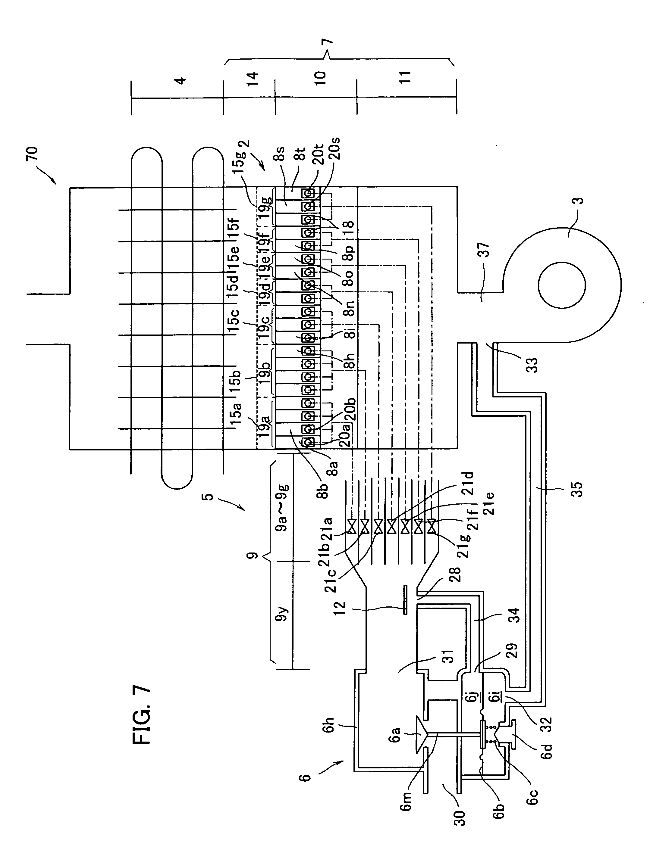
[0050] FIG. 7 is a configuration diagram showing a further modified embodiment of the combustion apparatus of the present invention;
[0051] FIG. 8 is a configuration diagram showing a further modified embodiment of the combustion apparatus of the present invention; and
[0052] FIG. 9 is a configuration diagram showing a combustion apparatus experimentally produced by the present inventor.
DESCRIPTION OF THE PREFERRED EMBODIMENT
[0053] Now, an embodiment of the present invention will be described below in detail, making reference to the accompanying drawings. Hereafter, a positional relationship of the left, right, top, and bottom is described on a basis of the drawings unless otherwise noted.
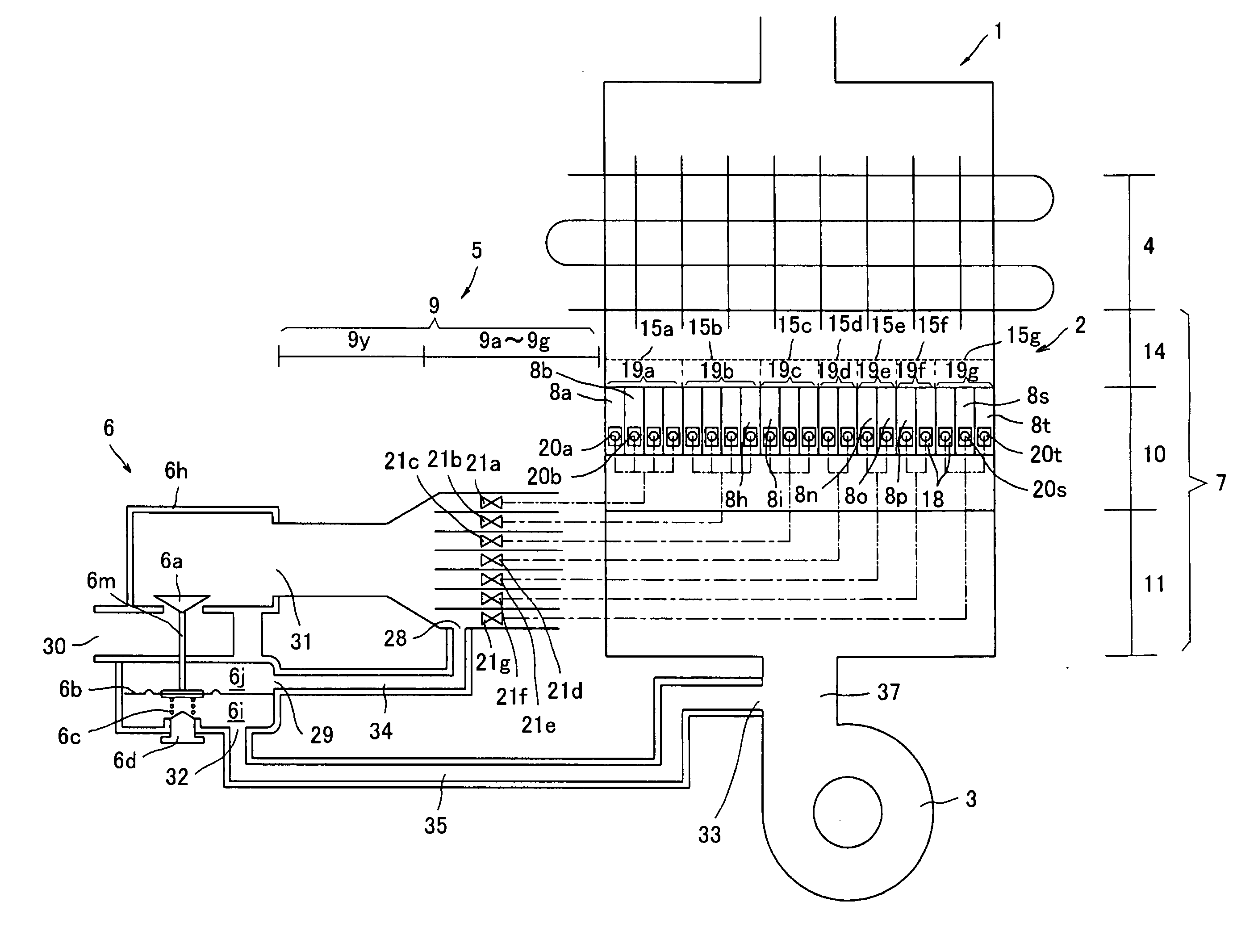
[0054] A combustion apparatus 1 shown in FIG. 1 is housed in a water heater not shown so as to heat a heat exchanger 4 and the like and mainly consists of a main body 2, an air feeder 3, a forming unit 5 for forming a fuel supply channel, and a pressure regulator (hereinafter also referred to as a pressure equalizing valve) 6.
[0055] The air feeder 3 employed in the present embodiment is constituted by a moving vane housed rotatably in a casing, like a sirocco fan and a turbo fan. A motor for driving the air feeder 3 is either a DC motor or an inverter-controlled AC motor, changing an air feeding amount by either increase or decrease of the number of rotations.
[0056] The main body 2 includes twenty (20) burners 8a to 8t housed in a burner casing 7, in which the burners 8a to 8t consist of seven burner groups 19a to 19g. More specifically, as shown in FIG. 1, a first group 19a consists of four burners 8a to 8d, a second group 19b consists of four burners 8e to 8h, a third group 19c consists of three burners 8i to 8k, a fourth group 19d consists of two burners 8l to 8m, a fifth group 19e consists of two burners 8n to 8o, a sixth group 19f consists of two burners 8p to 8q, and a seventh group 19g consists of three burners 8r to 8t. Herein, all the burners 8a to 8t employed in the present embodiment have the same configuration and the same capacity.
[0057] The burner casing 7 is, as shown in FIG. 1, divided into two tiers by a partition. A part downstream in an air flowing direction functions as a burner mounting part 10, whereas another part upstream in the air flowing direction functions as an air-passage forming part 11. The air-passage forming part 11 functions as a passage through which air is introduced into the burners 8a to 8t and forms a portion of an air supply passage 37. Flames are to be generated at an upper part of the burner mounting part 10, that is: the upper part of the burner mounting part 10 functions as a combustion space 14.
[0058] The burner mounting part 10 defines seven chambers. The burners 8a to 8t are sorted into the numbers set with respect to each chamber as described above and inserted into the respective chambers.
[0059] Each of the burners 8a to 8t has an air-gas inlet 18 at its end and burner ports not shown at its top face. The burner ports are disposed at the most downstream in a gas-mixture flowing direction in the burners 8a to 8t, so as to generate flames in the combustion space 14.
[0060] In the present embodiment, there are respectively provided nozzles 20a to 20t adjacent to the air-gas inlets 18 of the burners 8a to 8t, so that fuel gas is introduced into the burners 8a to 8t through the respective nozzles 20a to 20t. Further, the air-passage forming part 11 is communicated with ends of the burners 8a to 8t, so that air is introduced into the burners 8a to 8b through the air-gas inlets 18 from the air-passage forming part 11.
[0061] Air and fuel gas are introduced through the air-gas inlets 18 and mixed passing in the burners 8a to 8t and the resulting gas mixture is discharged from the burner ports.
[0062] The fuel-supply-channel forming unit 5 includes a fuel supply channel 9 for supplying fuel gas to the burners 8a to 8t through the respective nozzles 20a to 20t.
[0063] The fuel supply channel 9 consists of seven branched channels 9a to 9g at downstream in the fuel-gas flowing direction and a common channel 9y through which fuel gas flows to all the branched channels 9a to 9g at upstream in the fuel-gas flowing direction.
[0064] The combustion space 14 has a plurality of combustion areas defined by the groups 19a to 19g. Specifically, the combustion areas are divided into the number of the groups 19a to 19g, and more specifically into seven divided areas 15a to 15g.
[0065] Therefore, the combustion apparatus 1 in the present embodiment generates uniform flames in the respective burners 8a to 8t and allows uniform combustion in the respective areas 15a to 15g.
[0066] The forming unit 5 is provided with conventional art shutoff valves (electromagnetic valves) 21a to 21g in the branched channels 9a to 9g respectively.
[0067] Next, the pressure regulator 6 employed in this embodiment will be described in detail below.
[0068] The pressure regulator 6 is specifically a pressure equalizing valve, a kind of a pressure reducing valve, and is designed to reduce a primary pressure of supplied fuel gas to a secondary pressure, so as to discharge the resulting gas with a reduced pressure. An ordinary pressure reducing valve is designed to regulate a secondary pressure to a predetermined pressure, whereas the pressure equalizing valve employed in this embodiment is characteristically designed to change a discharge pressure in accordance with a signal pressure.
[0069] Specifically, the pressure regulator 6 mainly consists of a gas inlet 30, a gas outlet 31, a signal-pressure inlet 32 through which a pressure is introduced as a signal, and a secondary-pressure inlet 29 through which a secondary pressure in the fuel supply channel 9 is introduced. The pressure regulator 6 is designed to reduce a primary pressure of fuel gas introduced from the gas inlet 30 to a secondary pressure and discharge the resulting gas from the gas outlet 31. The pressure regulator 6 is designed to reduce the pressure of fuel gas so as to satisfy a predetermined relationship between a signal pressure (also referred to as a basic signal pressure) introduced through the signal-pressure inlet 32 and a secondary pressure introduced through the secondary-pressure inlet 29.
[0070] The pressure regulator 6 is defined by an outer frame 6h forming a gas passage and incorporates a valve body 6a for controlling an opening degree of the gas passage, a diaphragm 6b, a spring 6c, and a controlling mechanism 6d.
[0071] Within the outer frame 6h, the diaphragm 6b defines a signal pressure chamber 6i, in which the signal-pressure inlet 32 is formed. The signal-pressure inlet 32 is connected to the air feeder 3 via a signal-pressure conducting pipe 35. Therefore, the signal pressure chamber 6i is subjected to a signal pressure introduced through the signal-pressure inlet 32. That applies the signal pressure upon one side facing the signal pressure chamber 6i of the diaphragm 6b.
[0072] Meanwhile, the diaphragm 6b also defines a secondary pressure chamber 6j at a side opposed to the signal pressure chamber 6i (the other side), in the chamber 6j the secondary-pressure inlet 29 is formed. The secondary pressure chamber 6j is communicated with the fuel supply channel 9 (a secondary-pressure side) via a secondary-pressure conducting pipe 34. Thus, the diaphragm 6b is subjected to a pressure difference between a signal pressure Pt and a secondary pressure P2 of the fuel supply channel 9. In this embodiment, the diaphragm 6b is subjected to a pressure difference between the signal pressure Pt and the secondary pressure P2 of the branched channel 9g.
[0073] The spring 6c supports the diaphragm 6b and strength of the spring 6c is controlled by the controlling mechanism 6d.
[0074] The valve body 6a is, as described above, designed to control the opening degree of the gas passage and connected to the diaphragm 6b via a stem 6m.
[0075] By the pressure regulator 6 employed in this embodiment, when a primary pressure P1 of fuel gas introduced into the pressure regulator 6 is increased, for example, the secondary pressure (pressure in the branched channel 9g) P2 is increased in accordance with the pressure change of the primary pressure P1. The pressure change of the secondary pressure P2 makes the valve body 6a to move downwardly. Specifically, a pressure balance between the secondary pressure P2 introduced through the secondary-pressure inlet 29 and the signal pressure Pt acting on the opposite side across the diaphragm 6b is temporally lost. The secondary pressure P2 becomes larger than the signal pressure Pt and the increased secondary pressure P2 induces the diaphragm 6b to expand downwardly. That moves the valve body 6a downwardly, whereby an area in which fuel gas passes is narrowed. The secondary pressure P2 of the fuel gas having passed in the narrowed area is reduced and thus regulated so as to become substantially equal to the signal pressure Pt again.
[0076] When the signal pressure Pt is increased, for example, the valve body 6a moves upwardly in accordance with the pressure change of the signal pressure Pt so as to increase the secondary pressure P2, thereby regulating the secondary pressure P2 to become substantially equal to the signal pressure Pt. Specifically, a pressure balance between the secondary pressure P2 introduced through the secondary-pressure inlet 29 and the signal pressure Pt acting on the opposite side across the diaphragm 6b is temporally lost. The signal pressure Pt becomes larger than the secondary pressure P2 and the increased signal pressure Pt induces the diaphragm 6b to expand upwardly. That moves the valve body 6a upwardly, whereby the area in which fuel gas passes is widened. The secondary pressure P2 of the fuel gas having passed in the widened area is increased and thus regulated so as to become substantially equal to the signal pressure Pt again. In this way, the secondary pressure P2 in the branched channel 9g is regulated so as to be substantially equal to the signal pressure Pt even when the primary pressure P1 or the signal pressure Pt changes.
[0077] The pressure regulator 6 is connected to a fuel gas supply source not shown via the gas inlet 30 and to one end (upstream end in the fuel-gas flowing direction) of the forming unit 5 near the common channel 9y via the gas outlet 31. The branched channels 9a to 9g are connected to the other end (downstream end in the fuel-gas flowing direction) of the common channel 9y.
[0078] The branched channel 9g is provided with a secondary-pressure outlet 28 above the shutoff valve 21g in the fuel-gas flowing direction. The secondary-pressure outlet 28 is connected to the secondary-pressure inlet 29 of the pressure regulator 6 via the secondary-pressure conducting pipe 34. This embodiment has a configuration in which the secondary-pressure inlet 29 and the secondary-pressure outlet 28 are integrated with the secondary-pressure conducting pipe 34, but it is possible to have a configuration in which the conducting pipe 34 is connected to the inlet 29 and the outlet 28 by a fixing means such as a bolt and a nut not shown. This configuration is attachable to an existing combustion apparatus, thereby reducing a manufacturing cost.
[0079] The signal pressure of the pressure regulator 6 is detected at an outlet of the air feeder 3. Specifically, as shown in FIG. 1, the signal pressure is detected at a middle portion between the air feeder 3 and the burner casing 7. Therefore, there is provided a signal-pressure outlet 33 in the middle portion (air supply passage 37) between the air feeder 3 and the burner casing 7. The signal-pressure outlet 33 and the signal-pressure inlet 32 are connected by the signal-pressure conducting pipe 35.
[0080] The above-mentioned embodiment illustrates the pressure equalizing valve 6 of a direct acting type, but the present invention may employ a pressure equalizing valve of a pilot type not shown.
[0081] Next, a function of the combustion apparatus 1 will be described in detail below.
[0082] In the combustion apparatus 1 in the present embodiment, the air feeder 3 is driven and the shutoff valves 21a to 21g are opened, so as to introduce fuel and air into the burners 8a to 8t, in which the fuel and the air are mixed to produce a fuel-air gas mixture. The resulting gas mixture is discharged from the burner ports not shown of the burners 8a to 8t so as to generate flames within the combustion space 14.
[0083] More specifically, the air feeder 3 is driven to feed air into the burner casing 7. The air having been fed from the air feeder 3 is once introduced into the air-passage forming part 11 in the burner casing 7, then flowing through the part 11 to the ends of the burners 8a to 8t, and finally being supplied to each of the burners 8a to 8t through the air-gas inlets 18.
[0084] The amount of air to be introduced into each of the burners 8a to 8t varies as a function of an air pressure in the vicinity of the respective air-gas inlet 18 of each of the burners 8a to 8t, an opening area of the air-gas inlet 18, an internal resistance of each of the burners 8a to 8t, a resistance (exhaust air resistance) at downstream of each of the burners 8a to 8t in the air flowing direction, and an atmospheric pressure.
[0085] The opening area of the air-gas inlet 18 remains unchanged during combustion. The internal resistance in each of the burners 8a to 8t is also constant. Further, it is taken for granted that the resistance at downstream of each of the burners 8a to 8t (exhaust air resistances) and the atmospheric pressure are substantially constant.
[0086] Thus, variations of the amount of air to be introduced into each of the burners 8a to 8t correlates most strongly with changes in air feeding pressure in the vicinity of the respective air-gas inlet 18. That is, it is practically convenient to regard that the amount of air to be introduced into each of the burners 8a to 8t is varied only by changes in pressure in the vicinity of the air-gas inlet 18.
[0087] Further, it may be said that the pressure in the vicinity of the air-gas inlet 18 is determined by a discharge pressure of the air feeder 3, ignoring a condition such as pressure loss in the burners 8a to 8t.
[0088] On the other hand, the fuel gas is introduced from the fuel gas supply source into the pressure regulator 6, which reduces the pressure of the fuel gas. The regulated fuel gas having flowed out of the pressure regulator 6 enters the fuel supply channel 9 of the fuel-supply-channel forming unit 5, flows through the branched channels 9a to 9g, and is discharged through the nozzles 20a to 20t. The nozzles 20a to 20t are disposed at positions opposite the air-gas inlets 18 of the respective burners 8a to 8t. The fuel gas having been discharged from each nozzle 20a to 20t enters each of the burners 8a to 8b through the air-gas inlet 18, so as to be mixed with air and to be discharged from the respective burner ports not shown. Flames are generated in the combustion space 14.
[0089] The amount of fuel gas to be introduced into each of the burners 8a to 8t is equal to the amount of fuel gas flowing through each of the branched channels 9a to 9g.
[0090] The amount of fuel gas flowing through each of the branched channels 9a to 9g varies as a function of a gas pressure at upstream of each of the branched channels 9a to 9g in the fuel-gas flowing direction, an opening area of each of the branched channels 9a to 9g, an internal resistance of each of the branched channels 9a to 9g, an opening diameter of each of the nozzles 20a to 20t, and an atmospheric pressure at an outlet of each of the nozzles 20a to 20t.
[0091] The opening area and the internal resistance of each of the branched channels 9a to 9g and the opening diameter of each of the nozzles 20a to 20t remain unchanged during combustion. Further, the atmospheric pressure at the outlet of each of the nozzles 20a to 20t is substantially constant.
[0092] Thus, variations of the amount of fuel gas to be introduced into each of the burners 8a to 8t correlates most strongly with changes in pressure of fuel gas at upstream of each of the branched channels 9a to 9g. That is, it is practically convenient to regard that the amount of fuel gas to be introduced into each of the burners 8a to 8t is determined only by changes in gas pressure at upstream of each of the branched channels 9a to 9g.
[0093] The combustion apparatus 1 in this embodiment detects a signal pressure of the pressure regulator 6 at the vicinity of the outlet of the air feeder 3, so as to change a secondary pressure of the branched channel 9g connected to the pressure regulator 6 in accordance with the detected signal pressure.
[0094] Therefore, the amounts of air and fuel gas to be introduced into the respective burners 8a to 8t are changed by the discharge pressure of the air feeder 3, which is substantially equal to the signal pressure of the signal-pressure outlet 33. Increasing of the amount of air introduced into the burners 8a to 8t by raising of the discharge pressure of the air feeder 3 raises the discharge pressure of fuel gas from the pressure regulator 6 in accordance with raising of the signal pressure of the pressure regulator 6, thereby increasing the amount of the fuel gas flowing in the fuel supply channel 9, so that the amount of the fuel gas introduced into the burners 8a to 8t is increased. Consequently, in this embodiment, a ratio between the amounts of air and fuel gas to be introduced into each of the burners 8a to 8t is constant at all times. Shortly, air and fuel gas are introduced into each of the burners 8a to 8t at an appropriate ratio between those.
[0095] Further, in the combustion apparatus 1 in the present invention, closing of some of the shutoff valves (electromagnetic valves) 21a to 21g disposed in the respective branched channels 9a to 9g can change the combustion amount. By the combustion apparatus 1 in this embodiment, such a case also achieves the similar effect as described above.
[0096] Closing of the five shutoff valves 21a to 21e among the seven valves 21a to 21g shown in FIG. 1, for example, stops supply of fuel gas to the burners 8a to 8o in the groups 19a to 19e, so that the burners 8p to 8t in the groups 19f and 19g generate combustion in the combustion space 14. Even in the above-mentioned case, the ratio between the amounts of air and fuel gas introduced into the burners 8a to 8h remains unchanged due to the pressure regulator 6.
[0097] That means, because air is continuously introduced into all the burners 8a to 8t even when the shutoff valves 21a to 21e are closed, a total amount of air discharged outside through the burners 8a to 8t remains unchanged. That allows no change in the discharge pressure of the air feeder 3. Consequently, the signal pressure of the pressure regulator 6 remains unchanged.
[0098] Further, because the pressure regulator 6 has the secondary-pressure inlet 29 and is communicated with the secondary-pressure outlet 28 of the branched channel 9g via the secondary-pressure conducting pipe 34 as described above, the secondary pressure in the vicinity of the branched channel 9g is regulated to be constant in accordance with the signal pressure. In other words, even when some of the shutoff valves 21a to 21g are closed, the pressure regulator 6 modifies the pressure of fuel gas to be discharged so as to constantly maintain the secondary pressure in the vicinity of the branched channel 9g. Further, the secondary-pressure outlet 28 is near to the burners 8a to 8t because being disposed in the branched channel 9g. That allows a small influence by pressure loss, making the air-fuel ratio in the burners 8a to 8t less likely to change.
[0099] Specifically, even when the shutoff valves 21a to 21e are closed to stop fuel gas flowing to the closed branched channels 9a to 9e, the pressures of fuel gas flowing in the branched channels 9f and 9g, in which the respective shutoff valves 21f and 21g are opened, are regulated to be constant in accordance with the signal pressure, thus remaining unchanged. Consequently, regardless of the control of either opening or closing of the shutoff valves 21a to 21e, the same amount of fuel gas flows in the branched channels 9f and 9g, in which the respective shutoff valves 21f and 21g are opened. Herein, it is preferable to usually open the shutoff valve 21g of the branched channel 9g provided with the secondary-pressure outlet 28 in either increasing or decreasing the combustion amount during combustion.
[0100] The above-mentioned example illustrates the case in which five of the shutoff valves among the seven valves 21a to 21g are closed, but the similar effect is achieved and the ratio of the amounts of air and fuel gas supplied to the burners to be used for combustion remains unchanged even when less than or more than five of the valves are closed. That avoids an unstable combustion even when the shutoff valves 21a to 21g are used to control the combustion amount.
[0101] The above-mentioned embodiment illustrates a configuration in which the secondary-pressure outlet 28 is disposed in the branched channel 9g of the fuel supply channel 9, but the present invention is not limited thereto and may have a configuration in which the outlet 28 is disposed in any of the branched channels 9a to 9f, for example. In this case, it is preferable to dispose in one of those where a flow of fuel gas is not obstructed during combustion. In other words, it is preferable to select one having the shutoff valve never closed during combustion. By this configuration, an accurate air-fuel ratio is maintained even when any of the shutoff valves 21a to 21g is closed.
[0102] Further, the above-mentioned embodiment illustrates a configuration in which the shutoff valves 21a to 21g is provided at all the branched channels 9a to 9g respectively and the secondary-pressure outlet 28 is disposed in the branched channel 9g provided with the shutoff valve 21g, but the present invention is not limited thereto and may have a configuration in which shutoff valves are provided in some of the branched channels 9a to 9g and a secondary-pressure outlet is disposed in one of branched channels without the shutoff valve. The similar effect as the above-mentioned embodiment is also achieved by this configuration.
[0103] Further, the above-mentioned embodiment has a configuration in which the secondary-pressure outlet 28 is disposed in one of the branched channels 9a to 9g, but the present invention is not limited thereto and may have a configuration, as in a combustion apparatus 1' shown in FIG. 2, in which the outlet 28 is disposed in the common channel 9y. In this case, it is preferable to dispose at downstream (in the fuel-gas flowing direction) of the common channel 9y and adjacent to the boundary with the branched channels 9a to 9g. That regulates a pressure adjacent to the boundary between the common channel 9y and the branched channels 9a to 9g to a pressure equal to the signal pressure. Therefore, the similar effect as the above-mentioned embodiment is achieved.
[0104] Further, the above-mentioned embodiment has a configuration in which one branched channel is arranged in each of the seven groups 19a to 19g each consisting of the different number of burners 8a to 8t, but the present invention is not limited thereto and may have a configuration, as in a combustion apparatus 1'' shown in FIG. 3, in which the number of burners 8a to 8d is equal to that of the branched channels 9a to 9d, for example.
[0105] Further, the above-mentioned embodiment has a configuration in which only one secondary-pressure outlet 28 is provided in the fuel supply channel 9, but the present invention is not limited thereto and may have a configuration in which a plurality of secondary-pressure outlets 28 are provided in the fuel supply channel 9. As in a combustion apparatus 40 shown in FIG. 4, for example, secondary-pressure outlets 28a to 28c are respectively arranged in the branched channel 9g, a downstream portion of the common channel 9y, and a middle portion of the common channel 9y. Further, the pressure regulator 6 is connected to a secondary-pressure conducting pipe 38 via the secondary-pressure inlet 29. The pipe 38 has three branch pipes 39a to 39c, an end of each pipes 39a to 39c being communicated with one of the outlets 28a to 28c. In this embodiment, the outlet 28a is communicated with the pipe 39a, the outlet 28b is communicated with the pipe 39b, and the outlet 28c is communicated with the pipe 39c. The branch pipes 39a to 39c are respectively provided with shutoff valves (electromagnetic valves) 41a to 41c. This configuration allows a more practical control than the combustion apparatus 1 in the above-mentioned embodiment.
[0106] In the fuel supply channel 9, fuel gas is subjected to pressure loss because of a pipe resistance, having a pressure reduced toward downstream. Specifically, in a stable combustion (in the normal combustion) after the elapse of a certain period of time after ignition, an actual pressure is decreasing toward downstream in this way: pressure at the branch pipe 39c>pressure at the branch pipe 39b>pressure at the branch pipe 39a.
[0107] Thus, a configuration in which the secondary pressure can be detected at various positions and the positions can be changed helps slight change in pressure of fuel gas discharged from the pressure regulator 6. That allows change in the air-fuel ratio depending on a period of combustion. For example, a ratio of fuel gas may be increased upon ignition than that in the normal combustion, the ratio may be kept lower than that in the normal combustion for a certain period of time after ignition, and the ratio may be back in a normal state when combustion is stabled.
[0108] Generally, it is said to be preferable to give a higher ratio of fuel gas than the air-fuel ratio in the normal combustion so as to improve ignition performance upon ignition. In contrast, until a certain period of time passes after ignition, it is said to be preferable to give a lower ratio of fuel gas than the air-fuel ratio in the normal combustion in case of a combustion state involving oscillating combustion.
[0109] A modified embodiment shown in FIG. 4 is a combustion apparatus improving ignition performance upon ignition and a combustion state until a certain period of time passes after ignition.
[0110] The combustion apparatus in this embodiment opens only the shutoff valve 41b provided in the branch pipe 39b in the normal combustion, so as to control either increase or decrease of fuel gas based on a secondary pressure detected at the branch pipe 39b.
[0111] Alternatively, the secondary pressure is to be detected at more downstream so as to have a higher concentration of fuel gas than that in the normal combustion like upon ignition of the burners 8.
[0112] Specifically, only the shutoff valve 41a provided at the branch pipe 39a is opened. Such a control is executed so as to improve ignition performance more than the combustion apparatus 1 in the foregoing embodiment. This embodiment facilitates ignition by a higher ratio of fuel gas in ignition than the air-fuel ratio in the normal combustion.
[0113] Further, an unstable combustion (oscillating combustion) might be readily generated until a certain period of time passes after ignition. Specifically, the air feeder 3 is designed to feed air by driving a motor not shown to rotate fans. Generally, it takes time to drive the air feeder 3 until reaching a certain air feeding amount. In contrast, fuel gas flows at a constant flow rate immediately after opening of the valves. That may require some time to reach the air-fuel ratio in the normal combustion, resulting in being subject to oscillating combustion. Consequently, during an early period of ignition, only the shutoff valve 41c disposed at the upstream branch pipe 39c is opened to control either increase or decrease of fuel gas based on a secondary pressure at the valve 41c, so as to make the fuel gas leaner. That reduces oscillating combustion in an unstable combustion.
[0114] A further modified embodiment described below is recommended so as to modify the air-fuel ratio with even more flexibility.
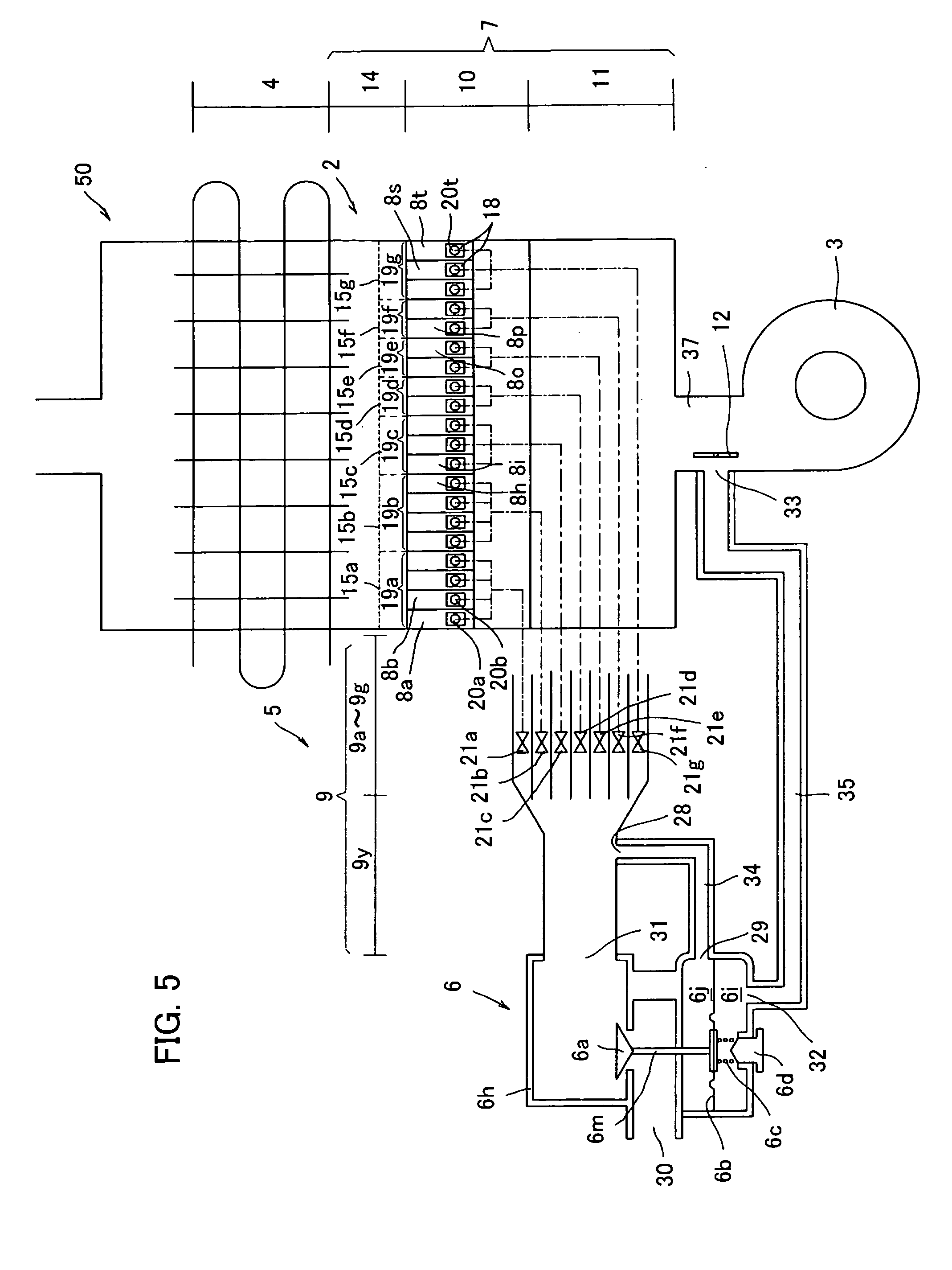
[0115] A combustion apparatus 50 shown in FIG. 5 is provided with a pressure modification board (pressure modification means) 12 adjacent to the signal-pressure outlet 33 and at a position opposite the outlet 33. The pressure modification board 12 is designed to either increase or decrease a signal pressure detected at the outlet 33.
[0116] The pressure modification board 12 is a rectangular thin plate and rotates so that ends of the board 12 in a longitudinal direction come close to or move apart from the outlet 33 around its center in a longitudinal direction. The board 12 controls to change an angle formed by the intersection with an air flowing direction of the air supply passage 37, thereby either increasing or decreasing a signal pressure to be introduced into the pressure regulator 6. Further, the board 12 is powered by a known stepping motor (pressure modification means or actuator) not shown. Driving of the stepping motor rotates the pressure modification board 12. Herein, the stepping motor is controlled by a controller not shown and is driven upon reception of a signal from the controller.
[0117] The combustion apparatus 50 in this embodiment is designed to detect a signal pressure in the pressure regulator 6 at the outlet of the air feeder 3 and regulates a secondary pressure in the common channel 9y connected to the pressure regulator 6 in accordance with the detected signal pressure. Further, in the combustion apparatus 50, the pressure modification board 12 is disposed at the air supply passage 37, so as to modify the signal pressure detected at the signal-pressure outlet 33.
[0118] In this embodiment, as shown in FIG. 6A, one end (downstream side in the air feeding direction) of the board 12 is arranged to move slightly close to the signal-pressure outlet 33 (position in a stable combustion), so as to slightly direct an air flow to the outlet 33, thereby controlling the air-fuel ratio in the normal combustion by the action of a slight dynamic pressure. In order to increase the signal pressure detected at the outlet 33, as shown in FIG. 6B, the board 12 is controlled to rotate in a direction closer to the outlet 33 (direction with a larger angle formed by the intersection of the board 12 with the air flowing direction in the air supply passage 37), so that more air flows to the outlet 33 (position in an increased dynamic pressure). That increases a dynamic pressure acting to the position where the pressure is detected. In contrast, in order to decrease the signal pressure detected at the outlet 33, as shown in FIG. 6C, the board 12 is controlled to rotate in a direction away from the outlet 33 (direction with a smaller angle formed by the intersection of the board 12 with the air flowing direction in the air supply passage 37), so that less air flows toward the outlet 33 (position in a decreased dynamic pressure). That decreases a dynamic pressure acting to the position where the pressure is detected.
[0119] Therefore, the pressure modification board 12 is designed to modify an original signal pressure having been detected at the air feeder 3 so as to introduce the modified signal pressure into the pressure regulator 6. More specifically, as shown in FIG. 6B, a control of the board 12 so as to direct air to the signal-pressure outlet 33 increases a signal pressure to be introduced into the signal-pressure inlet 32 without increasing the number of rotations of the air feeder 3, thereby supplying fuel gas in an amount in response to the increased signal pressure to the fuel supply channel 9. That enables a control to have a higher ratio of fuel gas than the air-fuel ratio in the normal combustion. Consequently, the combustion apparatus 50 in this embodiment improves ignition performance in ignition and reduces an oscillating combustion that is possibly generated within a certain period of time after ignition and an unstable combustion that is possibly generated in increasing the combustion amount in the normal combustion by opening of some of the shutoff valves 21a to 21g.
[0120] Further, as shown in FIG. 6C, a control of the board 12 so that less air flows toward the outlet 33 than that in the normal combustion allows an original signal pressure (static pressure) in response to the number of rotations of the air feeder 3 to be introduced into the pressure regulator 6, thereby supplying fuel gas in an amount in response to the signal pressure (static pressure) to the fuel supply channel 9. That enables a control to have a lower ratio of fuel gas than the air-fuel ratio in the normal combustion. Consequently, the combustion apparatus 50 in this embodiment reduces an oscillating combustion that is possibly generated within a certain period of time after ignition and an unstable combustion that is possibly generated in decreasing the combustion amount in the normal combustion by closing of some of the shutoff valves 21a to 21g.
[0121] Still further, this embodiment allows either pseudo increase or decrease of a signal pressure introduced into the signal-pressure inlet 32 by a control of the board 12. Consequently, the amount of fuel gas flowing in the fuel supply channel 9 is either increased or decreased by the pseudo signal pressure, whereby the air-fuel ratio is modified. The combustion apparatus 50 in this embodiment not only maintains a constant air-fuel ratio but also performs practical combustion as described above by modifying the air-fuel ratio as needed.
[0122] The above-mentioned embodiment illustrates a configuration in which the pressure modification board 12 is provided adjacent to the signal-pressure outlet 33 so as to modify a signal pressure, but the present invention is not limited thereto and may have a configuration in which the pressure modification board 12 is provided in the fuel flowing channel.
[0123] As shown in a combustion apparatus 70 in FIG. 7, for example, in a case where a secondary pressure to be introduced into the pressure regulator 6 is detected at the secondary-pressure outlet 28 provided adjacent to the fuel common channel 9, the pressure modification board 12 is arranged adjacent to the outlet 28. The board 12 is arranged in the substantially same manner as that in the above-mentioned embodiment. Specifically, the board 12 is arranged so as to slightly direct a flow of fuel gas to the secondary-pressure outlet 28 for making a dynamic pressure to be detected. The way to control of either increase or decrease of the amount of fuel gas is slightly different from that in the above-mentioned embodiment, being described in detail below.
[0124] In the case of arrangement of the pressure modification board 12 near a position where the secondary pressure is detected, a control of the board 12 to direct a flow of fuel gas to the secondary-pressure outlet 28 makes the secondary pressure detected at the outlet 28 higher than an original secondary pressure of fuel gas actually flowing in the fuel supply channel 9. The pseudo secondary pressure (dynamic pressure) introduced into the pressure regulator 6 is regulated in accordance with the signal pressure from the air feeder 3, so that fuel gas supplied to the combustion space 14e has a lower ratio than the air-fuel ratio in the normal combustion. Such a control provides an effect similar to that obtained by detecting the static pressure by controlling the board 12 to rotate so that less air flows to the signal-pressure outlet 33 as described in the above-mentioned embodiment.
[0125] Further, the control of the board 12 so that less fuel gas flows toward the secondary-pressure outlet 28 allows the secondary pressure detected at the outlet 28 to be the original secondary pressure of fuel gas having been discharged in accordance with the signal pressure. Specifically, the pseudo secondary pressure (static pressure) introduced into the pressure regulator 6 is regulated in accordance with the signal pressure from the air feeder 3, and whereby fuel gas supplied to the combustion space 14 has a higher ratio than the air-fuel ratio in the normal combustion. Such a control provides an effect similar to that obtained by detecting the dynamic pressure by controlling the board 12 to rotate so as to direct an air flow to the signal-pressure outlet 33 as described in the above-mentioned embodiment.
[0126] Consequently, by this configuration, the control of the pressure modification board 12 regulates fuel gas having a ratio shifted from the air-fuel ratio in the normal combustion, as needed, thereby providing an effect similar to that obtained by the above-mentioned embodiment.
[0127] The above-mentioned embodiment illustrates a configuration in which the pressure modification board 12 is powered by the stepping motor as the actuator not shown, but the present invention is not limited thereto and may have a configuration in which the board 12 is powered by a servomotor or a motor with a limit switch.
[0128] The above-mentioned embodiment illustrates a configuration in which the pressure modification board 12 is controlled in three steps: the position in the stable combustion; the position in the increased dynamic pressure; and the position in the decreased dynamic pressure, but the present invention is not limited thereto and may have a configuration having at least one additional step between the positions in the increased dynamic pressure and the decreased dynamic pressure.
[0129] The above-mentioned embodiment illustrates a configuration in which the pressure modification board 12 is controlled to be at the position in the decreased dynamic pressure until a certain period of time passes after ignition, but the present invention is not limited thereto and may have a configuration in which the board 12 is controlled to be at the position in the increased dynamic pressure. Shortly, it is enough only to reduce an unstable combustion such as an oscillating combustion that is possibly generated until the combustion is stabilized after ignition.
[0130] By the above-mentioned embodiment, a change of the number of burners to be used for combustion provides no change of the ratio of air and fuel supplied to the burners and achieves a stable combustion. Yet, the combustion might be temporally unstable immediately after the change of the numbers of burners to be used for combustion.
[0131] The reason for such a case would be as follows. The pressure regulators 6 employed in the combustion apparatuses 1 and 50 described above each regulate a secondary pressure of fuel gas so that a pressure introduced through the signal-pressure inlet 32 becomes substantially equal to a discharge pressure of the fuel gas from the pressure regulator 6. However, when the combusting area is decreased by closing of some of the shutoff valves 21a to 21g, the secondary pressure in the common channel 9y in the fuel supply channel 9 is temporally increased, resulting in temporally increasing of the amount of the fuel gas flowing in the remaining branched channels 9a to 9g having the remaining opened shutoff valves 21a to 21g. As described above, in each of the combustion apparatuses 1 and 50, the pressure regulator 6 regulates the increased secondary pressure in accordance with the signal pressure, but it takes a certain period of time to regulate the secondary pressure in accordance with the signal pressure. As a result, the fuel gas has excessively high concentration in the combustion space 14 until regulated, resulting in an unstable combustion.
[0132] Research and studies of the above-mentioned problem revealed that it is because the slow movement of a main valve of a pressure regulator to a closed side (in a direction to narrow an open area), the movement being performed in accordance with pressure increase of fuel gas within a fuel supply channel.
[0133] Specifically, the pressure regulator has the main valve, which is operated so as to either increase or decrease an effective area in which fuel gas flows in the fuel gas passage, thereby regulating a pressure at the outlet to a predetermined pressure.
[0134] More specifically, the main valve of the pressure regulator is operated by a diaphragm or a bellows, each of which has a predetermined working-fluid chamber. A pressure in the chamber is either increased or decreased by a working fluid flowing into the chamber, thereby expanding or contracting the diaphragm or the bellows so as to operate the main valve. The working fluid is normally a gas, especially air in a pressure regulator of a direct acting type and fuel gas in a pressure regulator of a pilot type.
[0135] Upon pressure increase of fuel gas in the fuel supply channel, the main valve is moved to the closed side so as to decrease the pressure of fuel gas discharged from the pressure regulator, so that the pressure in the fuel supply channel is returned to a normal level. For doing that, it is necessary to eliminate a part of the working fluid within the working-fluid chamber so as to contract the diaphragm or the bellows. However, the previously produced combustion apparatus could not smoothly eliminate the working fluid from the chamber, resulting in taking time to contract that. As a result, excessively high pressure in the fuel supply channel persisted over a period of time, causing an unstable combustion.
[0136] Therefore, with a configuration in which a working-fluid supply part (air supply part) is temporally closed to close a passage for supplying the fluid to the chamber so as to facilitate the elimination of the fluid from the chamber when the combusting area is decreased by closing of shutoff valves, a stable combustion is maintained even immediately after changing of the number of burners.
[0137] A further modified combustion apparatus in an embodiment described below has a pressure regulator provided with a main valve for either increasing or decreasing an open area in a main passage of fuel gas and a main-valve drive mechanism for operating the main valve. The main-valve drive mechanism includes a working-fluid chamber, a working-fluid supply part, and a leak channel, so as to operate the main valve by supplying a working fluid to the working-fluid chamber having passed through the supply part. The supply part is temporally closed simultaneously with closing the shutoff valves so as to reduce the combusting area, thereby stopping supply of the working fluid to the chamber.
[0138] The leak channel is designed to leak the working fluid, which is supplied from the supply part, from the working-fluid chamber. Closing of the supply part stops supply of the working fluid to the chamber and further allows the working fluid within the chamber to be leaked through the leak channel, thereby decreasing a pressure in the chamber. That makes the main valve to move to decrease the open area, so as to rapidly decrease a secondary pressure of fuel gas. Thus, by the combustion apparatus in this embodiment, temporally closing of the working-fluid supply part blocks the working fluid from flowing into the working-fluid chamber and further allows the working fluid within the chamber to leak via the leak channel, thereby rapidly decreasing the secondary pressure. Consequently, even when some of the shutoff valves are closed so as to decrease the combusting area, the time to regulate the secondary pressure in the fuel supply channel to an appropriate secondary channel is shortened.
[0139] The combustion apparatus in this embodiment is designed only to temporally increase the leak amount of the working fluid so as to shorten the time required for returning the secondary pressure within the fuel supply channel to a normal level. Thus, the working-fluid supply part is opened immediately after the closing, so that the secondary pressure is regulated to an appropriate secondary pressure in accordance with a signal pressure. Consequently, even when the combusting area is reduced by closing of the shutoff valves, the combustion apparatus in this embodiment shortens the time to regulate the secondary pressure to an appropriate secondary pressure and maintains an appropriate air-fuel ratio, thereby reducing an unstable combustion.
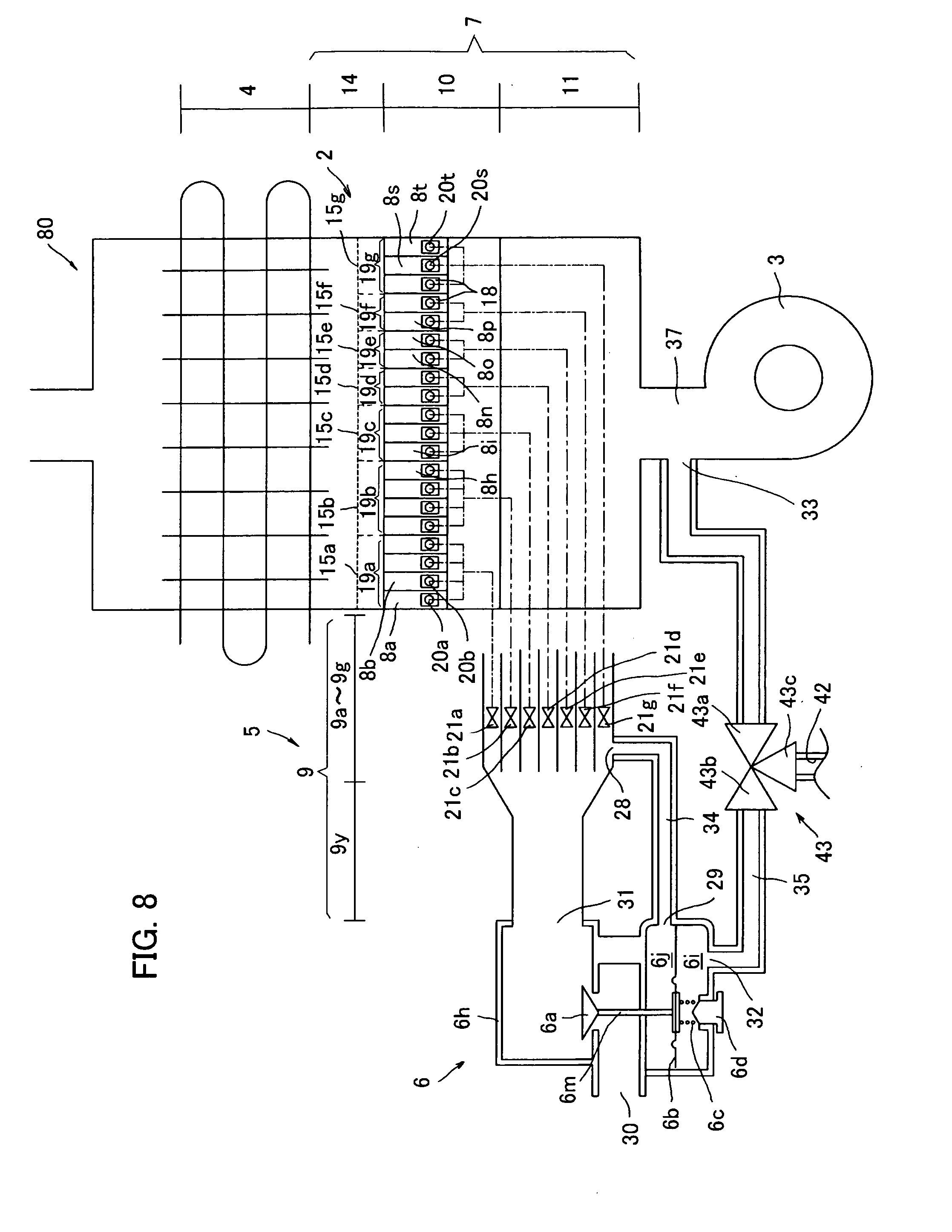
[0140] FIG. 8 is a configuration diagram showing a combustion apparatus having the above-mentioned embodiment.
[0141] The combustion apparatus 80 shown in FIG. 8 has a configuration in which a secondary-pressure conducting pipe (working-fluid supply part) 35 for conducting a signal pressure from the air feeder 3 is provided with a three-way valve 43. The three-way valve 43 has connecting ports 43a and 43b in two directions, the ports 43a and 43b forming a part of the conducting pipe 35, and a connecting port 43c in the rest one direction, the port 43c being connected to a temporary leak channel 42. The working fluid is air from the air feeder 3.
[0142] In order to reduce the combusting area by closing of some of the shutoff valves 21a to 21g, the three-way valve 43 is temporally switched at the same time of the closing of the shutoff valves. Specifically, the three-way valve 43 is switched so as to make the connecting port 43b to be communicated with the connecting port 43c, thereby leaking the working fluid within a working-fluid chamber 6i in the pressure regulator 6. That stops introducing the signal pressure into the working-fluid chamber 6i, thus moving a diaphragm 6b in the pressure regulator 6 downwardly and also a main valve 6a downwardly. That narrows an area through which fuel gas flows, thereby decreasing the secondary pressure. Consequently, by this configuration, forcible stop to introduce the signal pressure into the pressure regulator 6 shortens the time to temporally increase the secondary pressure, thereby reducing an unstable combustion even when the combusting area is reduced using the shutoff valves 21.
* * * * *
D00000
D00001
D00002
D00003
D00004
D00005
D00006
D00007
D00008
D00009
XML
uspto.report is an independent third-party trademark research tool that is not affiliated, endorsed, or sponsored by the United States Patent and Trademark Office (USPTO) or any other governmental organization. The information provided by uspto.report is based on publicly available data at the time of writing and is intended for informational purposes only.
While we strive to provide accurate and up-to-date information, we do not guarantee the accuracy, completeness, reliability, or suitability of the information displayed on this site. The use of this site is at your own risk. Any reliance you place on such information is therefore strictly at your own risk.
All official trademark data, including owner information, should be verified by visiting the official USPTO website at www.uspto.gov. This site is not intended to replace professional legal advice and should not be used as a substitute for consulting with a legal professional who is knowledgeable about trademark law.