Forged Beryllium-copper Bulk Material
MURAMATSU; Naokuni
U.S. patent application number 12/880429 was filed with the patent office on 2010-12-30 for forged beryllium-copper bulk material. This patent application is currently assigned to NGK Insulators, Ltd.. Invention is credited to Naokuni MURAMATSU.
| Application Number | 20100329923 12/880429 |
| Document ID | / |
| Family ID | 41113443 |
| Filed Date | 2010-12-30 |


| United States Patent Application | 20100329923 |
| Kind Code | A1 |
| MURAMATSU; Naokuni | December 30, 2010 |
FORGED BERYLLIUM-COPPER BULK MATERIAL
Abstract
The present invention provides a forged beryllium-copper bulk material, wherein the hardness of the central portion is 0 to 10% higher than that of the front surface, the Vickers hardness of the central portion is 240 or more, the tensile strength is 800 N/mm.sup.2 or more, and the bulk material having uniformity to such an extent that variation in measured values of the tensile strength in arbitrary directions is within 5%.
| Inventors: | MURAMATSU; Naokuni; (Nagaoya-City, JP) |
| Correspondence Address: |
    BURR & BROWN
    PO BOX 7068
    SYRACUSE
    NY
    13261-7068
    US
|
| Assignee: | NGK Insulators, Ltd. Nagaoya-City JP |
| Family ID: | 41113443 |
| Appl. No.: | 12/880429 |
| Filed: | September 13, 2010 |
Related U.S. Patent Documents
| Application Number | Filing Date | Patent Number | ||
|---|---|---|---|---|
| PCT/JP2009/053449 | Feb 25, 2009 | |||
| 12880429 | ||||
| Current U.S. Class: | 420/485 ; 420/494 |
| Current CPC Class: | C22C 9/00 20130101; C22F 1/08 20130101; C22C 9/06 20130101 |
| Class at Publication: | 420/485 ; 420/494 |
| International Class: | C22C 9/06 20060101 C22C009/06; C22C 9/00 20060101 C22C009/00 |
Foreign Application Data
| Date | Code | Application Number |
|---|---|---|
| Mar 28, 2008 | JP | 2008-087628 |
Claims
1. A forged beryllium-copper bulk material, at least comprising Be and Cu, the hardness of the central portion being 0 to 10% higher than that of the front surface, the Vickers hardness of the central portion being 240 or more, the tensile strength being 800 N/mm.sup.2 or more, and the bulk material having uniformity to such an extent that variation in measured values of the tensile strength in arbitrary directions being within 5%.
2. The forged beryllium-copper bulk material according to claim 1, wherein the tensile strength in three forging directions that are orthogonal to each other and the tensile strength measured, on a plane including two forging directions that are orthogonal to each other, in a direction making an angle of 45.degree. with the two forging directions are 1100 N/mm.sup.2 or more.
3. The forged beryllium-copper bulk material according to claim 1, comprising a weight ratio of Cu.sub.100-(a+b)Be.sub.aCo.sub.b (0.4%.ltoreq.a.ltoreq.2.0%, 0.15%.ltoreq.b.ltoreq.2.8%, a+b.ltoreq.3.5%) or a weight ratio of Cu.sub.100-(c+d)Be.sub.cNi.sub.d (0.05%.ltoreq.c.ltoreq.0.6%, 1.0%.ltoreq.d.ltoreq.2.4%, c+d.ltoreq.3.0%), wherein, Fe, S and P as impurities are limited to be lower than 0.01% in terms of the weight ratio.
4. The forged beryllium-copper bulk material according to claim 1, wherein the Vickers hardness of the central portion is 240 to 450 and the tensile strength is 1100 to 1500 N/mm.sup.2.
5. The forged beryllium-copper bulk material according to claim 1, comprising grains having an average grain size of 2 .mu.m or lower, wherein the grains do not contain a shear band structure crossing a plurality of grains and are stable in the shape, and have a precipitated phase including the Be precipitated from the Cu.
6. The forged beryllium-copper bulk material according to claim 2, comprising a weight ratio of Cu.sub.100-(a+b)Be.sub.aCo.sub.b (0.4%.ltoreq.a.ltoreq.2.0%, 0.15%.ltoreq.b.ltoreq.2.8%, a+b.ltoreq.3.5%) or a weight ratio of Cu.sub.100-(c+d)Be.sub.cNi.sub.d (0.05%.ltoreq.c.ltoreq.0.6%, 1.0%.ltoreq.d.ltoreq.2.4%, c+d.ltoreq.3.0%), wherein Fe, S and P as impurities are limited to be lower than 0.01% in terms of the weight ratio.
7. The forged beryllium-copper bulk material according to claim 2, wherein the Vickers hardness of the central portion is 240 to 450 and the tensile strength is 1100 to 1500 N/mm.sup.2.
8. The forged beryllium-copper bulk material according to claim 2, comprising grains having an average grain size of 2 .mu.m or lower, wherein the grains do not contain a shear band structure crossing a plurality of grains and are stable in the shape, and have a precipitated phase including the Be precipitated from the Cu.
Description
TECHNICAL FIELD
[0001] The present invention relates to forged beryllium bulk material.
BACKGROUND ART
[0002] Beryllium copper bulk materials are used for machine structural components in which durability and reliability are demanded, such as bearings for airplanes, casings for under sea cable repeaters, rotor shafts for ships, collars of oil field drilling drills, injection molding dies, or welding electrode holders. In general, the applications require machinability and high hardness or strength of bulk materials.
[0003] Beryllium copper is a precipitation-hardening copper alloy similarly as many high strength copper alloys, and bulk materials thereof are manufactured through forging-homogenization annealing-hot working-solution annealing (solid solution treatment)-water quenching-age hardening, which is well-known to persons skilled in the art. For example, Patent Document 1 discloses that grains are fined to a certain degree by carefully selecting conditions of each treatment, and an increase in strength and an improvement of a fatigue life, which are important for the machine structural components, are achieved. Patent Document 2 discloses that grains can be fined to a degree that has not been found in former cases by extensively examining a forging method and treatment conditions during forging.
[0004] However, in the methods described in Patent Documents 1 and 2, differences in the temperatures between the near-surface portions and the center core portion during water quenching cannot be disregarded, and thus the strength (hardness) of the center core portion which is hard to be cooled decreases compared with the near-surface portions. Thus, when processing various components by cutting from the obtained member, the residual stress due to unbalanced strength remaining in which the strength varies depending on portions of the member is released, and thus the component has been distorted during cutting in some cases. Moreover, there has been a problem in that the fatigue life is likely to become short.
[0005] As described in JIS G4052 (Structural steels with specified hardenability), the cause of such a phenomenon is presumed also from the fact that values indicating the hardness notably decrease with an increase in the dimension distance of bulk materials from the surface portions to the inside. The phenomenon such that the hardness values become lower from the front surface toward the inside is a problem common to bulk materials of copper alloy prepared through water quenching after heat treatment without being limited to steel materials, and has notably appeared with an increase in the size of bulk materials.
[0006] [Patent Document 1] Japanese Patent No. 2827102
[0007] [Patent Document 2] Japanese Unexamined Patent Application Publication No. 2005-096442
DISCLOSURE OF INVENTION
[0008] In view of the above-described problem, it is an object of the present invention to provide a forged beryllium-copper bulk material that maintains uniform hardness from the front surface to the inside, has high reliability, is excellent in a fatigue life, and is hard to cause distortion during processing.
[0009] The present invention provides a forged beryllium-copper bulk material, at least including Be and Cu,
[0010] the hardness of the central portion being 0 to 10% higher than that of the front surface,
[0011] the Vickers hardness of the central portion being 240 or more,
[0012] the tensile strength being 800 N/mm.sup.2 or more, and
[0013] the bulk material having uniformity to such an extent that variation in measured values of the tensile strength in arbitrary directions being within 5%.
[0014] The invention provides a forged beryllium-copper bulk material that maintains uniform hardness from the front surface to the inside, has high reliability, is excellent in a fatigue life, and is hard to cause distortion during processing.
BRIEF DESCRIPTION OF DRAWINGS
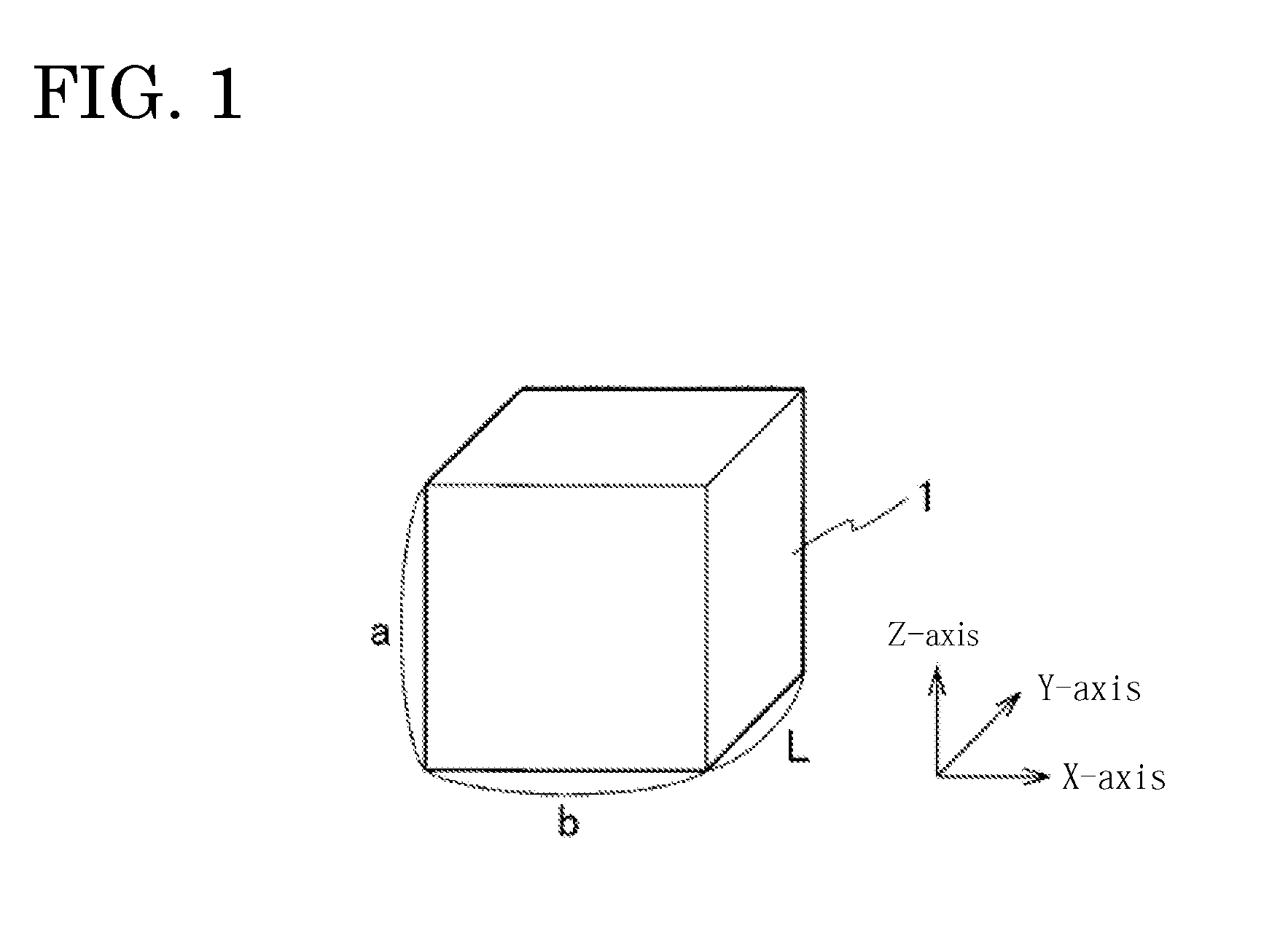
[0015] FIG. 1 is a perspective view showing a forged beryllium-copper bulk material according to one embodiment of the invention.
[0016] FIG. 2 is a flow chart showing a method for manufacturing a forged beryllium-copper bulk material according to one embodiment of the invention.
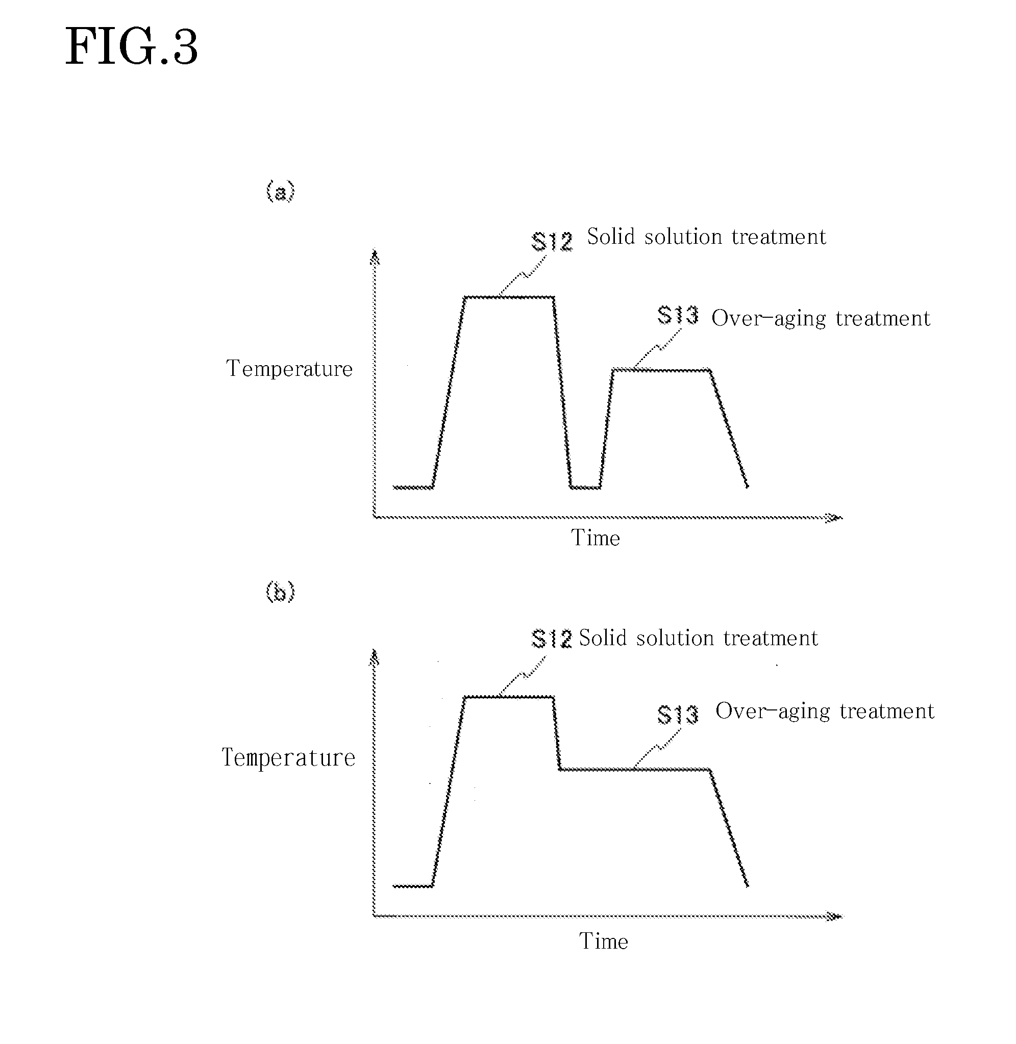
[0017] FIG. 3(a) is a graph showing the relationship between the treatment time and the temperature when the solid solution treatment and the over-aging treatment of FIG. 2 are discontinuously carried out and FIG. 3(b) is a graph showing the relationship between the treatment time and the temperature when the solid solution treatment and the over-aging treatment are continuously carried out.
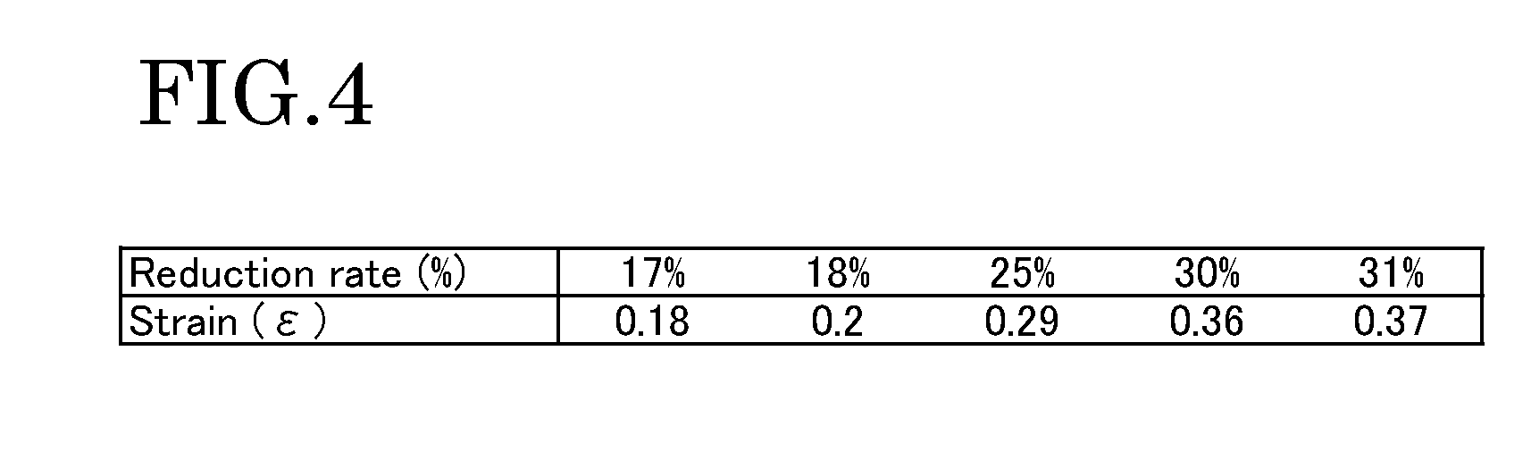
[0018] FIG. 4 is a table showing the relationship between the size reduction rate and the strain according to one embodiment of the invention.
[0019] FIG. 5(a) is a view showing the appearance of a forged beryllium-copper bulk material according to one embodiment of the invention, FIG. 5(b) is a graph showing the relationship between a pressure and a cumulative strain during repeated pressurization at a size reduction rate of 18%, and FIG. 5(c) is a table showing changes in the surface temperature immediately after the repeated pressurization.
[0020] FIG. 6(a) is a view showing the appearance of a former forged beryllium-copper bulk material, FIG. 6(b) is a graph showing the relationship between a pressure and a cumulative strain during repeated pressurization at a size reduction rate of 33%, and FIG. 6(c) is a table showing changes in the surface temperature immediately after the repeated pressurization.
[0021] FIG. 7(a) is a perspective view showing a test piece when measuring the hardness of a forged beryllium-copper bulk material, FIG. 7(b) is a graph showing the relationship between the distance from a surface plane to the center plane and the Vickers hardness of a beryllium bulk material according to one embodiment of the invention immediately after cold forging treatment, and FIG. 7(c) is a graph showing the relationship between the distance from a surface plane to the center plane and the Vickers hardness of a beryllium bulk material according to one embodiment of the invention after age hardening treatment.
[0022] FIG. 8 is a graph showing the relationship between the distance from a surface plane to the center plane and the Vickers hardness of a former beryllium bulk material.
[0023] FIG. 9 is a schematic view showing distortion after processing measurement results of a forged beryllium-copper bulk material according to one embodiment of the invention and a former forged beryllium-copper bulk material.
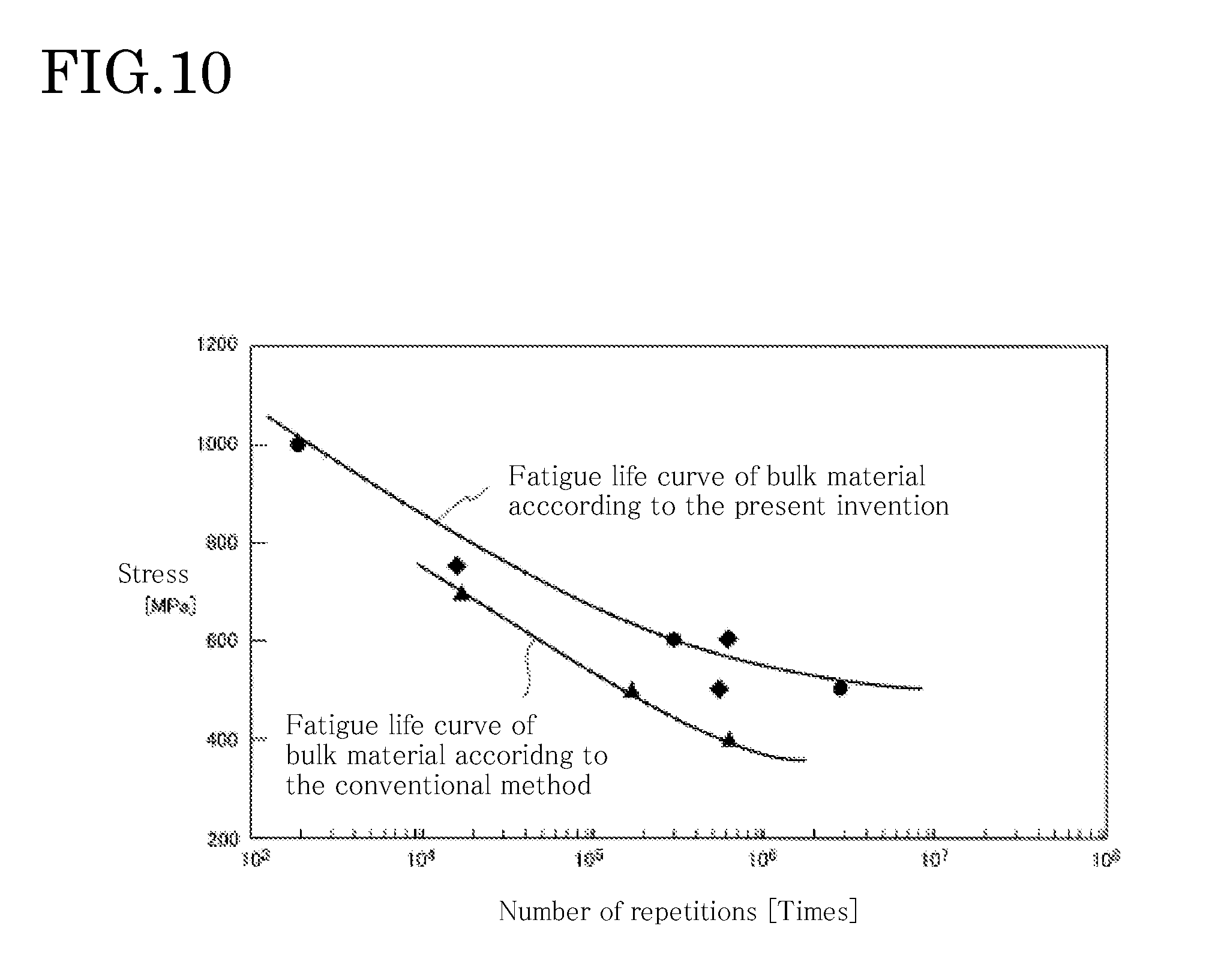
[0024] FIG. 10 is a graph showing a fatigue life curve of a forged beryllium-copper bulk material according to one embodiment of the invention.
[0025] FIG. 11 is a graph showing an example of ultrasonic inspection test results of a forged beryllium-copper bulk material according to one embodiment of the invention and a former beryllium-copper bulk material.
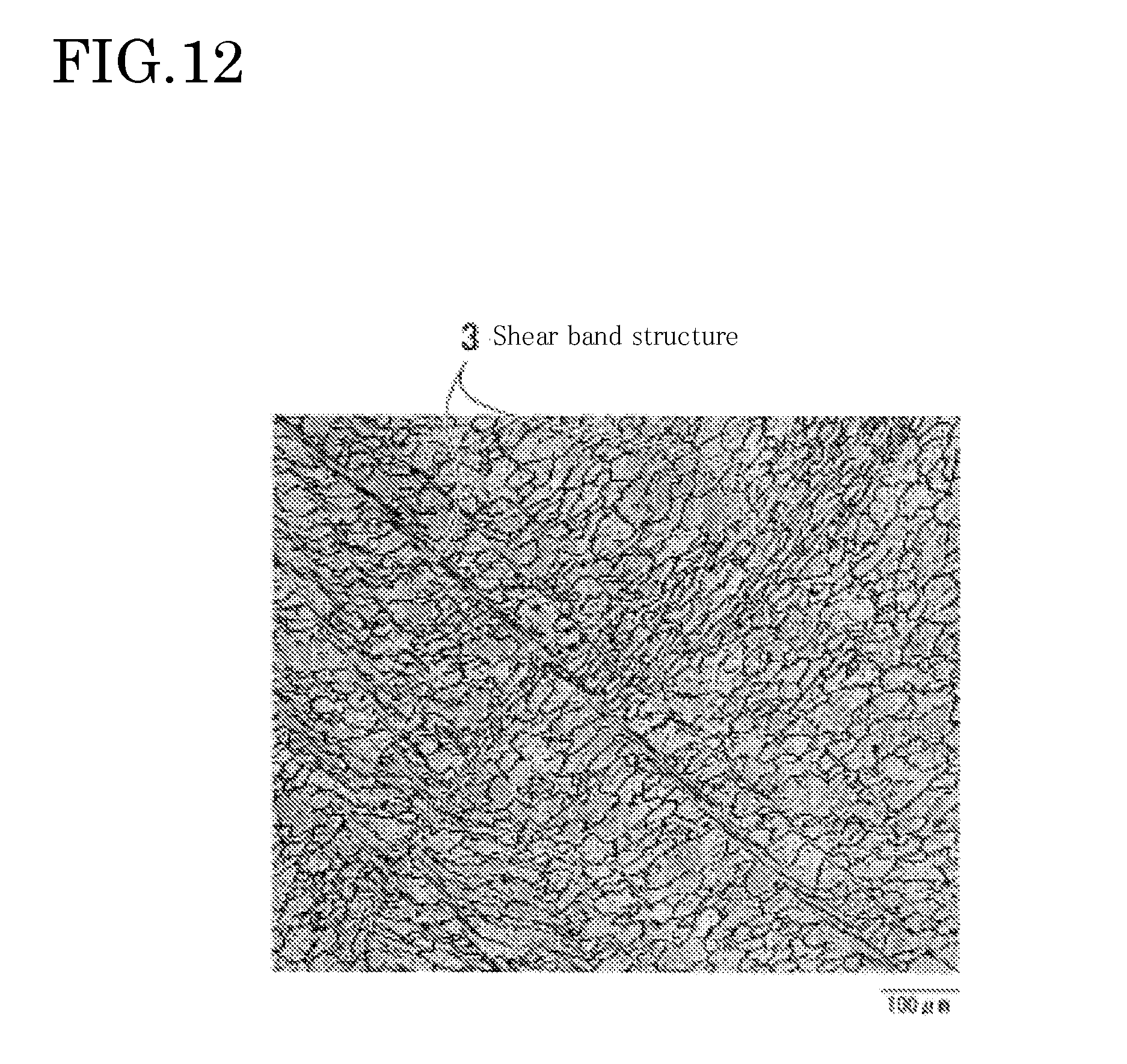
[0026] FIG. 12 is a view showing observation results of a shear band structure crossing a plurality of grains in a beryllium-copper bulk material in a comparative example.
BEST MODES FOR CARRYING OUT THE INVENTION
[0027] Next, embodiments of the present invention will be described with reference to the drawings. In the following description of the drawings, the same or similar parts are designated by the same or similar reference numerals. The following embodiments describe examples of devices and methods for putting the technical idea of this invention into effect, and, according to the technical idea of this invention, the structure, arrangement, and the like of constitutional components are not limited to the following ones.
[0028] (Forged Beryllium-Copper Bulk Material)
[0029] As shown in FIG. 1, a forged beryllium-copper bulk material 1 according to the embodiment of the invention is an alloy containing beryllium (Be) and copper (Cu) and is a rectangular parallelepiped shaped alloy having the sides of a, b, and L extending along the directions of the three axes (Z axis, X-axis, and Y-axis of FIG. 1) that are orthogonal to each other.
[0030] The ratio of the length of the sides a, b, and L of the forged beryllium-copper bulk material 1 is not particularly limited. For example, a cubic shape of a:b:L=1:1:1 is acceptable. The size of the forged beryllium-copper bulk material 1 is not particularly limited. However, when the dimension of the sides a, b, and L becomes excessively large, it becomes difficult to control the manufacturing conditions described later due to influences of process heat generation from the forged beryllium-copper bulk material 1 during forging. Thus, with respect to the dimension of the forged beryllium-copper bulk material 1, the a, b, and L can be adjusted in the range of about 50 to 500 mm and preferably 80 to 400 mm, for example.
[0031] The forged beryllium copper bulk material 1 has (1) a weight ratio of Cu.sub.100-(a+b)Be.sub.aCo.sub.b (0.4%.ltoreq.a.ltoreq.2.0%, 0.15%.ltoreq.b.ltoreq.2.8%, a+b.ltoreq.3.5%) or (2) a weight ratio of Cu.sub.100-(a+b)Be.sub.aCo.sub.b (0.4%.ltoreq.a.ltoreq.2.0%, 0.15%.ltoreq.b.ltoreq.2.8%, a+b.ltoreq.3.5%) and the content of Fe, S, and P as impurities is preferably limited to lower than 0.01% in terms of the weight ratio.
[0032] In (1) above, the weight ratio of Be is adjusted to 0.4% or more for increasing the strength by a precipitated phase constituted by Be and Cu and/or Be and Co. The weight ratio of Be is adjusted to 2.0% or lower for increasing the strength by suppressing coarsening of a precipitated phase constituted by Be and Co. The weight ratio of Co is adjusted to 0.15% or more for increasing the strength by adding Co. The weight ratio of Co is adjusted to 2.8% or lower for suppressing coarsening of a precipitated phase constituted by Be and Co.
[0033] In contrast, the combination of (2) is used for the weight ratio of the forged beryllium-copper bulk material 1 to reduce the ratio of Be for reducing the material cost by adding Ni, which is less expensive than Be. Specifically, the weight ratio of Be is adjusted to 0.05% or more for increasing the strength by a precipitated phase constituted by Be and Ni. The weight ratio of Be is adjusted to 0.6% or lower for sufficiently obtaining the effect of reducing the cost by reducing the weight ratio of Be. The weight ratio of Ni is adjusted to 1.0% or more for increasing the strength by adding Ni. The weight ratio of Ni is adjusted to 2.4% or lower for suppressing a reduction in electrical conductivity or an increase in the melting point due to Ni contained in a matrix of Cu.
[0034] The content of Fe, S, and P as impurities is limited to be lower than 0.01% in terms of weight ratio because, the elements are likely to be segregated in the grain boundary when these elements are contained in a proportion of 0.01% or more, and thus a product is likely to break during forging treatment.
[0035] The forged beryllium-copper bulk material 1 of FIG. 1 has a fine grain structure (average grain size.ltoreq.2 .mu.m) and has a precipitated phase at least containing Be which is precipitated from Cu. Here, the "average grain size" refers to an average grain size measured by the following measurement method.
[0036] (A) Conduct crystal orientation analysis using an SEM/EBSP (Scanning Electron Microscope/Electron Back Scatter Diffraction Pattern) method, and count boundaries with an misorientation angle .theta. of 2.degree. or larger as grain boundaries to obtain a distribution of grain sizes.
[0037] (B) Confirm that the average misorientation angle .theta. is 15.degree. or larger in the total count.
[0038] (C) Calculate an average grain size from the distribution of grain sizes.
[0039] In general, structures constituted only by sub-grains having an misorientation angle .theta. of 0.degree..ltoreq..theta.<4.degree. are not counted as crystal grains. However, in this embodiment, since an observation result is a capture of an arbitrary moment of a process of ultra-fining, structures constituted only by sub-grains having an misorientation angle .theta. of 0.degree..ltoreq..theta.<4.degree. are also considered to form a part of the entire structure at that moment. Therefore, structures having an misorientation angle of 15.degree. or larger are counted as grains.
[0040] The forged beryllium-copper bulk material 1 is an alloy in which the hardness is uniform (or becomes gradually harder) from the near-surface portions to the center core portion, the hardness of the central portion is 0 to 10% higher than that of the front surface, the Vickers hardness (HV) of the front surface (end portion) is 218 to 450 and more preferably 273 to 450, and the Vickers hardness of the internal center is 240 to 450 and more preferably 300 to 450. The "Vickers hardness" in this embodiment refers to a measurement result obtained as follows. For example, a plate 2 that is cut in parallel to the direction of the X-Z plane in such a manner as to include the center of the forged beryllium-copper bulk material 1 in the form of a rectangular parallelepiped (cube) shown in FIG. 7(a) is used as a test piece, and then an arbitrary point on the test piece is measured according to JISZ2244 (Vickers hardness test method-Test method (Corresponding international standard; ISO/6507-1; 1995 Metallic materials-Vickers hardness test-Part 1; Test Method).
[0041] The forged beryllium-copper bulk material 1 is a polycrystal having no anisotropy in the orientation (random orientation) from the hardness, structure, ultrasonic inspection test, observation results of the grains by the EBSP method described later, and the tensile strength is 800 N/mm.sup.2 or more, preferably 800 to 1500 N/mm.sup.2, more preferably 1100 to 1500 N/mm.sup.2, and still more preferably 1100 to 1300 N/mm.sup.2. When the tensile strength is made smaller than 800 N/mm.sup.2, the mechanical strength or the fatigue life decreases, and thus the forged beryllium-copper bulk material 1 is not accepted in the market of machine structural components in some cases.
[0042] The tensile strength values of the beryllium forge bulk material 1 are isotropic (uniform) in an arbitrary forging direction or in a direction making an angle of 45.degree. within the plane including the arbitrary forging direction and the variation in the measured tensile strength values (measurement average value) was within 5%.
[0043] The measurement method of the tensile strength is as follows. First, plates containing the X-Y plane, the Y-Z plane, and the X-Z plane were cut out from the center of the beryllium forge bulk material 1, and then tensile test pieces were machined so that six directions (i.e., X, Y, Z, X-Y with an angle of 45.degree., Y-Z with an angle of 45.degree., and X-Z with an angle of)45.degree. which represent arbitrary directions correspond with the tensile axis from each plate. The test pieces were produced according to JISSZ2201, but the test pieces in which the dimension was reduced to 1/2 due to the restriction of the size of raw materials were used. The produced test pieces were measured according to JISZ2241 (Method of tensile test for metallic materials).
[0044] The reason for selecting the six directions as the arbitrary directions resides in the fact that, when machine structural articles are produced from the forged beryllium-copper bulk material 1, the articles are usually produced based on the plane in which the forging direction is the normal line and the tensile stress mechanically applied in the X, Y, and Z directions are important for products.
[0045] The stress in the X, Y and Z directions are known to theoretically originate from the shearing strength in the direction of 45.degree. to the X, Y and Z directions ("Zairyo Kogaku Nyumon" jointly translated by Ryo Horiuchi, Junichi Kaneko, and Masahisa Otsuka; Uchida-Rokakuho Publishing Co., 3rd edition, 1990, p 123-142 or Original: M. F. Ashby and D. R. H. Jones "Engineering Materials" PERGAMON PRESS; 1980). In addition, when the tensile strength applied in the direction of 45.degree. to the X, Y, and Z directions is measured, the shearing strength in the direction of further 45.degree. (in the X, Y, and Z directions) from the point is measured.
[0046] When the forged beryllium-copper bulk material 1 is anisotropic in the direction shifted from the X, Y, and Z directions only by specific angles of .alpha., .beta., and .gamma. (specific directions having a particularly low strength), abnormal values should be observed in some of the six directions insofar as the forged beryllium-copper bulk material 1 is a polycrystal. However, the variation in the tensile strength value when measured in the six directions is within 5% in this embodiment, and no abnormal values were measured. Thus, it can be said that the forged beryllium-copper bulk material 1 according to this embodiment has isotropy (uniformity) in the tensile strength in any arbitrary direction and that the values are almost the same.
[0047] (Method for Manufacturing Forged Beryllium-Copper Bulk Material)
[0048] Next, a method for manufacturing a forged beryllium-copper bulk material according to the embodiment of the invention will be described with reference to the flow charts shown in FIGS. 2, 3(a), and 3(b).
[0049] First, in homogenizing treatment of Step S10 of FIG. 2, a solid solution of Be (or a Be compound) is formed in a matrix of Cu to generate a copper alloy in which dislocation does not occur in grains.
[0050] Specifically, a copper alloy constituted by the weight ratio of Cu.sub.100-(a+b)Be.sub.aCo.sub.b (0.4%.ltoreq.a.ltoreq.2.0%, 0.15%.ltoreq.b.ltoreq.2.8%, a+b.ltoreq.3.5%) or a weight ratio of Cu.sub.100-(c+d)Be.sub.cNi.sub.d (0.05%.ltoreq.c.ltoreq.0.6%, 1.0%.ltoreq.d.ltoreq.2.4%, c+d.ltoreq.3.0%) is melted in a high frequency melting furnace to produce an ingot. In the above, it is preferable that the content of Fe, S, and P as impurities can be limited to be lower than 0.01% in terms of the weight ratio. By holding the obtained ingot under heat over a given retention time (1 hour to 24 hours) in a solid solution temperature range (in the range of 700.degree. C. to 1000.degree. C.), non-uniform structures that adversely affect post treatment, such as segregation generating in a nonequilibrium manner during casting, are removed for homogenizing.
[0051] In forging treatment of Step S11, the copper alloy obtained in S10 is forged to be processed into a rectangular parallelepiped shaped copper alloy of a desired size. An oxidation film formed on the surface of a plate-like copper alloy is removed by cutting.
[0052] In solid solution treatment of Step S12, the copper alloy obtained in Step S11 is held under heat for a given solid solution time (1 hour to 24 hours) in a solid solution temperature range (in the range of 700.degree. C. to 1000.degree. C.) to solve Be (or Be compound) in a matrix of Cu.
[0053] In over-aging treatment of Step S13, the copper alloy obtained in Step S12 is held for a given period of time (2 to 6 hours) in an over-aging temperature range (in the range of 550 to 650.degree. C.). Thus, although the mechanism in which the precipitated particles bring about preferable effects is being elucidated, the precipitated particles of the copper alloy can be grown to such a size (e.g., average particle diameter of about 1 .mu.m) that each manufacturing process on and after Step S13 is not adversely affected. As shown in FIG. 3(a), the solution treatment of Step S12 and the overaging treatment of Step S13 may be independently (discontinuously) carried out or, as shown in FIG. 3(b), the solution treatment of Step S12 and the over-aging treatment of Step S13 may be continuously carried out.
[0054] In cooling treatment of Step S14, the copper alloy obtained in Step S13 is cooled by water-cooling, air-cooling, or allowing to cool so that the surface temperature of the copper alloy is 20.degree. C. or lower. The cooling rate varies depending on the size of the bulk material and is preferably adjusted to -100.degree. C.s.sup.-1 or higher (preferably -200.degree. C.s.sup.-1 or higher).
[0055] In cold forging treatment of Step S15, the copper alloy after cooling is forged while cooling to remove heat. The forging treatment is performed from each of the X-axis direction, the Y-axis direction, and the Z-axis direction, which are orthogonal to each other, of the rectangular parallelepiped. With respect to the forging order, a pressure is preferably applied in order from the axis direction corresponding to the longest side among the sides of the copper alloy.
[0056] Specifically, first in Step S151, a pressure is applied from the Z-axis direction to the copper alloy after cooling with a forging device or the like. The surface temperature of the copper alloy during pressurization is preferably maintained at 120.degree. C. or lower (more preferably in the range of 20 to 100.degree. C.). When the surface temperature exceeds 120.degree. C., a shear band structure crossing a plurality of grains is likely to generate. Thus, it becomes impossible to maintain the shape before processing due to cracks, fracture, or the like that occurred. The pressure is preferably adjusted to 1200 MPa or lower. When the pressure exceeds 1200 MPa combined with the over-aging conditions or the like, a shear band structure crossing a plurality of grains is likely to generate in the copper alloy, and thus there is a possibility that cracks, fracture, or the like occurs.
[0057] The size reduction rate of one treatment of Step S151 (reduction rate (%)) is in the range of 18 to 30% and the plastic strain (strain; .epsilon.) to be applied to the copper alloy is preferably in the range of 0.2 to 0.36. The "size reduction rate" is a ratio (reduction rate) obtained by dividing the reduction by processing by the original height and is indicated by Strain=1n (1-reduction rate). FIG. 4 shows the relationship between the size reduction rate and the strain.
[0058] In Step S152, the copper alloy obtained in Step S151 is cooled. The cooling method may be any method of air-cooling, water-cooling, allowing to cool, and the like, and cooling by water-cooling is preferable considering the performance and efficiency of repeated operations. The cooling is preferably carried out so that the surface temperature generated from the copper alloy by pressurization is 20.degree. C. or lower.
[0059] In Step S153, a pressure is applied from the Y axis direction to the copper alloy after cooling with a forging device or the like. The surface temperature of the copper alloy during pressurization is preferably maintained at 120.degree. C. or lower. The size reduction rate of one treatment of Step S153 (reduction rate (%)) is in the range of 18 to 30% and the plastic strain (strain; .epsilon.) to be applied to the copper alloy is preferably in the range of 0.2 to 0.36. Thereafter, in Step S154, the copper alloy obtained in Step S153 is cooled. The cooling is preferably carried out so that the surface temperature of the copper alloy is 20.degree. C. or lower.
[0060] In Step S155, a pressure is applied from the X axis direction to the copper alloy after cooling with a forging device or the like. The surface temperature of the copper alloy during pressurization is preferably maintained at 120.degree. C. or lower. The size reduction rate of one treatment of Step S155 (reduction rate (%)) is in the range of 18 to 30% and the plastic strain (strain; .epsilon.) to be applied to the copper alloy is preferably in the range of 0.2 to 0.36. Thereafter, in Step S156, the copper alloy obtained in Step S155 is cooled. The cooling is preferably carried out so that the surface temperature of the copper alloy is 20.degree. C. or lower.
[0061] In Step S157, an operator judges whether or not the number of times of pressurizing the copper alloy with a forging device has reached a given number of times. Here, the "number of times of pressurization" refers to the number of times that is counted up while defining the case where a pressure is applied to a copper alloy from any one of the axis (X-axis, Y-axis, and Z-axis) directions as one time.
[0062] The "given number of times of pressurization" refers to the number of times in which the cumulative value of the plastic strain applied to the copper alloy (cumulative strain; .epsilon. total) becomes 1.8 or more, for example. When the number of times of pressurization has not reached the given number of times of pressurization, the treatment of each of Steps 5151 to 5156 is repeated. When the number of times of pressurization has reached the given number of times of pressurization, the process progresses to Step S16.
[0063] In Step S16 (age-hardening treatment), by holding the copper alloy obtained in Step S15 over a given age-hardening time (1 hour to 24 hours) in a precipitation temperature range (in the range of 200.degree. C. to 550.degree. C.), the Be (or Be compound) contained in the copper alloy is precipitated and hardened. Thus, the forged beryllium-copper bulk material shown in FIG. 1 can be manufactured.
[0064] According to the method for manufacturing a forged beryllium-copper bulk material according to the embodiment, the copper alloy after cooling is forged in the cold forging process of Step S15 while cooling to remove heat so that the surface temperature of the copper alloy after cooling is maintained at 120.degree. C. or lower. Thus, the plastic strain to be applied to the copper alloy can be increased while reducing the influences of process heat generation of the copper alloy during forging. Therefore, a forged beryllium-copper bulk material having uniform and fine grains and maintaining uniform hardness from the front surface to the inside can be manufactured.
[0065] Hitherto, depending on the dimension of the former forged beryllium-copper bulk material 1, the copper alloy has not been uniformly cooled at a sufficient rate from the near-surface portions to the center core portion simply by performing the cooling treatment of Step S14 after the solid solution process of Step S12. In particular, as the size of the forged beryllium-copper bulk material 1 has been attempted to increase, the copper alloy has not been rapidly cooled to the internal center simply by cooling the front surface by water cooling or the like. When the cold forging treatment of Step S15 is performed in the state where the copper alloy is not sufficiently cooled to the internal center, the deformation of a product becomes non-uniform, and fracture, cracks during processing, distortion, or the like has easily occurred.
[0066] Then, in this embodiment, the treatment conditions are controlled so that the copper alloy is not rapidly cooled, which has been performed in the former technique, and the copper alloy after the solid solution treatment is inefficiently and slowly cooled in Step S13. More specifically, by treating the copper alloy after the solid solution treatment at an over-aging temperature (550 to 650.degree. C.) for a given period of time (over-aging time: 2 to 6 hours) in Step S13, the effect is obtained that the moderately precipitated particles preferably act, and the copper alloy efficiently and uniformly deforms to the inside. It has been found that, due to the effect, the generation of a shear band structure crossing a plurality of grains is suppressed and cracks or fracture do/does not occur, and thus, a copper beryllium bulk material is obtained that maintains uniform hardness from the front surface to the inside, is excellent in the fatigue life, and is difficult to cause distortion during processing.
[0067] When the over-aging temperature in Step S13 is lower than 550.degree. C., it is difficult to grow the precipitated particles and when the over-aging temperature is higher than 650.degree. C., a solid solution of Be is formed in Cu, and thus the temperature range above is not preferable. When the over-aging time is lower than 2 hours, the precipitated particles do not grow to a certain size. In contrast, even when the over-aging time is longer than 6 hours, the growth of the precipitated particles is completed to some extent, and thus it is not efficient. Thus, the over-aging temperature is 550 to 650.degree. C. and more preferably 570 to 630.degree. C. The over-aging treatment time is 2 to 6 hours and more preferably 3 to 5 hours.
[0068] The method for manufacturing the forged beryllium-copper bulk material 1 shown in FIG. 2 includes applying a pressure to the copper alloy from all the Z-axis, Y-axis, and X-axis directions, and then judging whether or not the number of times of pressurization has reached a given number of times of pressurization in step S157. However, the invention is not limited to the above, it may be judged whether or not the number of times of pressurization has reached a given number of times of pressurization whenever a pressure is applied to the copper alloy.
[0069] According to the method for manufacturing the forged beryllium-copper bulk material 1 shown in FIG. 2, the copper alloy after forging is cooled whenever one forging treatment in each axis direction (Steps S151, S153, and S155) is completed in the cooling process shown in Steps S152, S154, and S156. However, the purpose can be achieved when the copper alloy is forged while maintaining the surface temperature of the copper alloy to be processed at 120.degree. C. or lower. Thus, each cooling process shown in each of Steps S152, S154, and S156 may be omitted as required.
[0070] The method for maintaining the surface temperature of the copper alloy at 120.degree. C. or lower in Step S15 is not limited to the case where the surface temperature of the copper alloy is sufficiently cooled to be 20.degree. C. or lower, and then the copper alloy is forged using a usual forging device.
[0071] For example, a temperature measuring mechanism, such as a thermocouple, is attached to the surface of the copper alloy under forging to control the temperature of the copper surface so that the temperature is not equal to or higher than 120.degree. C. while always monitoring the measurement results of the temperature measuring mechanism, and when the surface temperature of the copper alloy exceeds 120.degree. C., the operation is interrupted or the copper alloy may be water-cooled, air-cooled, allowed to cool, or the like.
EXAMPLES
[0072] Hereinafter, the evaluation results of the forged beryllium-copper bulk material 1 manufactured by the manufacturing method described above will be described with reference to the drawings.
[0073] FIG. 5(a) is a schematic view showing the appearance of the forged beryllium-copper bulk material according to the embodiment, FIG. 5(b) is a graph showing the relationship between the pressure and the cumulative strain during repeated pressurization under a fixed size reduction rate, and FIG. 5(c) is a table showing changes in the surface temperature immediately after repeated pressurization. The rolling reduction of one pressurization during repeated pressurization was 18% and the pressure was controlled not to exceed 1000 MPa (<1200 MPa). As a result, as shown in FIG. 5(a), cracks or non-uniform deformation was not observed in the appearance of the obtained forged beryllium-copper bulk material 1.
[0074] FIGS. 6(a) to 6(c) show an example of the result obtained when a forged beryllium-copper bulk material was manufactured according to a former method, i.e., without subjecting the copper alloy after passing through Step S12 to the over-aging treatment (Step S13 of FIG. 2) and the cooling treatment (Steps S152, S154, and S156). In the former method, the size reduction rate was controlled to 33% (strain of 0.40) so that the cumulative strain was in the range of 0.3 to 0.7. As shown in FIG. 6(b), the pressure was about 1300 MPa (>1200 MPa) and, as shown in FIG. 6(c), the surface temperature immediately after the repeated pressurization reached about 130.degree. C. (>130.degree. C.). As a result, as shown in the schematic view of FIG. 6(a), the obtained forged beryllium-copper bulk material non-uniformly deformed in the appearance and was broken. When the internal structure in this case was observed, it was found that a shear band structure crossing a plurality of grains as shown in FIG. 12 produced.
[0075] FIGS. 7(a) to 7(c) each are views showing a method for measuring the hardness of the forged beryllium-copper bulk material according to the embodiment. As shown in FIG. 7(a), in the measurement, the forged beryllium-copper bulk material 1 having a cubic shape with one side of 100 mm was prepared, and a plate 2 was cut out in such a manner as to include the central portion and the surface portion (side end surface) of the cube to be used as a test piece. The measurement was performed using the test piece according to JISZ2244 (Vickers hardness test method-Test method (Corresponding international standard; ISO/6507-1; 1995 Metallic materials-Vickers hardness test-Part 1; Test Method). FIG. 7(b) is a graph showing the measurement results of the hardness of the copper alloy immediately after the forging treatment of Step S15 of FIG. 2. FIG. 7(c) is a graph showing the measurement results of the hardness of the forged beryllium-copper bulk material as the final shape immediately after the aging treatment of Step S16 of FIG. 2.
[0076] As shown in FIG. 7(b), it was found that even in the case of the copper alloy immediately after the forging treatment, the hardness increased from the side end surfaces toward the central portion. As shown in FIG. 7(C), by performing the aging treatment after the forging treatment, the hardness value became high throughout the copper alloy and the difference in the hardness between the center and the inside became within 10%.
[0077] FIG. 8 is a graph showing the measurement results of the hardness of a former forged beryllium-copper bulk material obtained without performing the treatment of each of Steps S13 and S15. As shown in FIG. 8, the hardness value of the former forged beryllium-copper bulk material sharply decreased from the side end surfaces toward the central portion.
[0078] FIG. 9 shows an example of the distortion measurement result of the forged beryllium-copper bulk material. FIG. 9 shows results obtained by placing a plate 2a (left-side in FIG. 9) cut out from the former rectangular parallelepiped-shaped forged beryllium-copper bulk material and a plate 2b (right-side in FIG. 9) cut out from the rectangular parallelepiped-shaped forged beryllium-copper bulk material 1 according to the embodiment on the same plane, and comparing the height of the curvature of each plate. In the former plate 2a, distortion of about 1 mm or more occurred but, in the plate 2a according to the embodiment above, distortion hardly occurred.
[0079] FIG. 10 is a graph showing an example of the fatigue life measurement result of the forged beryllium-copper bulk material 1 according to the embodiment above and the former forged beryllium-copper bulk material. The measurement was performed according to the rotating bending fatigue test of JISZ2274 using test samples No. 2 to 8 in a room temperature atmosphere. Each plot represents the point in which fatigue fracture occurred. According to the forged beryllium-copper bulk material according to the embodiment above, it was found that the fatigue life also becomes longer than that the former bulk material.
[0080] FIGS. 11(a) and 11(b) each show an example of the ultrasonic inspection test result of the forged beryllium-copper bulk material according to the embodiment above. In FIGS. 11(a) and 11(b), a surface layer of a cube-shaped forged beryllium-copper bulk material having one side of 100 mm was cut to be processed into a cube having one side of 70 mm, and then ultrasonic waves were transmitted to the processed forged beryllium-copper bulk material.
[0081] As shown in FIG. 11(a), in the former beryllium-copper bulk material manufactured by the former method, the echo peak of a 70 mm thickness from the bottom surface appeared. However, as shown in the region surrounded by the dotted line, the echo peak due to multiple reflection did not appear near the thickness of 140 mm (peak disappearance). This represents that the internal structure of the forged beryllium-copper bulk material according to the former method is coarse and non-uniform. As shown in the region surrounded by the solid line in FIG. 11(a), it is assumed, also from the fact that there are many noises in the waveform, that the internal structure of the bulk material is coarse and non-uniform.
[0082] In contrast, as shown in FIG. 11(b), when the forged beryllium-copper bulk material according to the embodiment above was tested, it is found that the echo peak of a 70 mm thick bottom surface appears and the echo peak due to double reflection appears also near 140 mm. This represents that the ultrasonic waves are not disturbed or attenuated due to the internal structure of the forged beryllium-copper bulk material. Compared with the case shown in FIG. 11(a), it is assumed, from the fact that no noises appear in the entire waveform, that the internal structure becomes denser and more uniform compared with that of the former forged beryllium-copper bulk material.
[0083] Tables 1 and 2 show differences in the properties between the forged beryllium-copper bulk material according to one embodiment of the invention and the forged beryllium-copper bulk material according to a comparative example (former example).
[0084] As materials in Table 1, copper alloys constituted by the weight ratio of Cu.sub.100-(a+b)Be.sub.aCo.sub.b (0.4%.ltoreq.a.ltoreq.2.0%, 0.15%.ltoreq.b.ltoreq.2.8%, a+b.ltoreq.3.5%) were prepared. Each copper alloy was melted in a high frequency melting furnace to manufacture an ingot, and then the obtained ingot was homogenized. The obtained ingot was processed by forging treatment, and the oxidation film formed on the surface was removed by cutting to be formed into a cubic shape having one side of 100 mm, thereby obtaining sample members A1 to A7, B1 to B7, A101 to A105, B101 to B105, and C101 to C103.
[0085] The sample members A1 to A7, B1 to B7, A101 to A105, B101 to B105, and C101 to C103 were subjected to the treatment (over-aging treatment, cooling treatment, and cold forging treatment) shown in each of Steps S12 to S15 of FIG. 2 under the conditions shown in Table 1. The "discontinuous/continuous" of the column of the "over-aging treatment" of Table 1 indicates that the solid solution treatment of Step 12 and the over-aging treatment of Step S13 were carried out independently and discontinuously or carried out continuously as shown in FIGS. 3(a) and 3(b). The "highest temperature before pressurization" of the column of the "over-aging treatment" represents the maximum value of the surface temperature of the copper alloy measured immediately before carrying out the cold forging process of Step S15.
[0086] The "highest pressure" of the column of the "pressurization treatment" of Table 1 represents the maximum value of the pressure to be applied to the copper alloy by a forging device. The "highest temperature after-pressurization" represents the maximum value of the surface temperature of the copper alloy that gradually increases with the repetition of pressurization.
[0087] In the column of "forging results" of Table 1, the case where the bulk material after passing through the cold forging treatment shown in Step S15 of FIG. 2 was placed on the flat surface, and the bulk material stood straight by itself was judged as o and the case where the bulk material did not stand straight was judged as x. With respect to the "presence of cracks/fracture", it was visually judged whether or not cracks or facture occurred. With respect to the "hardness uniformity", the Vickers hardness was determined at least arbitrary 25 points on the half of the surface including the central portion of the bulk material according to the measurement method according to JISZ2244, and the case where the hardness value increases within 10% from the surface to the inside was judged as o and the case other than the case above was judged as x. When cracks and fracture occurred after processing, the hardness measurement was not performed. Thus, such as case was judged as "unmeasurable".
[0088] The "hardness after aging" represents an average value of the results of measuring 25 points after performing 2 hour age-hardening treatment at 315.degree. C., and then cooling the temperature to room temperature.
[0089] The "tensile strength" of Table 2 represents the results of performing a tensile test in the 6 directions according to JISZ2241 and examining whether or not the average value and the six numerical values are within 5%. As test pieces used for the tensile test, plates including the X-Y plane, the Y-Z plane, and the X-Z plane were cut out from the center of the forged beryllium-copper bulk material 1 of FIG. 1, and test pieces were machined from each plate so that the six directions (i.e., X direction, Y direction, Z direction, X-Y with an angle of 45.degree., Y-Z with an angle of 45.degree., and X-Z with an angle of)45.degree. correspond with the tensile axis. Then, the measurement was performed according to JISZ2241 (Method of Tensile Test for Metallic Materials).
[0090] The "presence of a shear band structure" of Table 2 represents the results of examining whether or not a shear band structure similar to that of FIG. 12 were observed when some of the plates cut as described above were observed under an optical microscope of 500.times. magnification. Before observation, corrosion by a suitable chemical etching is performed subsequent to the machine polishing of the plate surface which is known to persons skilled in the art. The "shear band structure" refers to a shear structure in which the phase of the arrangement position of atoms (grains) has shifted with a boundary along a certain surface, and, in particular, refers to a structure in which the phase has shifted in the form of a band in the direction in which the deformation has been applied as described above.
TABLE-US-00001 TABLE 1 Over-aging treatment Pressurization treatment Highest temp- Highest temp- Discontinuous/ Temp- erature before Highest erature after Reduction Continuous erature Time pressurization pressure pressurization rate No. -- .degree. C. h .degree. C. MPa .degree. C. % Present A1 Discontinuous 550 2 16 1080 112 18 invention A2 Discontinuous 600 2 18 1120 104 18 A3 Discontinuous 650 2 17 1070 93 18 A4 Discontinuous 600 4 14 1010 72 18 A5 Discontinuous 600 6 12 990 66 18 A6 Discontinuous 600 2 14 1150 116 25 A7 Discontinuous 600 2 17 1170 119 30 B1 Continuous 550 2 16 1150 108 18 B2 Continuous 600 2 18 1110 98 18 B3 Continuous 650 2 17 1080 88 18 B4 Continuous 600 4 19 1040 86 18 B5 Continuous 600 6 17 1050 88 18 B6 Continuous 600 2 17 1150 104 25 B7 Continuous 600 2 18 1180 116 30 Comparative A101 Discontinuous 540 4 20 1320 135 18 exmaple A102 Discontinuous 660 2 17 1290 133 18 A103 Discontinuous 560 1.75 15 1340 137 18 A104 Discontinuous 600 2 18 1150 114 17 A105 Discontinuous 600 2 19 1370 138 33 B101 Continuous 535 2 20 1340 135 18 B102 Continuous 660 4 17 1330 140 18 B103 Continuous 570 1.75 18 1300 128 18 B104 Continuous 600 2 17 1310 128 17 B105 Continuous 600 2 19 1290 126 33 C101 -- -- -- 17 1220 128 18 C102 -- -- -- 16 1290 122 25 C103 -- -- -- 19 1330 126 30 Forging result Hardness after Maintaining Presence aging Over-aging shape of of cracks/ Hardness End treatment bulk fracture uniformity portion Center No. -- -- (within 10%) (Hv) (Hv) Present A1 .largecircle. No .largecircle. 398 406 invention A2 .largecircle. No .largecircle. 395 397 A3 .largecircle. No .largecircle. 400 402 A4 .largecircle. No .largecircle. 399 411 A5 .largecircle. No .largecircle. 397 401 A6 .largecircle. No .largecircle. 400 405 A7 .largecircle. No .largecircle. 399 399 B1 .largecircle. No .largecircle. 393 397 B2 .largecircle. No .largecircle. 395 399 B3 .largecircle. No .largecircle. 400 402 B4 .largecircle. No .largecircle. 401 408 B5 .largecircle. No .largecircle. 389 398 B6 .largecircle. No .largecircle. 402 410 B7 .largecircle. No .largecircle. 405 408 Comparative A101 X Occurred unmeasureable -- -- exmaple A102 X Occurred unmeasureable -- -- A103 X Occurred unmeasureable -- -- A104 .largecircle. No X 377 354 A105 X Occurred unmeasureable -- -- B101 X Occurred unmeasureable -- -- B102 X Occurred unmeasureable -- -- B103 X No X -- -- B104 X No X -- -- B105 X Occurred unmeasureable -- -- C101 X No X -- -- C102 X No X -- -- C103 X Occurred unmeasureable -- --
TABLE-US-00002 TABLE 2 Tensile strength Judgement of whether or Presence of X Y Z XY45 YZ45 XZ45 Average not value is shear band No. (N/mm2) (N/mm2) (N/mm2) (N/mm2) (N/mm2) (N/mm2) (N/mm2) within 5% structure Present A1 1211 1215 1232 1195 1203 1220 1213 within 5% No invention A2 1203 1211 1221 1200 1198 1208 1207 within 5% No A3 1250 1264 1249 1255 1246 1258 1254 within 5% No A4 1175 1183 1188 1167 1187 1173 1179 within 5% No A5 1213 1211 1208 1207 1198 1210 1208 within 5% No A6 1222 1219 1224 1220 1220 1226 1222 within 5% No A7 1247 1239 1251 1244 1238 1242 1244 within 5% No B1 1231 1244 1239 1228 1235 1237 1236 within 5% No B2 1217 1234 1221 1222 1214 1216 1221 within 5% No B3 1233 1224 1222 1219 1227 1225 1225 within 5% No B4 1251 1247 1254 1253 1243 1238 1248 within 5% No B5 1202 1211 1209 1214 1208 1223 1211 within 5% No B6 1243 1237 1234 1248 1235 1233 1238 within 5% No B7 1256 1244 1253 1242 1257 1247 1250 within 5% No Comparative A101 -- -- -- -- -- -- -- -- Observed exmaple A102 -- -- -- -- -- -- -- -- Observed A103 -- -- -- -- -- -- -- -- Observed A104 1240 980 1106 955 904 1073 1043 5% or more No A105 -- -- -- -- -- -- -- -- Observed B101 -- -- -- -- -- -- -- -- Observed B102 -- -- -- -- -- -- -- -- Observed B103 -- -- -- -- -- -- -- -- Observed B104 -- -- -- -- -- -- -- -- No B105 -- -- -- -- -- -- -- -- Observed C101 -- -- -- -- -- -- -- -- No C102 -- -- -- -- -- -- -- -- Observed C103 -- -- -- -- -- -- -- -- Observed
[0091] As shown in Table 1, it is found that, in the cold forging treatment of Step S15, by controlling the surface temperature of the copper alloy to be equal to or lower than 120.degree. C., controlling the pressure to be equal to or lower than 1200 MPa, and controlling the size reduction rate in the range of 18 to 30%, a beryllium bulk material capable of maintaining almost uniform hardness from the front surface to the inside can be manufactured. In the samples A1 to A7 and the samples B1 to B7, the hardness of the end portions (forged beryllium-copper bulk material surface) after aging is 393 to 405 and the hardness of the center is 397 to 411, which shows that, in the forged beryllium-copper bulk material according to this embodiment, the hardness is almost the same from the near-surface portions and the center core portion and the hardness of the center and the hardness of the inside are different within 10%. In these Examples, the tensile strength in each direction was almost the same and was stable, and no shear band structures were observed in any place. As shown in the samples A101 to 105, B101 to B105, and C101 to C103, it is found that, when the over-aging treatment of Step S13 is performed outside the range of this embodiment or not performed, a given shape cannot be maintained and causes cracks and the hardness or tensile strength is unbalanced. In all the Comparative Examples, the shear band structure was observed.
[0092] The present application claims the benefit of the priority from Japanese Patent Application No. 2008-087628 filed on Mar. 28, 2008, the entire contents of which are incorporated herein by reference.
INDUSTRIAL APPLICABILITY
[0093] The present invention can be utilized for machine structural components in which durability and reliability are demanded, such as bearings for airplanes, casings for under sea cable repeaters, rotor shafts for ships, collars of oil field drilling drills, injection molding dies, or welding electrode holders.
* * * * *
D00001
D00002
D00003
D00004
D00005
D00006
D00007
D00008
D00009
D00010
D00011
XML
uspto.report is an independent third-party trademark research tool that is not affiliated, endorsed, or sponsored by the United States Patent and Trademark Office (USPTO) or any other governmental organization. The information provided by uspto.report is based on publicly available data at the time of writing and is intended for informational purposes only.
While we strive to provide accurate and up-to-date information, we do not guarantee the accuracy, completeness, reliability, or suitability of the information displayed on this site. The use of this site is at your own risk. Any reliance you place on such information is therefore strictly at your own risk.
All official trademark data, including owner information, should be verified by visiting the official USPTO website at www.uspto.gov. This site is not intended to replace professional legal advice and should not be used as a substitute for consulting with a legal professional who is knowledgeable about trademark law.